Modelling and analysis of eddy current losses in permanent
magnet machines with multi-stranded bundle conductors
Puvan Arumugam, Jiri Dusek, Smail Mezani, Tahar Hamiti, Chris Gerada
Power Electronics Machines and Control (PEMC) Group, Faculty of Engineering, University of NottinghamNottingham, U.K
Abstract
This paper investigates the influence of eddy current losses in multi-stranded bundle conductors employed in out-runner permanent magnet machines, by adopting an analytical model. The analytical model is based on a sub-domain field model that solves the two-dimensional magnetostatic problem using the separation of variables technique for each of the non-magnetically permeable machine sub-domains: PM, airgap and slots. The validity and accuracy of the proposed model is verified using finite element analysis and then used to investigate the eddy current losses. The machine considered for the analysis has 36 slots and 42-poles previously designed for aircraft taxiing. The influence of the number of turns and the conductor cross- sectional area are investigated. It is shown that efficiency can be improved considerably by the choice of multi-stranded bundle conductors.
Keywords: AC Losses, analytical, eddy currents, proximity losses, permanent magnet, sub-domain field model
1. Introduction
Permanent magnet (PM) machines are being used extensively in diverse transportation applications due to the high torque density and subsequently high power density that they can achieve. Although such machines are designed to have high power density, the resultant losses including winding losses, iron losses and magnets’ eddy current losses are inevitable. To diminish these losses and thus improve the overall efficiency, several actions can be taken at the design stage, namely:
1. Laminated material and segmented magnets are used to reduce eddy current losses in the iron and the
magnets, respectively;
2. Materials that have a better magnetic properties are preferred to avoid magnetic losses;
3. Magnetic material with high resistivity to reduce iron losses;
4. Litz conductor or multi-stranded bundle conductors are used to diminish winding eddy current losses.
Here, it is worth highlighting that although the application of Litz wire/ multi-stranded bundle conductor significantly limits the effects of eddy current losses due to skin effect [1, 2], the winding eddy losses due to the proximity effect still persists. In addition direct current (DC) winding losses also increase due to the poor fill factor of the Litz wire/ multi-stranded bundle conductors. However, considering that these losses can be minimized, and then, there is still much to gain by implementing a Litz wire/ multi-stranded bundle conductor.
In this paper, the influence of eddy current losses in multi-strand bundle conductors employed in an out-runner, PM machine used for aircraft taxing [4] is investigated adopting an analytical model. The machine considered for the analysis is a 36-slot/ 42-pole with an outer rotor. The analytical model is based on a sub-domain field model that solves the two-dimensional problem using the separation variables technique for each of the non-magnetically permeable machine sub-domains: PM, airgap and slots. The validity and accuracy of the proposed model is verified using finite element (FE) analysis and then used to investigate proximity losses. The influence of the number of turns and conductor cross-sectional area is then investigated. It is shown that the efficiency can be improved considerably at the design stage by an appropriate choice of conductors.
2. Analytical model
It is well known that the use of FE method in the prediction of the eddy current losses in slot’s conductors requires a significantly large mesh. Indeed, creating the FE model consists of individual conductors and solving are highly time-consuming. Analytical models which provide the complementary solution can be an alternative for analyzing the eddy current losses. The analytical methods are not only faster than FE, but also provide insight into the field computations. Herein, analytical model is therefore considered to analyze the eddy current losses. The adopted analytical method is based on field model which divide the field domain into several simple sub-domain and solve the potential expression in each sub-domain.
To compute the field in each sub-domain, the cross-sectional area of the machine which is the field
domain, is therefore divided into three sub-domains: rotor PM sub-domain (AI – region I), air gap
sub-domain (AII – region II), and slot sub-domain (Ai – region III) as shown in Fig.1b where, A represents the
Z-component of the magnetic vector potential.
The machine considered for the study has Q number of open slots and each slot is represented with
subscripts i. The angular position of the ith slot is defined as
2 with 1
2
i Qi i Q
(2.1)
where β is the slot angle and the other geometric parameters are represented in Fig.1. The modelling
paradigm assumes:
1. the machine has a radial geometry as shown in Fig.1;
2. the stator and rotor cores have an infinite permeability and zero conductivity;
3. the magnets are magnetized in the radial direction and their relative recoil permeability is unity (µr =
1);
4. the end-effects are neglected and thus the magnetic vector potential has only one component along the z
direction and it only depends on the polar coordinates r and θ;
5. the walls of the slot are finely laminated so that the effect of eddy currents within the iron can be
neglected.
The magnetostatic partial differential equations governing in the different sub-domains derived from Maxwell’s equations and formulated in terms of vector potential are:
2 2
2 2 2
2 2
2 2 2
2 2
2 2 2
1 1 1 1 0 1 1 o
I I I r
II II II
i i i
o
A A A M
r r r
r r
A A A
r r
r r
A A A
J r r
r r
(2.2)
(a)
R1 R2 R3 R4
I II III
µ = ∞
∂Ai/∂θ = 0
∂Ai/∂r = 0
∂AI/∂r = 0 Airgap Sub-Domain
PM Sub-Domain
Slot Sub-Domain
(b)
Fig.1. (a) 1/3 cross sectional view of the considered 36-slot/42-pole PM machine and (b) illustration of sub-domains regions and their associated boundary conditions
3. Proximity losses evaluation
In order to predict the eddy current losses in each conductor the magnetic vector potential obtained in the slot sub-domain is used. Here, an assumption is made that the winding conductors are designed to have a diameter less than the skin depth δ at the nominal operating frequency (63 Hz), and thus the induced eddy
current density (Je) in the conductors is only resistance limited. The maximal conductor depth δm that
satisfies the above assumption is evaluated using the classical skin depth equation:
2
m
r o
(3.1)
where, ω is the electrical frequency, µr and σ are the relative permeability and the conductivity of the
conductors material (in this case, it is copper), respectively; µr = 1; σ = ~ 5.77 x 10⁷ S/m.
Hence, the resultant eddy current density Je in the conductor due to eddy current effect [1] can be
expressed as shown in equation (3.2)
( )
i e
A
J C t
t
where, C is a time dependent constant introduced in order to ensure that the total current flowing through each conductor is equal to the source current [1], The power over a fundamental electrical period in a conductor can thus be obtained by
2 2
1 1
2
2
0
2
o c c
c c
r stk
e r
l
P J J r d drdt
(3.3)where, lstk is active axial length of the conductor and rc1, rc2, θc1, θc2 are the inner and outer radius of the
[image:4.595.186.414.556.704.2]conductor and the angular position of the conductor tangential extremities, respectively.
Table 1
Specification of the PM machine Design parameters
R1 153.5 mm
R2 203.5 mm
R3 205.5 mm
R4 225.5 mm
Slot angle (β) 5.9 mech.degrees
Axial length (lstk) 151 mm
Number of turns per coil 33
Cross section area of a conductor 7.84 mm2
Current density in the slot (J) 16.05 A/mm2 Remanence flux density of the PM (Br) 1.02 T
Nominal speed 180 rpm
Output power 132 kW
4. Model verification via FE analysis
An FE model of the 36-slot/42-pole machine is built and used to validate the analytical model. The main parameters and specifications of the machine are presented in Table I. In the FE analysis a similar radial geometry as for the analytical model is considered, while the soft magnetic material is assumed to have a linear permeability characteristic. In order to compute the eddy current losses, the conductors are placed individually in the slot and connected in series to form a coil. In the design, rectangular conductor arrangement is adopted to improve the fill factor. Herein, a fill factor of 0.61 is achieved.
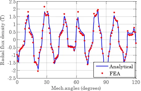
Fig.2 and Fig.3 show the radial and tangential components of flux density in the middle of the airgap (r = 204.5mm) and the slot (r = 178.5mm) respectively. The results obtained have a good agreement with the FE ones.
0 30 60 90 120
-2.5 -2 -1.5 -1 -0.5 0 0.5 1 1.5 2 2.5
Mech.angles (degrees)
R
ad
ia
l f
lu
x
den
si
ty
(T
)
Analytical FEA
0 30 60 90 120 -1.5
-1.2 -0.9 -0.6 -0.3 0 0.3 0.6 0.9 1.2 1.5
Mech.angles (degrees)
R
ad
ia
l f
lu
x
den
si
ty
(T
)
Analytical FEA
(b)
Fig.2. (a) Radial (b) tangential flux density in the middle of the airgap (r = 204.5 mm)
0 1.18 2.36 3.54 4.72 5.9
0 0.01 0.02 0.03 0.04 0.05
Angle (mech.degrees)
R
ad
ia
l f
lu
x
den
si
ty
(T
)
Analytical FE
(a)
0 1.18 2.36 3.54 4.72 5.9
0.338 0.34 0.342 0.344 0.346 0.348
Angle (mech.degrees)
T
an
gen
ti
al
fl
u
x
den
si
ty
(T
) Analytical
FE
(b)
Fig.3. (a) Radial (b) tangential flux density in the middle of the slot-domain (r = 178.5mm)
Fig.4 shows the comparison between the analytically and the FE calculated winding losses in a coil under
no-load (J = 0; Br = 1.02T)and also on peak load (J = 16.05 A/mm2; Br = 1.02T) conditions, respectively. The
obtained results are shown in Fig.4 to be in a good agreement. For a given operating speed, the computation time
for loss estimation is about 1.7 s with the analytical model whereas the FE takes about 6.2 minutes.
From Fig.4b, it can also be seen that there is a difference (4% - 11%) at frequencies over ~80Hz (apparition of skin effect). Using equation (3.1), it can be shown how, for example, for a fundamental operating frequency
of 63Hz the maximal skin depth is 8.33 mm; In this case, the conductor has an area of 7.84 mm2 (5.6 mm
0 10 20 30 40 50 60 70 80 90 100 0
10 20 30 40 50 60 70 80 90
Frequency (Hz)
W
in
di
n
g
los
ses
(W
)
Analytical FEA
(a)
0 10 20 30 40 50 60 70 80 90 100
500 600 700 800 900 1000 1100
Frequency (Hz)
W
in
di
n
g
los
ses
(W
)
Analytical FEA
(b)
Fig.4. Winding losses in a coil at (a) no-load (Jc = 0; Br = 1.02T) and (b) load (Jc = 16.05 A/mm2; Br = 1.02T) conditions.
From Fig.4 it also can be seen that the analytically calculated results are slightly higher than the FE calculated ones at frequencies higher than 80Hz although eddy current reaction effect is considered in FE computation. This is due to the role of eddy current and their reaction effect that change the current distribution within the conductor resulting in a decrease of eddy current losses [3]. It is worth noting that this reaction effect depends on the size and structure of the conductor [2].
From the results it also can be seen that the winding AC losses which include both DC losses and eddy current losses, are 35% higher than DC losses at nominal speed of 180 rpm (63Hz). As a result the overall efficiency drops by 4.9% if the eddy current losses are not considered in the design stage.
A method by which to diminish these eddy current losses is the implementation of Litz or multi-strand bundle conductors. However this comes at the cost of a further increase in DC losses, automatically reducing the overall efficiency. A comparative exercise in order to define the optimal balance between the AC losses and DC losses is thus done and this is presented in the following section.
5. Proximity losses investigation in multi-stranded bundle conductors
In this section, the proximity losses and their influence on machine’s efficiency are investigated for various multi-stranded bundle conductors with different cross-sectional areas and number of turns. For clarity of reading, parallel conductors and conductor that includes a number of parallel conductors are referred to as sub-stand and bundle conductor (see Fig.5) throughout this section. The losses are investigated for nine cases in which the turns’ number of bundle conductors is kept constant (33 turns per coil), but the number of sub-strands associated to a bundle are varied from one to nine to identify the changes in the current distribution and their influences on the total winding losses. A sub-strand for a
bundle is the original design and others are considered alternative.
current. In the losses computation, the current flow in each sub-strand is therefore accounted for individually in the post processing stage by introducing the total current flow in the sub-strands as functions of inductance variation.
For the losses computation, the fill factor for each configuration of bundle conductor is evaluated
assuming the slot is filled with a fill factor Kf (See Table 2). In the fill factor evaluation, insulation thickness
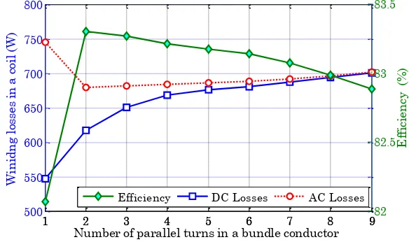
of each strand in the bundle conductor and the slot wall insulation are assumed to be identical. For each configuration both DC losses and AC losses are calculated at rated operation. The obtained results are given in Fig.6.
Sub- strand Insulation
[image:7.595.195.410.178.306.2]Bundle conductor
Fig. 5. An illustration of the bundle conductors and its sub-strands within a slot (8 sub-strands per bundle here)
TABLE 2
FILL FACTOR EVALUATION FOR DIFFERENT BUNDLE ARRANGEMENTS
Description Fill factor (Kf)
33 bundle conductors and 1 sub-strand per bundle 0.61 33 bundle conductors and 2 sub-strand per bundle 0.52 33 bundle conductors and 4 sub-strand per bundle 0.46 33 bundle conductors and 8 sub-strand per bundle 0.41
It can be clearly seen that as expected the DC losses increase as the sub-strands in a bundle conductor increases. The AC losses initially reduce and then increase as the sub-strands in the bundle conductor increases. This is mainly due to the reduction in eddy current losses whilst the DC losses increase with the winding fill factor decreasing. Also it is worth noting that the efficiency of the machine is influenced by the number of sub-strands. The efficiency is improved by 1.5% when employing two sub-strands within a bundle. This confirms that utilizing a sub-strand configuration influences the current distribution in the slot and thus, efficiency can be improved if sub-strands are properly adopted.
1 2 3 4 5 6 7 8 9
500 550 600 650 700 750 800
Number of parallel turns in a bundle conductor
W
in
id
n
g
los
ses
in
a
c
oi
l (
W
)
1 2 3 4 5 6 7 8 982
82.5 83 83.5
E
ff
ic
ien
cy
(
%
)
[image:7.595.154.446.509.682.2]Efficiency DC Losses AC Losses
Fig.6. AC and DC losses vs. number of conductors in bundle conductors
conductors and 2 sub-strands per bundle. The thermal analysis is carried out using 2D FE. The analysis is done at rated conditions where the previous analytically calculated AC losses are used. The temperature distributions in the slot for associated losses are presented in Fig.7.
175 oC
166 oC
(a) (b)
Fig.7. Temperature distribution of (a) 33 bundle conductors and 1 sub-strand and (b) 33 bundle conductors and 2 sub-strands
From the results, it is evident that the application of two parallel conductors per turn significantly reduces the losses without affecting the cooling arrangement of the design; also it reduces the slot temperature compared to the initial design of the machine. Hence, it can be concluded that the choice of the sub-strands number/cross-sectional area of a bundle conductor becomes an important factor which is necessary to consider during the design stage, in order to balance the AC losses and their DC counterpart. It is also worth highlighting here that the proximity losses can be reduced significantly due to current re-distribution of parallel conductors, although the transposition is not adopted.
5. Conclusion
In this paper, the influence of proximity losses in PM motor used for aircraft taxing has been investigated. A 36 slots and 42-poles an out-runner PM machine is used for the studies. An analytical model able to predict the machine performance in terms of these losses has been proposed. By comparing with FE results, the validity of the analytical model has been proven. It has been shown that the multi-stranded conductors have influences on proximity effect due to changes in current distribution in a slot and thus, the resultant proximity losses not only depend on twisting or transposing the windings, but also on number of sub-strands implemented within a bundle conductor arrangement. Furthermore, efficiency can be improved at the design stage by investigating and adopting an appropriate configuration in terms of the cross sectional area/ number of turns of multi-strand bundle conductors.
ACKNOWLEDGEMENT
This work was partly supported by the “EU FP7 funding via the CleanSky JTI – Systems for Green Operations ITD”.
References
[1] Y. Amara, P. Reghem, G. Barakat, Analytical prediction of eddy-current loss in armature windings of permanent magnet brushless ac machines, IEEE Transactions on Magnetics, vol. 46, pp. 3481-3484, 2010.
[2] P. Arumugam, T. Hamiti, C. Brunson, C. Gerada, Analysis of vertical strip wound fault-tolerant permanent magnet synchronous machines, IEEE Transactions on Industrial Electronics, vol. 61, pp. 1158-1168, 2014.
[3] P. Arumugam, T. Hamiti, C. Gerada, Estimation of eddy current loss in semi-closed slot vertical conductor permanent magnet synchronous machines considering eddy current reaction effect, IEEE Transactions on Magnetics, vol. 49, pp. 5326-5335, 2013.
[5] T. Lubin, S. Mezani, A. Rezzoug, 2-D Exact analytical model for surface-mounted permanent-magnet motors with semi-closed slots, IEEE Transactions on Magnetics, vol. 47, pp. 479-492, 2011.
[6] P.H. Mellor, R. Wrobel, N. McNeill, Investigation of proximity losses in a high speed brushless permanent magnet motor, IEEE Industry Applications Conference, vol.3, pp.1514,1518, 8-12 Oct. 2006.