Article
An Open-Source Toolbox for PEM Fuel
Cell Simulation
Jean-Paul Kone1,*ID, Xinyu Zhang1,2,*ID, Yuying Yan2,3and Stephen Adegbite2,4
1 International Doctoral Innovation Centre, University of Nottingham Ningbo China, 199 Taikang East Road,
Ningbo 315100, China
2 Research Centre for Fluids and Thermal Engineering, University of Nottingham Ningbo China,
199 Taikang East Road; Ningbo 315100, China; [email protected] (Y.Y.); [email protected] (S.A.)
3 Fluids & Thermal Engineering Research Group, University of Nottingham, University Park,
Nottingham NG7 2RD, UK
4 Department of Chemical and Environmental Engineering, University of Nottingham Ningbo China,
Ningbo 315100, China
* Correspondence: [email protected] (J.-P.K.); [email protected] (X.Z.); Tel.: +86-152-5838-3974 (J.-P.K.); Tel.: +86-180-5826-1662 (X.Z.)
Received: 30 March 2018; Accepted: 2 May 2018; Published: 10 May 2018
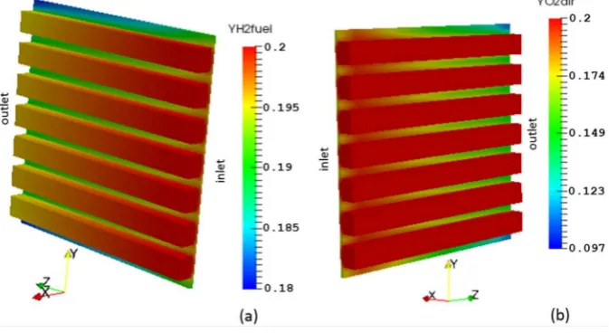
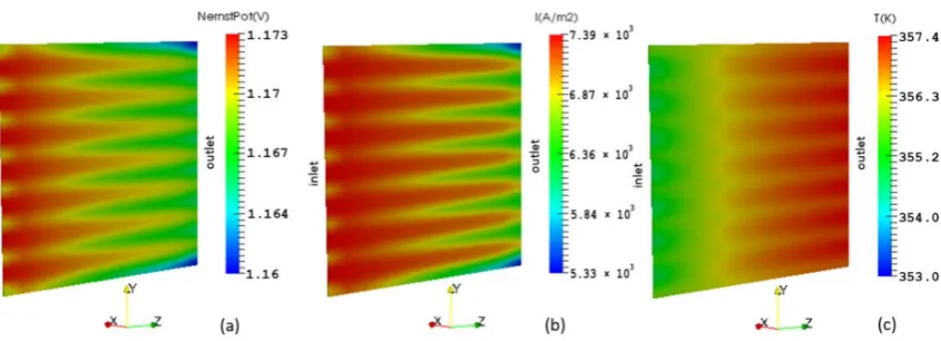
Abstract:In this paper, an open-source toolbox that can be used to accurately predict the distribution of the major physical quantities that are transported within a proton exchange membrane (PEM) fuel cell is presented. The toolbox has been developed using the Open Source Field Operation and Manipulation (OpenFOAM) platform, which is an open-source computational fluid dynamics (CFD) code. The base case results for the distribution of velocity, pressure, chemical species, Nernst potential, current density, and temperature are as expected. The plotted polarization curve was compared to the results from a numerical model and experimental data taken from the literature. The conducted simulations have generated a significant amount of data and information about the transport processes that are involved in the operation of a PEM fuel cell. The key role played by the concentration constant in shaping the cell polarization curve has been explored. The development of the present toolbox is in line with the objectives outlined in the International Energy Agency (IEA, Paris, France) Advanced Fuel Cell Annex 37 that is devoted to developing open-source computational tools to facilitate fuel cell technologies. The work therefore serves as a basis for devising additional features that are not always feasible with a commercial code.
Keywords:computational fluid dynamics; modelling; numerical; open-source code; proton exchange membrane fuel cell; simulation
1. Introduction
A proton exchange membrane (PEM) fuel cell is an electrochemical device used to convert the chemical energy of hydrogen into electrical energy, releasing heat in the process while producing water as the only by-product of the electrochemical reactions. It is thus a clean energy technology that has become an attractive option for replacing some of the carbon-based fuel energy systems since fossil fuel resources are increasingly scarce and they produce a significant amount of pollutants [1].
PEM fuel cells have many other advantages apart from being environmentally friendly energy conversion devices. They can directly convert the chemical energy of hydrogen into useful work without undergoing any thermodynamic cycle, resulting in higher efficiencies in direct electrical energy conversion. In addition, they have higher power densities and operate at lower temperatures,
making them a suitable choice for automotive power systems, as well as power generation devices for portable electronics and stationary units [1].
Nonetheless, the high manufacturing and performance test costs associated with PEM fuel cell systems constitute a major hurdle for their rapid development in terms of experimental studies. Therefore, many researches on PEM fuel cells have focused on improving the cell performance by maximizing its efficiency while minimizing manufacturing and test costs through CFD techniques [1–5]. Most of the current state of the art work is concerned with the effects of modelling parameters on cell polarization [6–17].
As for open-source modelling of PEM fuel cells using OpenFOAM, this paragraph is intended to examine most of the literature’s models, though it is likely that it may not include all the published models. Therefore, only the most pertinent issues that are relevant in the context of the present work are examined. Barreras et al. [18] and Lozano et al. [19] developed two dimensional (2-D) OpenFOAM CFD models for investigating the performance of bipolar plates in PEM fuel cells. Besides being 2-D, these models only consider a single fuel cell component (e.g., bipolar plate). It has been shown that transport in PEM fuel cells is three dimensional (3-D) in nature and requires the coupling of multiple regions in the fuel cell. Mustata et al. [20], Valino et al. [21] and Imbrioscia and Fasoli [22] subsequently presented 3-D OpenFOAM CFD models of bipolar plates. Although their models are 3-D, they are also limited to the bipolar plates, and they do not consider the coupling of transport phenomena in the multiple regions of the fuel cell. Valino et al. [23] introduced a 3-D OpenFOAM model for a complete cell. However, this model assumes an isothermal condition, meaning that the transport of thermal energy is not solved. This can produce results that are not physically representative. It has been shown that the impact of temperature distribution is very significant. In addition, the source codes of these models are not readily available to the public, and thus, like commercial software, they offer no flexibility.
In this work, a 3-D, non-isothermal and single-phase flow OpenFOAM model of a complete cell (including all fuel cell components) is developed. The Nernst equation is used for computing the open-circuit potential as opposed to solving the charge conservation equation for determining the open-circuit potential in the literature models. The work aims to fill the research knowledge gap in comprehensive open-source computational models for PEM fuel cells that are numerically tractable. The model developed partially adapts the open-source computational model of a solid oxide fuel cell (SOFC) presented by [24], to a PEM fuel cell. It varies from the model of [24] because: it is a different type of fuel cell (in a PEM fuel cell, hydrogen protons cross the membrane to the cathode, as opposed to oxygen ions crossing to the anode in SOFC); the geometry is different; the boundary conditions are different; and the electrochemistry is different. Furthermore, this model has been developed using OpenFOAM version 4.0, which has a superior design and far newer functionalities compared to version 2.1.x adopted in [24].
2. Mathematical Model
2.1. Cell Geometry and Transport Processes
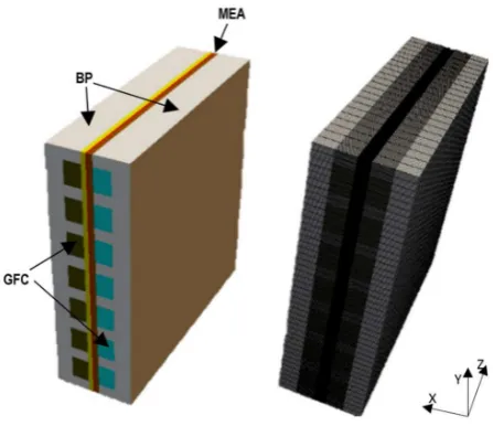
Figure 1.Geometry and mesh of a single cell proton exchange membrane (PEM) fuel cell.
Table 1.The cell geometric dimensions [25].
BP GFC GDL CL Membrane
x-width (mm) 3 1.5 0.41 0.0037 0.127
y-height (mm) 22 2 22 22 22
z-length (mm) 22 22 22 22 22
As illustrated in Figure2, the computational domain consists of both solid and fluid regions. The solid region is comprised of the membrane and the BPs, whereas the fluid region contains the GFCs, the GDLs, and the CLs. The reactant gases and the product water are transported within the fluid region. The porous electrodes carry the heat released by the electrochemical reactions to the cooling system through the BPs. Therefore, the field variables that need to be solved in these regions are different. The solid is governed by the conservation of energy, whereas the fluid is governed by the conservations of mass, momentum, chemical species, and energy.
[image:3.595.147.453.518.737.2]In the numerical model presented in this work, the conservation equations are coupled with the solution of the Nernst equation. In other words, the transport of mass, momentum, and chemical species are coupled with electrochemical reactions to create a more tractable numerical model. The energy equation solved in the solid region is coupled with the energy solutions in the fluid region.
2.2. Assumptions
Steady-state operating condition is assumed, with the gas flow considered to be laminar and incompressible due to low velocities. The individual gases and the gas mixture are considered as ideal gases. The fuel cell components are assumed to be isotropic and homogeneous. The membrane is assumed to be fully humidified and impermeable to reactant gases [26]. The electrochemical reactions are assumed to occur at the cathode electrode-membrane interface [24]. The anode’s activation and mass transport overpotentials are taken as negligible [26]. Ohmic heating in the bipolar plates is neglected due to high heat conductivity and the electrical potential distribution is taken as constant within the bipolar plates due to high electrical conductivity of the bipolar plate material [27,28]. The outer walls of the entire cell are taken as impassable to heat [24].
2.3. Governing Equations Mass conservation:
Computation 2018, 6, x FOR PEER REVIEW 4 of 17
In the numerical model presented in this work, the conservation equations are coupled with the solution of the Nernst equation. In other words, the transport of mass, momentum, and chemical species are coupled with electrochemical reactions to create a more tractable numerical model. The energy equation solved in the solid region is coupled with the energy solutions in the fluid region.
2.2. Assumptions
Steady-state operating condition is assumed, with the gas flow considered to be laminar and incompressible due to low velocities. The individual gases and the gas mixture are considered as ideal gases. The fuel cell components are assumed to be isotropic and homogeneous. The membrane is assumed to be fully humidified and impermeable to reactant gases [26]. The electrochemical reactions are assumed to occur at the cathode electrode-membrane interface [24]. The anode’s activation and mass transport overpotentials are taken as negligible [26]. Ohmic heating in the bipolar plates is neglected due to high heat conductivity and the electrical potential distribution is taken as constant within the bipolar plates due to high electrical conductivity of the bipolar plate material [27,28]. The outer walls of the entire cell are taken as impassable to heat [24].
2.3. Governing Equations
Mass conservation:
∙ ⃗ = 0 (1)
Momentum conservation:
∙ ⃗ ⃗ = − + ∙ ⃗ + (2)
where the momentum source term SM, is equal to zero in the gas flow channels and to the Darcy resistance in the porous media, given by:
= − ⃗ (3)
Chemical species conservation:
∙ ⃗ = ( ∙ ) (4)
where the mass fraction of the inert species is calculated using the sum of the other species (1 −
∑ ).
Energy conservation:
∙ ( ⃗ ) = ∙ ( ) + (5)
where the energy source term SE, is essentially due to the heat released by the electrochemical reaction determined by:
= − ∆ (6)
The cell voltage:
= − − − (7)
Additional constitutive relations for linking the various physical quantities are given in Table 2.
Table 2. Constitutive equations.
Description Symbol Expression Source
Gas density ρ ∑ ⁄ -
Mole fraction xi ∑ ⁄ -
Specific heat capacity cp ∑ ∗ -
·(ρ →
U) =0 (1)
Momentum conservation:
Computation 2018, 6, x FOR PEER REVIEW 4 of 17
In the numerical model presented in this work, the conservation equations are coupled with the solution of the Nernst equation. In other words, the transport of mass, momentum, and chemical species are coupled with electrochemical reactions to create a more tractable numerical model. The energy equation solved in the solid region is coupled with the energy solutions in the fluid region.
2.2. Assumptions
Steady-state operating condition is assumed, with the gas flow considered to be laminar and incompressible due to low velocities. The individual gases and the gas mixture are considered as ideal gases. The fuel cell components are assumed to be isotropic and homogeneous. The membrane is assumed to be fully humidified and impermeable to reactant gases [26]. The electrochemical reactions are assumed to occur at the cathode electrode-membrane interface [24]. The anode’s activation and mass transport overpotentials are taken as negligible [26]. Ohmic heating in the bipolar plates is neglected due to high heat conductivity and the electrical potential distribution is taken as constant within the bipolar plates due to high electrical conductivity of the bipolar plate material [27,28]. The outer walls of the entire cell are taken as impassable to heat [24].
2.3. Governing Equations
Mass conservation:
∙ ⃗ = 0 (1)
Momentum conservation:
∙ ⃗ ⃗ = − + ∙ ⃗ + (2)
where the momentum source term SM, is equal to zero in the gas flow channels and to the Darcy resistance in the porous media, given by:
= − ⃗ (3)
Chemical species conservation:
∙ ⃗ = ( ∙ ) (4)
where the mass fraction of the inert species is calculated using the sum of the other species (1 −
∑ ).
Energy conservation:
∙ ( ⃗ ) = ∙ ( ) + (5)
where the energy source term SE, is essentially due to the heat released by the electrochemical reaction determined by:
= − ∆ (6)
The cell voltage:
= − − − (7)
Additional constitutive relations for linking the various physical quantities are given in Table 2.
Table 2. Constitutive equations.
Description Symbol Expression Source
Gas density ρ ∑ ⁄ -
Mole fraction xi ∑ ⁄ -
Specific heat capacity cp ∑ ∗ -
·(ρ →
U→U) =−
Computation 2018, 6, x FOR PEER REVIEW 4 of 17
In the numerical model presented in this work, the conservation equations are coupled with the solution of the Nernst equation. In other words, the transport of mass, momentum, and chemical species are coupled with electrochemical reactions to create a more tractable numerical model. The energy equation solved in the solid region is coupled with the energy solutions in the fluid region.
2.2. Assumptions
Steady-state operating condition is assumed, with the gas flow considered to be laminar and incompressible due to low velocities. The individual gases and the gas mixture are considered as ideal gases. The fuel cell components are assumed to be isotropic and homogeneous. The membrane is assumed to be fully humidified and impermeable to reactant gases [26]. The electrochemical reactions are assumed to occur at the cathode electrode-membrane interface [24]. The anode’s activation and mass transport overpotentials are taken as negligible [26]. Ohmic heating in the bipolar plates is neglected due to high heat conductivity and the electrical potential distribution is taken as constant within the bipolar plates due to high electrical conductivity of the bipolar plate material [27,28]. The outer walls of the entire cell are taken as impassable to heat [24].
2.3. Governing Equations
Mass conservation:
∙ ⃗ = 0 (1)
Momentum conservation:
∙ ⃗ ⃗ = − + ∙ ⃗ + (2)
where the momentum source term SM, is equal to zero in the gas flow channels and to the Darcy resistance in the porous media, given by:
= − ⃗ (3)
Chemical species conservation:
∙ ⃗ = ( ∙ ) (4)
where the mass fraction of the inert species is calculated using the sum of the other species (1 −
∑ ).
Energy conservation:
∙ ( ⃗ ) = ∙ ( ) + (5)
where the energy source term SE, is essentially due to the heat released by the electrochemical reaction determined by:
= − ∆ (6)
The cell voltage:
= − − − (7)
Additional constitutive relations for linking the various physical quantities are given in Table 2.
Table 2. Constitutive equations.
Description Symbol Expression Source
Gas density ρ ∑ ⁄ -
Mole fraction xi ∑ ⁄ -
Specific heat capacity cp ∑ ∗ -
p+
Computation 2018, 6, x FOR PEER REVIEW 4 of 17
In the numerical model presented in this work, the conservation equations are coupled with the solution of the Nernst equation. In other words, the transport of mass, momentum, and chemical species are coupled with electrochemical reactions to create a more tractable numerical model. The energy equation solved in the solid region is coupled with the energy solutions in the fluid region.
2.2. Assumptions
Steady-state operating condition is assumed, with the gas flow considered to be laminar and incompressible due to low velocities. The individual gases and the gas mixture are considered as ideal gases. The fuel cell components are assumed to be isotropic and homogeneous. The membrane is assumed to be fully humidified and impermeable to reactant gases [26]. The electrochemical reactions are assumed to occur at the cathode electrode-membrane interface [24]. The anode’s activation and mass transport overpotentials are taken as negligible [26]. Ohmic heating in the bipolar plates is neglected due to high heat conductivity and the electrical potential distribution is taken as constant within the bipolar plates due to high electrical conductivity of the bipolar plate material [27,28]. The outer walls of the entire cell are taken as impassable to heat [24].
2.3. Governing Equations
Mass conservation:
∙ ⃗ = 0 (1)
Momentum conservation:
∙ ⃗ ⃗ = − + ∙ ⃗ + (2)
where the momentum source term SM, is equal to zero in the gas flow channels and to the Darcy resistance in the porous media, given by:
= − ⃗ (3)
Chemical species conservation:
∙ ⃗ = ( ∙ ) (4)
where the mass fraction of the inert species is calculated using the sum of the other species (1 −
∑ ).
Energy conservation:
∙ ( ⃗ ) = ∙ ( ) + (5)
where the energy source term SE, is essentially due to the heat released by the electrochemical reaction determined by:
= − ∆ (6)
The cell voltage:
= − − − (7)
Additional constitutive relations for linking the various physical quantities are given in Table 2.
Table 2. Constitutive equations.
Description Symbol Expression Source
Gas density ρ ∑ ⁄ -
Mole fraction xi ∑ ⁄ -
Specific heat capacity cp ∑ ∗ -
·(µ
Computation 2018, 6, x FOR PEER REVIEW 4 of 17
In the numerical model presented in this work, the conservation equations are coupled with the solution of the Nernst equation. In other words, the transport of mass, momentum, and chemical species are coupled with electrochemical reactions to create a more tractable numerical model. The energy equation solved in the solid region is coupled with the energy solutions in the fluid region.
2.2. Assumptions
Steady-state operating condition is assumed, with the gas flow considered to be laminar and incompressible due to low velocities. The individual gases and the gas mixture are considered as ideal gases. The fuel cell components are assumed to be isotropic and homogeneous. The membrane is assumed to be fully humidified and impermeable to reactant gases [26]. The electrochemical reactions are assumed to occur at the cathode electrode-membrane interface [24]. The anode’s activation and mass transport overpotentials are taken as negligible [26]. Ohmic heating in the bipolar plates is neglected due to high heat conductivity and the electrical potential distribution is taken as constant within the bipolar plates due to high electrical conductivity of the bipolar plate material [27,28]. The outer walls of the entire cell are taken as impassable to heat [24].
2.3. Governing Equations
Mass conservation:
∙ ⃗ = 0 (1)
Momentum conservation:
∙ ⃗ ⃗ = − + ∙ ⃗ + (2)
where the momentum source term SM, is equal to zero in the gas flow channels and to the Darcy resistance in the porous media, given by:
= − ⃗ (3)
Chemical species conservation:
∙ ⃗ = ( ∙ ) (4)
where the mass fraction of the inert species is calculated using the sum of the other species (1 −
∑ ).
Energy conservation:
∙ ( ⃗ ) = ∙ ( ) + (5)
where the energy source term SE, is essentially due to the heat released by the electrochemical reaction determined by:
= − ∆ (6)
The cell voltage:
= − − − (7)
Additional constitutive relations for linking the various physical quantities are given in Table 2.
Table 2. Constitutive equations.
Description Symbol Expression Source
Gas density ρ ∑ ⁄ -
Mole fraction xi ∑ ⁄ -
Specific heat capacity cp ∑ ∗ -
→
U) +SM (2)
where the momentum source termSM, is equal to zero in the gas flow channels and to the Darcy resistance in the porous media, given by:
SM=−
µ →
U
K (3)
Chemical species conservation:
Computation 2018, 6, x FOR PEER REVIEW 4 of 17
In the numerical model presented in this work, the conservation equations are coupled with the solution of the Nernst equation. In other words, the transport of mass, momentum, and chemical species are coupled with electrochemical reactions to create a more tractable numerical model. The energy equation solved in the solid region is coupled with the energy solutions in the fluid region.
2.2. Assumptions
Steady-state operating condition is assumed, with the gas flow considered to be laminar and incompressible due to low velocities. The individual gases and the gas mixture are considered as ideal gases. The fuel cell components are assumed to be isotropic and homogeneous. The membrane is assumed to be fully humidified and impermeable to reactant gases [26]. The electrochemical reactions are assumed to occur at the cathode electrode-membrane interface [24]. The anode’s activation and mass transport overpotentials are taken as negligible [26]. Ohmic heating in the bipolar plates is neglected due to high heat conductivity and the electrical potential distribution is taken as constant within the bipolar plates due to high electrical conductivity of the bipolar plate material [27,28]. The outer walls of the entire cell are taken as impassable to heat [24].
2.3. Governing Equations
Mass conservation:
∙ ⃗ = 0 (1)
Momentum conservation:
∙ ⃗ ⃗ = − + ∙ ⃗ + (2)
where the momentum source term SM, is equal to zero in the gas flow channels and to the Darcy resistance in the porous media, given by:
= − ⃗ (3)
Chemical species conservation:
∙ ⃗ = ( ∙ ) (4)
where the mass fraction of the inert species is calculated using the sum of the other species (1 −
∑ ).
Energy conservation:
∙ ( ⃗ ) = ∙ ( ) + (5)
where the energy source term SE, is essentially due to the heat released by the electrochemical reaction determined by:
= − ∆ (6)
The cell voltage:
= − − − (7)
Additional constitutive relations for linking the various physical quantities are given in Table 2.
Table 2. Constitutive equations.
Description Symbol Expression Source
Gas density ρ ∑ ⁄ -
Mole fraction xi ∑ ⁄ -
Specific heat capacity cp ∑ ∗ -
·(ρ →
Uyi) = (
Computation 2018, 6, x FOR PEER REVIEW 4 of 17
In the numerical model presented in this work, the conservation equations are coupled with the solution of the Nernst equation. In other words, the transport of mass, momentum, and chemical species are coupled with electrochemical reactions to create a more tractable numerical model. The energy equation solved in the solid region is coupled with the energy solutions in the fluid region.
2.2. Assumptions
Steady-state operating condition is assumed, with the gas flow considered to be laminar and incompressible due to low velocities. The individual gases and the gas mixture are considered as ideal gases. The fuel cell components are assumed to be isotropic and homogeneous. The membrane is assumed to be fully humidified and impermeable to reactant gases [26]. The electrochemical reactions are assumed to occur at the cathode electrode-membrane interface [24]. The anode’s activation and mass transport overpotentials are taken as negligible [26]. Ohmic heating in the bipolar plates is neglected due to high heat conductivity and the electrical potential distribution is taken as constant within the bipolar plates due to high electrical conductivity of the bipolar plate material [27,28]. The outer walls of the entire cell are taken as impassable to heat [24].
2.3. Governing Equations
Mass conservation:
∙ ⃗ = 0 (1)
Momentum conservation:
∙ ⃗ ⃗ = − + ∙ ⃗ + (2)
where the momentum source term SM, is equal to zero in the gas flow channels and to the Darcy resistance in the porous media, given by:
= − ⃗ (3)
Chemical species conservation:
∙ ⃗ = ( ∙ ) (4)
where the mass fraction of the inert species is calculated using the sum of the other species (1 −
∑ ).
Energy conservation:
∙ ( ⃗ ) = ∙ ( ) + (5)
where the energy source term SE, is essentially due to the heat released by the electrochemical reaction determined by:
= − ∆ (6)
The cell voltage:
= − − − (7)
Additional constitutive relations for linking the various physical quantities are given in Table 2.
Table 2. Constitutive equations.
Description Symbol Expression Source
Gas density ρ ∑ ⁄ -
Mole fraction xi ∑ ⁄ -
Specific heat capacity cp ∑ ∗ -
·ρD
Computation 2018, 6, x FOR PEER REVIEW 4 of 17
In the numerical model presented in this work, the conservation equations are coupled with the solution of the Nernst equation. In other words, the transport of mass, momentum, and chemical species are coupled with electrochemical reactions to create a more tractable numerical model. The energy equation solved in the solid region is coupled with the energy solutions in the fluid region.
2.2. Assumptions
Steady-state operating condition is assumed, with the gas flow considered to be laminar and incompressible due to low velocities. The individual gases and the gas mixture are considered as ideal gases. The fuel cell components are assumed to be isotropic and homogeneous. The membrane is assumed to be fully humidified and impermeable to reactant gases [26]. The electrochemical reactions are assumed to occur at the cathode electrode-membrane interface [24]. The anode’s activation and mass transport overpotentials are taken as negligible [26]. Ohmic heating in the bipolar plates is neglected due to high heat conductivity and the electrical potential distribution is taken as constant within the bipolar plates due to high electrical conductivity of the bipolar plate material [27,28]. The outer walls of the entire cell are taken as impassable to heat [24].
2.3. Governing Equations
Mass conservation:
∙ ⃗ = 0 (1)
Momentum conservation:
∙ ⃗ ⃗ = − + ∙ ⃗ + (2)
where the momentum source term SM, is equal to zero in the gas flow channels and to the Darcy resistance in the porous media, given by:
= − ⃗ (3)
Chemical species conservation:
∙ ⃗ = ( ∙ ) (4)
where the mass fraction of the inert species is calculated using the sum of the other species (1 −
∑ ).
Energy conservation:
∙ ( ⃗ ) = ∙ ( ) + (5)
where the energy source term SE, is essentially due to the heat released by the electrochemical reaction determined by:
= − ∆ (6)
The cell voltage:
= − − − (7)
Additional constitutive relations for linking the various physical quantities are given in Table 2.
Table 2. Constitutive equations.
Description Symbol Expression Source
Gas density ρ ∑ ⁄ -
Mole fraction xi ∑ ⁄ -
Specific heat capacity cp ∑ ∗ -
yi) (4)
where the mass fraction of the inert species is calculated using the sum of the other species (1−∑ni=−11yi). Energy conservation:
Computation 2018, 6, x FOR PEER REVIEW 4 of 17
In the numerical model presented in this work, the conservation equations are coupled with the solution of the Nernst equation. In other words, the transport of mass, momentum, and chemical species are coupled with electrochemical reactions to create a more tractable numerical model. The energy equation solved in the solid region is coupled with the energy solutions in the fluid region.
2.2. Assumptions
Steady-state operating condition is assumed, with the gas flow considered to be laminar and incompressible due to low velocities. The individual gases and the gas mixture are considered as ideal gases. The fuel cell components are assumed to be isotropic and homogeneous. The membrane is assumed to be fully humidified and impermeable to reactant gases [26]. The electrochemical reactions are assumed to occur at the cathode electrode-membrane interface [24]. The anode’s activation and mass transport overpotentials are taken as negligible [26]. Ohmic heating in the bipolar plates is neglected due to high heat conductivity and the electrical potential distribution is taken as constant within the bipolar plates due to high electrical conductivity of the bipolar plate material [27,28]. The outer walls of the entire cell are taken as impassable to heat [24].
2.3. Governing Equations
Mass conservation:
∙ ⃗ = 0 (1)
Momentum conservation:
∙ ⃗ ⃗ = − + ∙ ⃗ + (2)
where the momentum source term SM, is equal to zero in the gas flow channels and to the Darcy resistance in the porous media, given by:
= − ⃗ (3)
Chemical species conservation:
∙ ⃗ = ( ∙ ) (4)
where the mass fraction of the inert species is calculated using the sum of the other species (1 −
∑ ).
Energy conservation:
∙ ( ⃗ ) = ∙ ( ) + (5)
where the energy source term SE, is essentially due to the heat released by the electrochemical reaction determined by:
= − ∆ (6)
The cell voltage:
= − − − (7)
Additional constitutive relations for linking the various physical quantities are given in Table 2.
Table 2. Constitutive equations.
Description Symbol Expression Source
Gas density ρ ∑ ⁄ -
Mole fraction xi ∑ ⁄ -
Specific heat capacity cp ∑ ∗ -
·(ρcp →
UT) =
Computation 2018, 6, x FOR PEER REVIEW 4 of 17
In the numerical model presented in this work, the conservation equations are coupled with the solution of the Nernst equation. In other words, the transport of mass, momentum, and chemical species are coupled with electrochemical reactions to create a more tractable numerical model. The energy equation solved in the solid region is coupled with the energy solutions in the fluid region.
2.2. Assumptions
Steady-state operating condition is assumed, with the gas flow considered to be laminar and incompressible due to low velocities. The individual gases and the gas mixture are considered as ideal gases. The fuel cell components are assumed to be isotropic and homogeneous. The membrane is assumed to be fully humidified and impermeable to reactant gases [26]. The electrochemical reactions are assumed to occur at the cathode electrode-membrane interface [24]. The anode’s activation and mass transport overpotentials are taken as negligible [26]. Ohmic heating in the bipolar plates is neglected due to high heat conductivity and the electrical potential distribution is taken as constant within the bipolar plates due to high electrical conductivity of the bipolar plate material [27,28]. The outer walls of the entire cell are taken as impassable to heat [24].
2.3. Governing Equations
Mass conservation:
∙ ⃗ = 0 (1)
Momentum conservation:
∙ ⃗ ⃗ = − + ∙ ⃗ + (2)
where the momentum source term SM, is equal to zero in the gas flow channels and to the Darcy resistance in the porous media, given by:
= − ⃗ (3)
Chemical species conservation:
∙ ⃗ = ( ∙ ) (4)
where the mass fraction of the inert species is calculated using the sum of the other species (1 −
∑ ).
Energy conservation:
∙ ( ⃗ ) = ∙ ( ) + (5)
where the energy source term SE, is essentially due to the heat released by the electrochemical reaction determined by:
= − ∆ (6)
The cell voltage:
= − − − (7)
Additional constitutive relations for linking the various physical quantities are given in Table 2.
Table 2. Constitutive equations.
Description Symbol Expression Source
Gas density ρ ∑ ⁄ -
Mole fraction xi ∑ ⁄ -
Specific heat capacity cp ∑ ∗ -
·(k
Computation 2018, 6, x FOR PEER REVIEW 4 of 17
In the numerical model presented in this work, the conservation equations are coupled with the solution of the Nernst equation. In other words, the transport of mass, momentum, and chemical species are coupled with electrochemical reactions to create a more tractable numerical model. The energy equation solved in the solid region is coupled with the energy solutions in the fluid region.
2.2. Assumptions
Steady-state operating condition is assumed, with the gas flow considered to be laminar and incompressible due to low velocities. The individual gases and the gas mixture are considered as ideal gases. The fuel cell components are assumed to be isotropic and homogeneous. The membrane is assumed to be fully humidified and impermeable to reactant gases [26]. The electrochemical reactions are assumed to occur at the cathode electrode-membrane interface [24]. The anode’s activation and mass transport overpotentials are taken as negligible [26]. Ohmic heating in the bipolar plates is neglected due to high heat conductivity and the electrical potential distribution is taken as constant within the bipolar plates due to high electrical conductivity of the bipolar plate material [27,28]. The outer walls of the entire cell are taken as impassable to heat [24].
2.3. Governing Equations
Mass conservation:
∙ ⃗ = 0 (1)
Momentum conservation:
∙ ⃗ ⃗ = − + ∙ ⃗ + (2)
where the momentum source term SM, is equal to zero in the gas flow channels and to the Darcy resistance in the porous media, given by:
= − ⃗ (3)
Chemical species conservation:
∙ ⃗ = ( ∙ ) (4)
where the mass fraction of the inert species is calculated using the sum of the other species (1 −
∑ ).
Energy conservation:
∙ ( ⃗ ) = ∙ ( ) + (5)
where the energy source term SE, is essentially due to the heat released by the electrochemical reaction determined by:
= − ∆ (6)
The cell voltage:
= − − − (7)
Additional constitutive relations for linking the various physical quantities are given in Table 2.
Table 2. Constitutive equations.
Description Symbol Expression Source
Gas density ρ ∑ ⁄ -
Mole fraction xi ∑ ⁄ -
Specific heat capacity cp ∑ ∗ -
T) +SE (5)
where the energy source termSE, is essentially due to the heat released by the electrochemical reaction determined by:
SE= I
δMEA
(η−T∆S
niF
) (6)
The cell voltage:
Vcell=ENernst−ηact−ηohm−ηcon (7)
Table 2.Constitutive equations.
Description Symbol Expression Source
Gas density ρ RT∑pyi/Mi
-Mole fraction xi
yi
Mi∑yj/Mj
-Specific heat capacity cp
cp mol 10−3∑y
i∗Mi
-Thermal conductivity k
n
∑
i=1 xiki
∑n
j=1xiAij [29]
Diffusivity of gas species i Di-mix
1−xi
∑j6=iDjixj [30]
Effective global diffusivity De f fi De f fi−1mix
+ 1
De f fi−Knud [31]
Effective species diffusivity De f fi−mix
ε
τDi−mix [31]
Effective Knudsen diffusivity De f fi−Knud
ε
τDi−Knud [31]
Knudsen diffusion coefficient Di-Knud 97×d2p(MT
i) 1/2
[32]
Nernst potential ENernst E0+RTzFlnQ
-Area specific resistance RΩ R0δMEMσi[dxλ(x)]+
2δ
σe+RBP+RC [33]
Membrane ionic conductivity σi (0.5139λ−0.326)exp(1268×(3031 −T1)) [33] Membrane water content λ
0.043+17.18a−39.85a2+36a3 (0<a<1)
14+1.4(a−1) (1≤a≤3) [33]
Water vapor activity a xWV×p
psat [33]
Saturation pressure logpsat
−2.1794+0.02953(T−273.15)−9.1837×
10−5(T−273.15)2+1.4454×10⁻⁷(T−273.15)3 [33]
Activation overpotential ηact RTαFln(II0) [26]
Ohmic overpotential ηohm RΩI [26]
Concentration overpotential ηcon cln(ILI−LI) [34]
Concentration constant c RT
nF(1+1α) [34]
Limiting current density IL nFDCδ [26]
Cathode exchange current density I0,C I0re fexp
h−
Eact
R (1T−353.151 )
i
[35] Species mass flux m.00
i = ±
I Mi
niF [26]
2.4. Boundary Conditions
The boundary and initial values are given in Table3. The inlet values for velocity, temperature, and mass fractions are given at the fluid inlets. Air and fuel inlet velocities are calculated according to [36]
U|inlet =ξ I
nFAMEA 1 xi RT p 1 Ach (8)
The outlet pressure value is prescribed at the outlet of both the anode and the cathode gas flow channels. For all other variables, Neumann boundary conditions are applied at the fluid outlets. Impermeability conditions are specified for mass and species flow at the membrane-fluid interfaces. Impermeability, no-slip, and no-flux boundary conditions are applied at all the internal surfaces within the modelling domain. A temperature of zero-gradient is applied at all the external surfaces.
Table 3.Boundary and initial values.
Equations Anode Inlet Anode Outlet Cathode Inlet Cathode Outlet Walls
Momentum Ufuel= 1.1055 m s−1 pfuel= 101,325 Pa Uair= 3.082 m s−1 pair= 101,325 Pa U= 0
Species transport yH2=0.2
yH2O=0.8
Computation 2018, 6, x FOR PEER REVIEW 4 of 17
In the numerical model presented in this work, the conservation equations are coupled with the solution of the Nernst equation. In other words, the transport of mass, momentum, and chemical species are coupled with electrochemical reactions to create a more tractable numerical model. The energy equation solved in the solid region is coupled with the energy solutions in the fluid region.
2.2. Assumptions
Steady-state operating condition is assumed, with the gas flow considered to be laminar and incompressible due to low velocities. The individual gases and the gas mixture are considered as ideal gases. The fuel cell components are assumed to be isotropic and homogeneous. The membrane is assumed to be fully humidified and impermeable to reactant gases [26]. The electrochemical reactions are assumed to occur at the cathode electrode-membrane interface [24]. The anode’s activation and mass transport overpotentials are taken as negligible [26]. Ohmic heating in the bipolar plates is neglected due to high heat conductivity and the electrical potential distribution is taken as constant within the bipolar plates due to high electrical conductivity of the bipolar plate material [27,28]. The outer walls of the entire cell are taken as impassable to heat [24].
2.3. Governing Equations
Mass conservation:
∙ ⃗ = 0 (1)
Momentum conservation:
∙ ⃗ ⃗ = − + ∙ ⃗ + (2)
where the momentum source term SM, is equal to zero in the gas flow channels and to the Darcy
resistance in the porous media, given by:
= − ⃗ (3)
Chemical species conservation:
∙ ⃗ = ( ∙ ) (4)
where the mass fraction of the inert species is calculated using the sum of the other species (1 − ∑ ).
Energy conservation:
∙ ( ⃗ ) = ∙ ( ) + (5)
where the energy source term SE, is essentially due to the heat released by the electrochemical reaction
determined by:
= − ∆ (6)
The cell voltage:
= − − − (7)
Additional constitutive relations for linking the various physical quantities are given in Table 2.
Table 2. Constitutive equations.
Description Symbol Expression Source
Gas density ρ ∑ ⁄ -
Mole fraction xi ∑ ⁄ -
Specific heat capacity cp ∑ ∗ -
yH2=0
Computation 2018, 6, x FOR PEER REVIEW 4 of 17
In the numerical model presented in this work, the conservation equations are coupled with the solution of the Nernst equation. In other words, the transport of mass, momentum, and chemical species are coupled with electrochemical reactions to create a more tractable numerical model. The energy equation solved in the solid region is coupled with the energy solutions in the fluid region.
2.2. Assumptions
Steady-state operating condition is assumed, with the gas flow considered to be laminar and incompressible due to low velocities. The individual gases and the gas mixture are considered as ideal gases. The fuel cell components are assumed to be isotropic and homogeneous. The membrane is assumed to be fully humidified and impermeable to reactant gases [26]. The electrochemical reactions are assumed to occur at the cathode electrode-membrane interface [24]. The anode’s activation and mass transport overpotentials are taken as negligible [26]. Ohmic heating in the bipolar plates is neglected due to high heat conductivity and the electrical potential distribution is taken as constant within the bipolar plates due to high electrical conductivity of the bipolar plate material [27,28]. The outer walls of the entire cell are taken as impassable to heat [24].
2.3. Governing Equations
Mass conservation:
∙ ⃗ = 0 (1)
Momentum conservation:
∙ ⃗ ⃗ = − + ∙ ⃗ + (2)
where the momentum source term SM, is equal to zero in the gas flow channels and to the Darcy
resistance in the porous media, given by:
= − ⃗ (3)
Chemical species conservation:
∙ ⃗ = ( ∙ ) (4)
where the mass fraction of the inert species is calculated using the sum of the other species (1 − ∑ ).
Energy conservation:
∙ ( ⃗ ) = ∙ ( ) + (5)
where the energy source term SE, is essentially due to the heat released by the electrochemical reaction
determined by:
= − ∆ (6)
The cell voltage:
= − − − (7)
Additional constitutive relations for linking the various physical quantities are given in Table 2.
Table 2. Constitutive equations.
Description Symbol Expression Source
Gas density ρ ∑ ⁄ -
Mole fraction xi ∑ ⁄ -
Specific heat capacity cp ∑ ∗ -
yH2O=0
yO2=0.2
yH2O=0.15
yN2=0.65
Computation 2018, 6, x FOR PEER REVIEW 4 of 17
In the numerical model presented in this work, the conservation equations are coupled with the solution of the Nernst equation. In other words, the transport of mass, momentum, and chemical species are coupled with electrochemical reactions to create a more tractable numerical model. The energy equation solved in the solid region is coupled with the energy solutions in the fluid region.
2.2. Assumptions
Steady-state operating condition is assumed, with the gas flow considered to be laminar and incompressible due to low velocities. The individual gases and the gas mixture are considered as ideal gases. The fuel cell components are assumed to be isotropic and homogeneous. The membrane is assumed to be fully humidified and impermeable to reactant gases [26]. The electrochemical reactions are assumed to occur at the cathode electrode-membrane interface [24]. The anode’s activation and mass transport overpotentials are taken as negligible [26]. Ohmic heating in the bipolar plates is neglected due to high heat conductivity and the electrical potential distribution is taken as constant within the bipolar plates due to high electrical conductivity of the bipolar plate material [27,28]. The outer walls of the entire cell are taken as impassable to heat [24].
2.3. Governing Equations
Mass conservation:
∙ ⃗ = 0 (1)
Momentum conservation:
∙ ⃗ ⃗ = − + ∙ ⃗ + (2)
where the momentum source term SM, is equal to zero in the gas flow channels and to the Darcy
resistance in the porous media, given by:
= − ⃗ (3)
Chemical species conservation:
∙ ⃗ = ( ∙ ) (4)
where the mass fraction of the inert species is calculated using the sum of the other species (1 − ∑ ).
Energy conservation:
∙ ( ⃗ ) = ∙ ( ) + (5)
where the energy source term SE, is essentially due to the heat released by the electrochemical reaction
determined by:
= − ∆ (6)
The cell voltage:
= − − − (7)
Additional constitutive relations for linking the various physical quantities are given in Table 2.
Table 2. Constitutive equations.
Description Symbol Expression Source
Gas density ρ ∑ ⁄ -
Mole fraction xi ∑ ⁄ -
Specific heat capacity cp ∑ ∗ -
yO2=0
Computation 2018, 6, x FOR PEER REVIEW 4 of 17
In the numerical model presented in this work, the conservation equations are coupled with the solution of the Nernst equation. In other words, the transport of mass, momentum, and chemical species are coupled with electrochemical reactions to create a more tractable numerical model. The energy equation solved in the solid region is coupled with the energy solutions in the fluid region.
2.2. Assumptions
Steady-state operating condition is assumed, with the gas flow considered to be laminar and incompressible due to low velocities. The individual gases and the gas mixture are considered as ideal gases. The fuel cell components are assumed to be isotropic and homogeneous. The membrane is assumed to be fully humidified and impermeable to reactant gases [26]. The electrochemical reactions are assumed to occur at the cathode electrode-membrane interface [24]. The anode’s activation and mass transport overpotentials are taken as negligible [26]. Ohmic heating in the bipolar plates is neglected due to high heat conductivity and the electrical potential distribution is taken as constant within the bipolar plates due to high electrical conductivity of the bipolar plate material [27,28]. The outer walls of the entire cell are taken as impassable to heat [24].
2.3. Governing Equations
Mass conservation:
∙ ⃗ = 0 (1)
Momentum conservation:
∙ ⃗ ⃗ = − + ∙ ⃗ + (2)
where the momentum source term SM, is equal to zero in the gas flow channels and to the Darcy
resistance in the porous media, given by:
= − ⃗ (3)
Chemical species conservation:
∙ ⃗ = ( ∙ ) (4)
where the mass fraction of the inert species is calculated using the sum of the other species (1 − ∑ ).
Energy conservation:
∙ ( ⃗ ) = ∙ ( ) + (5)
where the energy source term SE, is essentially due to the heat released by the electrochemical reaction
determined by:
= − ∆ (6)
The cell voltage:
= − − − (7)
Additional constitutive relations for linking the various physical quantities are given in Table 2.
Table 2. Constitutive equations.
Description Symbol Expression Source
Gas density ρ ∑ ⁄ -
Mole fraction xi ∑ ⁄ -
Specific heat capacity cp ∑ ∗ -
yH2O=0
Computation 2018, 6, x FOR PEER REVIEW 4 of 17
In the numerical model presented in this work, the conservation equations are coupled with the solution of the Nernst equation. In other words, the transport of mass, momentum, and chemical species are coupled with electrochemical reactions to create a more tractable numerical model. The energy equation solved in the solid region is coupled with the energy solutions in the fluid region.
2.2. Assumptions
Steady-state operating condition is assumed, with the gas flow considered to be laminar and incompressible due to low velocities. The individual gases and the gas mixture are considered as ideal gases. The fuel cell components are assumed to be isotropic and homogeneous. The membrane is assumed to be fully humidified and impermeable to reactant gases [26]. The electrochemical reactions are assumed to occur at the cathode electrode-membrane interface [24]. The anode’s activation and mass transport overpotentials are taken as negligible [26]. Ohmic heating in the bipolar plates is neglected due to high heat conductivity and the electrical potential distribution is taken as constant within the bipolar plates due to high electrical conductivity of the bipolar plate material [27,28]. The outer walls of the entire cell are taken as impassable to heat [24].
2.3. Governing Equations
Mass conservation:
∙ ⃗ = 0 (1)
Momentum conservation:
∙ ⃗ ⃗ = − + ∙ ⃗ + (2)
where the momentum source term SM, is equal to zero in the gas flow channels and to the Darcy
resistance in the porous media, given by:
= − ⃗ (3)
Chemical species conservation:
∙ ⃗ = ( ∙ ) (4)
where the mass fraction of the inert species is calculated using the sum of the other species (1 − ∑ ).
Energy conservation:
∙ ( ⃗ ) = ∙ ( ) + (5)
where the energy source term SE, is essentially due to the heat released by the electrochemical reaction
determined by:
= − ∆ (6)
The cell voltage:
= − − − (7)
Additional constitutive relations for linking the various physical quantities are given in Table 2.
Table 2. Constitutive equations.
Description Symbol Expression Source
Gas density ρ ∑ ⁄ -
Mole fraction xi ∑ ⁄ -
Specific heat capacity cp ∑
∗ -
yN2=0.
Computation 2018, 6, x FOR PEER REVIEW 4 of 17
In the numerical model presented in this work, the conservation equations are coupled with the solution of the Nernst equation. In other words, the transport of mass, momentum, and chemical species are coupled with electrochemical reactions to create a more tractable numerical model. The energy equation solved in the solid region is coupled with the energy solutions in the fluid region.
2.2. Assumptions
Steady-state operating condition is assumed, with the gas flow considered to be laminar and incompressible due to low velocities. The individual gases and the gas mixture are considered as ideal gases. The fuel cell components are assumed to be isotropic and homogeneous. The membrane is assumed to be fully humidified and impermeable to reactant gases [26]. The electrochemical reactions are assumed to occur at the cathode electrode-membrane interface [24]. The anode’s activation and mass transport overpotentials are taken as negligible [26]. Ohmic heating in the bipolar plates is neglected due to high heat conductivity and the electrical potential distribution is taken as constant within the bipolar plates due to high electrical conductivity of the bipolar plate material [27,28]. The outer walls of the entire cell are taken as impassable to heat [24].
2.3. Governing Equations
Mass conservation:
∙ ⃗ = 0 (1)
Momentum conservation:
∙ ⃗ ⃗ = − + ∙ ⃗ + (2)
where the momentum source term SM, is equal to zero in the gas flow channels and to the Darcy
resistance in the porous media, given by:
= − ⃗ (3)
Chemical species conservation:
∙ ⃗ = ( ∙ ) (4)
where the mass fraction of the inert species is calculated using the sum of the other species (1 − ∑ ).
Energy conservation:
∙ ( ⃗ ) = ∙ ( ) + (5)
where the energy source term SE, is essentially due to the heat released by the electrochemical reaction
determined by:
= − ∆ (6)
The cell voltage:
= − − − (7)
Additional constitutive relations for linking the various physical quantities are given in Table 2.
Table 2. Constitutive equations.
Description Symbol Expression Source
Gas density ρ ∑ ⁄ -
Mole fraction xi ∑ ⁄ -
Specific heat capacity cp ∑ ∗ -
y=0
Energy T= 353 K
Computation 2018, 6, x FOR PEER REVIEW 4 of 17
In the numerical model presented in this work, the conservation equations are coupled with the solution of the Nernst equation. In other words, the transport of mass, momentum, and chemical species are coupled with electrochemical reactions to create a more tractable numerical model. The energy equation solved in the solid region is coupled with the energy solutions in the fluid region.
2.2. Assumptions
Steady-state operating condition is assumed, with the gas flow considered to be laminar and incompressible due to low velocities. The individual gases and the gas mixture are considered as ideal gases. The fuel cell components are assumed to be isotropic and homogeneous. The membrane is assumed to be fully humidified and impermeable to reactant gases [26]. The electrochemical reactions are assumed to occur at the cathode electrode-membrane interface [24]. The anode’s activation and mass transport overpotentials are taken as negligible [26]. Ohmic heating in the bipolar plates is neglected due to high heat conductivity and the electrical potential distribution is taken as constant within the bipolar plates due to high electrical conductivity of the bipolar plate material [27,28]. The outer walls of the entire cell are taken as impassable to heat [24].
2.3. Governing Equations
Mass conservation:
∙ ⃗ = 0 (1)
Momentum conservation:
∙ ⃗ ⃗ = − + ∙ ⃗ + (2)
where the momentum source term SM, is equal to zero in the gas flow channels and to the Darcy
resistance in the porous media, given by:
= − ⃗ (3)
Chemical species conservation:
∙ ⃗ = ( ∙ ) (4)
where the mass fraction of the inert species is calculated using the sum of the other species (1 − ∑ ).
Energy conservation:
∙ ( ⃗ ) = ∙ ( ) + (5)
where the energy source term SE, is essentially due to the heat released by the electrochemical reaction
determined by:
= − ∆ (6)
The cell voltage:
= − − − (7)
Additional constitutive relations for linking the various physical quantities are given in Table 2.
Table 2. Constitutive equations.
Description Symbol Expression Source
Gas density ρ ∑ ⁄ -
Mole fraction xi ∑ ⁄ -
Specific heat capacity cp ∑ ∗ -
T=0 T= 353 K
Computation 2018, 6, x FOR PEER REVIEW 4 of 17
In the numerical model presented in this work, the conservation equations are coupled with the solution of the Nernst equation. In other words, the transport of mass, momentum, and chemical species are coupled with electrochemical reactions to create a more tractable numerical model. The energy equation solved in the solid region is coupled with the energy solutions in the fluid region.
2.2. Assumptions
Steady-state operating condition is assumed, with the gas flow considered to be laminar and incompressible due to low velocities. The individual gases and the gas mixture are considered as ideal gases. The fuel cell components are assumed to be isotropic and homogeneous. The membrane is assumed to be fully humidified and impermeable to reactant gases [26]. The electrochemical reactions are assumed to occur at the cathode electrode-membrane interface [24]. The anode’s activation and mass transport overpotentials are taken as negligible [26]. Ohmic heating in the bipolar plates is neglected due to high heat conductivity and the electrical potential distribution is taken as constant within the bipolar plates due to high electrical conductivity of the bipolar plate material [27,28]. The outer walls of the entire cell are taken as impassable to heat [24].
2.3. Governing Equations
Mass conservation:
∙ ⃗ = 0 (1)
Momentum conservation:
∙ ⃗ ⃗ = − + ∙ ⃗ + (2)
where the momentum source term SM, is equal to zero in the gas flow channels and to the Darcy
resistance in the porous media, given by:
= − ⃗ (3)
Chemical species conservation:
∙ ⃗ = ( ∙ ) (4)
where the mass fraction of the inert species is calculated using the sum of the other species (1 − ∑ ).
Energy conservation:
∙ ( ⃗ ) = ∙ ( ) + (5)
where the energy source term SE, is essentially due to the heat released by the electrochemical reaction
determined by:
= − ∆ (6)
The cell voltage:
= − − − (7)
Additional constitutive relations for linking the various physical quantities are given in Table 2.
Table 2. Constitutive equations.
Description Symbol Expression Source
Gas density ρ ∑ ⁄ -
Mole fraction xi ∑ ⁄ -
Specific heat capacity cp ∑ ∗ -
T=0
Computation 2018, 6, x FOR PEER REVIEW 4 of 17
In the numerical model presented in this work, the conservation equations are coupled with the solution of the Nernst equation. In other words, the transport of mass, momentum, and chemical species are coupled with electrochemical reactions to create a more tractable numerical model. The energy equation solved in the solid region is coupled with the energy solutions in the fluid region.
2.2. Assumptions
Steady-state operating condition is assumed, with the gas flow considered to be laminar and incompressible due to low velocities. The individual gases and the gas mixture are considered as ideal gases. The fuel cell components are assumed to be isotropic and homogeneous. The membrane is assumed to be fully humidified and impermeable to reactant gases [26]. The electrochemical reactions are assumed to occur at the cathode electrode-membrane interface [24]. The anode’s activation and mass transport overpotentials are taken as negligible [26]. Ohmic heating in the bipolar plates is neglected due to high heat conductivity and the electrical potential distribution is taken as constant within the bipolar plates due to high electrical conductivity of the bipolar plate material [27,28]. The outer walls of the entire cell are taken as impassable to heat [24].
2.3. Governing Equations
Mass conservation:
∙ ⃗ = 0 (1)
Momentum conservation:
∙ ⃗ ⃗ = − + ∙ ⃗ + (2)
where the momentum source term SM, is equal to zero in the gas flow channels and to the Darcy
resistance in the porous media, given by:
= − ⃗ (3)
Chemical species conservation:
∙ ⃗ = ( ∙ ) (4)
where the mass fraction of the inert species is calculated using the sum of the other species (1 − ∑ ).
Energy conservation:
∙ ( ⃗ ) = ∙ ( ) + (5)
where the energy source term SE, is essentially due to the heat released by the electrochemical reaction
determined by:
= − ∆ (6)
The cell voltage:
= − − − (7)
Additional constitutive relations for linking the various physical quantities are given in Table 2.
Table 2. Constitutive equations.
Description Symbol Expression Source
Gas density ρ ∑ ⁄ -
Mole fraction xi ∑ ⁄ -
Specific heat capacity cp ∑ ∗ -
3. Numerical Implementation
3.1. Computational Procedure
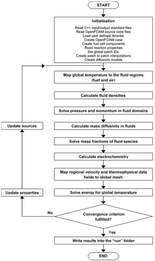
[image:6.595.144.453.210.729.2]The flow diagram of the solution procedure is shown in Figure3. The initialization phase is followed by an iteration loop where several calculations are repeated until convergence. For the potentiostatic (i.e., current density calculation) run, the cell voltage is fixed whereas for the galvanostatic (i.e., voltage calculation) run, it is adjusted until the computed mean current density is equal or very close to its initial value.
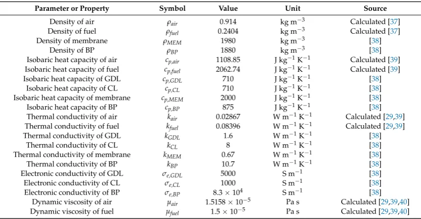
The physical constants and properties at cell operating temperature are given in Table 4. The electrochemical parameters and properties used are given in Table5. The case study operating conditions for the simulation campaign are summarized in Table6.
Table 4.Physical constants and properties at 353 K.
Parameter or Property Symbol Value Unit Source
Density of air ρair 0.914 kg m−3 Calculated [37]
Density of fuel ρfuel 0.2404 kg m−3 Calculated [37]
Density of membrane ρMEM 1980 kg m−3 [38]
Density of BP ρBP 1880 kg m−3 [38]
Isobaric heat capacity of air cp,air 1108.85 J kg−1K−1 Calculated [39]
Isobaric heat capacity of fuel cp,fuel 2062.74 J kg−1K−1 Calculated [39]
Isobaric heat capacity of GDL cp,GDL 710 J kg−1K−1 [38]
Isobaric heat capacity of CL cp,CL 710 J kg−1K−1 [38]
Isobaric heat capacity of membrane cp,MEM 2000 J kg−1K−1 [38]
Isobaric heat capacity of BP cp,BP 875 J kg−1K−1 [38]
Thermal conductivity of air kair 0.02867 W m−1K−1 Calculated [29,39] Thermal conductivity of fuel kfuel 0.08396 W m−1K−1 Calculated [29,39]
Thermal conductivity of GDL kGDL 1.6 W m−1K−1 [38]
Thermal conductivity of CL kCL 8 W m−1K−1 [38]
Thermal conductivity of membrane kMEM 0.67 W m−1K−1 [38]
Thermal conductivity of BP kBP 10.7 W m−1K−1 [38]
Electronic conductivity of GDL σe,GDL 5000 S m−1 [38]
Electronic conductivity of CL σe,CL 1000 S m−1 [38]
Electronic conductivity of BP σe,BP 8.3×10⁴ S m−1 [38]
Dynamic viscosity of air µair 1.5158×10⁻⁵ Pa s Calculated [29,39,40]
[image:7.595.94.505.422.526.2]Dynamic viscosity of fuel µfuel 1.5×10⁻⁵ Pa s Calculated [29,39,40]
Table 5.Electrochemical parameters and properties.
Parameter or Property Symbol Value Unit Source
Cathode charge transfer coefficient αc 1.0 - -Cathode activation energy Eact,c 73,220.0 J mol−1 [41] Reference exchange current density I0re f 0.0139 A m−2 [41] Enthalpy of formation of water vapor ∆HH2O −241.826×10³ J mol
−1 [42]
Standard entropy of hydrogen SH2 130.68 J mol
−1K−1 [42]
Standard entropy of oxygen SO2 205.152 J mol
−1K−1 [42]
Standard entropy of nitrogen SN2 191.609 J mol
−1K−1 [42]
Standard entropy of water vapor SH2O 188.835 J mol
−1K−1 [42]
Table 6.Case study operating conditions.
Variable Symbol Value Unit Source
Cell voltage V 0.6 V
-Cell temperature Tcell 353 K
-Air pressure pair 101,325 Pa
-Fuel pressure pfuel 101,325 Pa
-Air velocity Uair 3.082 m s−1 Calculated [36]
Fuel velocity Ufuel 1.1055 m s−1 Calculated [36]
Permeability of porous electrodes K 1.0×10⁻¹¹ m2
-O2fixed diffusivity in air mixture DO2,air 2.939×10
−5 m2s−1 Calculated [30,43,44]
Effective O2fixed diffusivity in air in GDL DOe f f
2,GDL 9.732×10
−6 m2s−1 Calculated [30–32,43,44]
Effective O2fixed diffusivity in air in CL De f fO
2,CL 7.785×10
−6 m2s−1 Calculated [30–32,43,44]
H2fixed diffusivity in fuel mixture DH2,f uel 0.122×10
−3 m2s−1 Calculated [30,43,44]
Effective H2fixed diffusivity in fuel in GDL De f fH2,GDL 4.031×10
−5 m2s−1 Calculated [30–32,43,44]
Effective H2fixed diffusivity in fuel in CL De f fH2,CL 1.252×10
−5 m2s−1 Calculated [30–32,43,44]
Mass fraction of O2 yO2 0.2 -
-Mass fraction of air H2O yH2O 0.15 -
-Mass fraction of N2 yN2 0.65 -
-Mass fraction of H2 yH2 0.2 -
[image:7.595.91.504.562.751.2]-3.2. Toolbox Structure
The present toolbox follows the same structure and organization as OpenFOAM, as depicted in Figure4. OpenFOAM is essentially a C++ library with its components falling into two main categories: solvers and utilities. Users can customize any existing components to suit their needs although this requires a good understanding of the software structure, as well as the programming techniques involved. One shortcoming of the OpenFOAM software package is that it has no PEM fuel cell module. Thus, the toolbox developed here provides remediation for this situation. It has two major components: pemfcSinglephaseNonIsothermalSolverandrun.
Figure 4.File structure of the toolbox.
3.2.1. PemfcSinglephaseNonIsothermalSolver
The pemfcSinglephaseNonIsothermalSolver folder contains the source code for the solver and libraries. A pemfcSinglephaseNonIsothermalSolver.c file that contains the main loop of the program is stored in the applications sub-folder. The lib sub-folder is where all necessary libraries are stored and compiled. These include, amongst other things, classes for multicomponent gas diffusivities, geometry, and mesh manipulation. The src sub-folder stores various program files containing specific instructions for the initialization phase and algorithms for solving field variables in the main loop. The individual solvers and other algorithmic controls and tolerances for these field variables are defined in the fvSolution files present in the system sub-folder of the run folder.
3.2.2. Run
The 0 sub-folder is a time sub-folder that stores the initial field data. In OpenFOAM, the time sub-folders store all the field data at various times; the name of each sub-folder corresponds to the time at which the simulation data were written. The data for the geometry construction and mesh creation are stored in the config sub-folder. The constant sub-folder contains a sub-sub-folder called polyMesh in which the mesh information and boundary condition files are stored, along with the physical property file. The files for the solution control, scheme and solvers are stored in the system sub-folder.
4. Model Verification
4.1. Mesh Independence Study
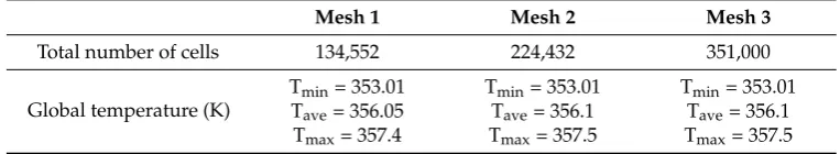
[image:9.595.106.488.338.408.2]To prove that the solution is independent from the mesh, a mesh independence study was conducted. This required refining the case study mesh twice by adding an extra 20% and 40% of the cells in every direction. Simulations at the case study conditions were then run with these refined meshes in order to compare the solutions for the temperature field. The numerical results, shown in Table7, showed that the maximum change of temperature solution is 0.03% for the compared meshes. This is evidence of the independence of the solution from the grid.
Table 7.Mesh independence.
Mesh 1 Mesh 2 Mesh 3
Total number of cells 134,552 224,432 351,000
Global temperature (K)
Tmin= 353.01 Tmin= 353.01 Tmin= 353.01
Tave= 356.05 Tave= 356.1 Tave= 356.1
Tmax= 357.4 Tmax= 357.5 Tmax= 357.5
4.2. Comparison with Literature Model Results and Experimental Data
![Table 8. Comparison of geometry and properties of present model with Yuan et al. [38] work.](https://thumb-us.123doks.com/thumbv2/123dok_us/8558199.364867/10.595.76.517.106.640/table-comparison-geometry-properties-present-model-yuan-work.webp)