MODELING OF IPM SYNCHRONOUS GENERATOR BY USING FUZZY LOGIC CONTROLLER UNDER
*Uossif Mohamed Matoug
Department of Electrical Engineering,
ARTICLE INFO ABSTRACT
This paper proposes a direct control strategy for an interior permanent magnet synchronous generator based variable speed by using fuzzy logic. In this scheme, the requirement of the continuous rotor position is eliminated as all the calculations are done
possesses advantages such as lesser parameter dependence and reduced number of controllers compared with the traditional indirect vector control scheme. Fuzzy logic adds to bivalent logic an important capability
information is information which in one or more respects is imprecise, uncertain, incomplete, unreliable, vague or partially true. In fuzzy logic, results of reasoning are expected to be
valid, or p
drawbacks of traditional indirect vector control scheme. The proposed control scheme is implemented in MATLAB/ Sim Power Systems and the results show
and varying wind speeds. Finally, a sensor less speed estimator is implemented, which enables the wind turbine to operate without the mechanical speed sensor.
Copyright©2017, Uossif Mohamed Matougand Dr. Pratibha Tiwari
which permits unrestricted use, distribution, and reproduction in any medium, provided the original work is properly cited.
INTRODUCTION
The wind energy will play a major role to meet the renewable energy target worldwide, to reduce the dependency on fossil fuel, and to minimize the impact of climate change. Renewable energy is generally defined as energy that comes from resources which are naturally replenished on a human timescale such as sunlight, wind, rain, tides, waves and geothermal heat. Renewable energy replaces conventional fuels in four distinct areas: electricity generation, hot water/space heating, motor fuels, and rural (off grid) energy services. Renewable energy resources exist over wide geographical areas, in contrast to other energy sources, which are concentrated in a limited number of countries. Rapid deployment of renewable energy and energy efficiency resulting in significant energy security, climate change mitigation, and economic benefits. In international public opinion surveys there is strong support for promoting renewable sources such as solar power and wind power. At the national level, at least 30 nations around the world already have renewable energy contributing more than 30 percent of
*Corresponding author: Uossif Mohamed Matoug,
Department of Electrical Engineering, Sam Higginbottom Institute of Agriculture and Technology Science, Allahabad, India
ISSN: 0975-833X
Article History:
Received 18th October, 2016
Received in revised form 17th November, 2016
Accepted 25th December, 2016
Published online 31st January,2017
Citation: Uossif Mohamed Matougand Dr. Pratibha Tiwari variable speed”, International Journal of Current Research
Key words:
Direct control,
Interior Permanent Magnet (IPM) Synchronous generator, Variable speed wind turbine, Fuzzy logic controller (FLC).
RESEARCH ARTICLE
MODELING OF IPM SYNCHRONOUS GENERATOR BY USING FUZZY LOGIC CONTROLLER UNDER
VARIABLE SPEED
Uossif Mohamed Matoug
and Dr. Pratibha Tiwari
Electrical Engineering, Sam Higginbottom Institute of Agriculture and
Allahabad (India)
ABSTRACT
This paper proposes a direct control strategy for an interior permanent magnet synchronous generator based variable speed by using fuzzy logic. In this scheme, the requirement of the continuous rotor position is eliminated as all the calculations are done in the stator reference frame. This scheme possesses advantages such as lesser parameter dependence and reduced number of controllers compared with the traditional indirect vector control scheme. Fuzzy logic adds to bivalent logic an important capability—a capability to reason precisely with imperfect information. Imperfect information is information which in one or more respects is imprecise, uncertain, incomplete, unreliable, vague or partially true. In fuzzy logic, results of reasoning are expected to be
valid, or p-valid for short. The direct control scheme is simpler and can eliminate some of the drawbacks of traditional indirect vector control scheme. The proposed control scheme is implemented in MATLAB/ Sim Power Systems and the results show that the controller can operate under constant and varying wind speeds. Finally, a sensor less speed estimator is implemented, which enables the wind turbine to operate without the mechanical speed sensor.
Pratibha Tiwari. This is an open access article distributed under the Creative Commons Att use, distribution, and reproduction in any medium, provided the original work is properly cited.
The wind energy will play a major role to meet the renewable energy target worldwide, to reduce the dependency on fossil fuel, and to minimize the impact of climate change. Renewable energy is generally defined as energy that comes from esources which are naturally replenished on a human timescale such as sunlight, wind, rain, tides, waves and geothermal heat. Renewable energy replaces conventional fuels in four distinct areas: electricity generation, hot and rural (off grid) energy Renewable energy resources exist over wide geographical areas, in contrast to other energy sources, which are concentrated in a limited number of countries. Rapid deployment of renewable energy and energy efficiency is resulting in significant energy security, climate change mitigation, and economic benefits. In international public opinion surveys there is strong support for promoting renewable sources such as solar power and wind power. At the nations around the world already have renewable energy contributing more than 30 percent of
Uossif Mohamed Matoug,
Department of Electrical Engineering, Sam Higginbottom Institute of India.
energy supply. National renewable energy markets are projected to continue to grow strongly in the coming decade and beyond currently, variable speed wind turbine technologies dominate the world market share due to their advantages over fixed speed generation such as increased energy capture, operation at maximum power point, improved efficiency, and power quality. Most of these wind turbines use doubly fed induction generator (DFIG) based variable speed wind turbines with gearbox This technology has an advantag
power electronic converter with reduced power rating (30%of full rated power) as the converter is connected to the rotor circuit. However, the use of gearbox in these turbines to couple the generator with the turbine causes problems. Moreover, gearbox requires regular maintenance as it suffers from faults and malfunctions. Variable speed wind turbine using permanent magnet synchronous generator (PMSG) without gearbox can enhance the performance of the wind energy conversion system. The use of permanent magnet in the rotor of the PMSG makes it unnecessary to supply magnetizing current through the stator for constant air
it can operate at higher power factor and efficiency. The previous works done on PMSG based wind turbine
based on surface permanent magnet
generator. Very few works have been done so far on interior PMSG-based wind turbines, which can produce additional power by exploiting their rotor saliency. It can also be operated
International Journal of Current Research
Vol. 9, Issue, 01, pp.45648-45654, January, 2017
INTERNATIONAL
OF CURRENT RESEARCH
and Dr. Pratibha Tiwari, 2017. “Modeling of IPM synchronous generator by using fuzzy logic controller under International Journal of Current Research, 9, (01), 45648-45654.
MODELING OF IPM SYNCHRONOUS GENERATOR BY USING FUZZY LOGIC CONTROLLER UNDER
Pratibha Tiwari
Sam Higginbottom Institute of Agriculture and Technology Science,
This paper proposes a direct control strategy for an interior permanent magnet synchronous generator-based variable speed by using fuzzy logic. In this scheme, the requirement of the continuous rotor
in the stator reference frame. This scheme possesses advantages such as lesser parameter dependence and reduced number of controllers compared with the traditional indirect vector control scheme. Fuzzy logic adds to bivalent logic an capability to reason precisely with imperfect information. Imperfect information is information which in one or more respects is imprecise, uncertain, incomplete, unreliable, vague or partially true. In fuzzy logic, results of reasoning are expected to be provably valid for short. The direct control scheme is simpler and can eliminate some of the drawbacks of traditional indirect vector control scheme. The proposed control scheme is implemented that the controller can operate under constant and varying wind speeds. Finally, a sensor less speed estimator is implemented, which enables the
is an open access article distributed under the Creative Commons Attribution License, use, distribution, and reproduction in any medium, provided the original work is properly cited.
supply. National renewable energy markets are projected to continue to grow strongly in the coming decade and beyond currently, variable speed wind turbine technologies dominate the world market share due to their advantages over ch as increased energy capture, operation at maximum power point, improved efficiency, and power quality. Most of these wind turbines use doubly fed induction generator (DFIG) based variable speed wind turbines with gearbox This technology has an advantage of having power electronic converter with reduced power rating (30%of full rated power) as the converter is connected to the rotor circuit. However, the use of gearbox in these turbines to couple the generator with the turbine causes problems. Moreover, the gearbox requires regular maintenance as it suffers from faults and malfunctions. Variable speed wind turbine using permanent magnet synchronous generator (PMSG) without gearbox can enhance the performance of the wind energy f permanent magnet in the rotor of the PMSG makes it unnecessary to supply magnetizing current through the stator for constant air-gap flux. Therefore, it can operate at higher power factor and efficiency. The previous works done on PMSG based wind turbines are mostly based on surface permanent magnet-type synchronous generator. Very few works have been done so far on interior based wind turbines, which can produce additional power by exploiting their rotor saliency. It can also be operated
INTERNATIONAL JOURNAL OF CURRENT RESEARCH
over a wide speed range (more than rated speed) by flux weakening, which will allow constant power-like operation at speeds higher than the rated speed. This work is based on interior permanent magnet-type synchronous generator-based variable speed wind turbine. There are different control strategies reported in the literature for permanent synchronous generator based variable speed wind turbine such as switch mode boost rectifier (uncontrolled diode rectifier cascaded by a boost dc–dc chopper), three-switch pulse width modulation (PWM) rectifier and six switch vector-controlled PWM rectifiers. The control of PMSG-based variable speed wind turbine with switch-mode rectifier has the merit of simple structure and low cost because of only one controllable switch. However, it lacks the ability to control generator power factor and introduces high harmonic distortion, which affects the generator efficiency. Moreover, this scheme introduces high voltage surge on the generator winding which can reduce the life span of the generator. Traditional vector control scheme, as shown in Fig. 1, is widely used in modern PMSG-based variable speed wind energy conversion system. In this scheme, the generator torque is controlled indirectly through current control. The output of the speed controller generates the – and –axes current references, which are in the rotor reference
frame. The generator developed torque is controlled by
[image:2.595.307.561.168.296.2]regulating the currents and according to the generator torque equation. For high performance, the current control is normally executed at the rotor reference frame, which rotates with the rotor.
Fig. 1. Traditional vector control scheme for the IPM synchronous generator
Fuzzy logic controller
In this paper control is done by the fuzzy logic controller. The control scheme consists of a Fuzzy controller, a limiter, and a three phase sine wave generator for the generation of the internal structure of the control circuit. The control scheme consists of a Fuzzy controller, a limiter, and a three phase sine wave generator for the generation of reference currents and switching signals. The peak value of the reference current is estimated by regulating the DC link voltage. The actual capacitor voltage is compared with a set reference value. The error signal is then processed through a Fuzzy controller, which contributes to the zero steady error in tracking the reference current signal. A fuzzy controller converts a linguistic control strategy into an automatic control strategy, and fuzzy rules are constructed either by expert experience or with a knowledge database. Firstly, the input Error ‘E’ and the
change in Error ‘4E’ have been placed with the angular velocity to be used as the input variables of the fuzzy logic controller. Then the output variable of the fuzzy logic controller is presented by the control Current Imax. To convert these numerical variables into linguistic variables, the following seven fuzzy levels or sets are chosen: NB (negative big), NM (negative medium), NS (negative small), ZE (zero), PS (positive small), PM (positive medium), and PB (positive big) as shown in below Fig. 2.
[image:2.595.342.523.319.484.2]
Fig. 2. Variable terms of error
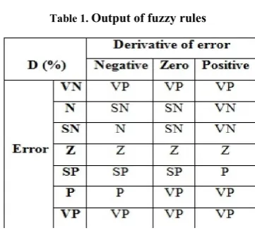
Table 1. Output of fuzzy rules
In the proposed fuzzy controller, totally 21 rules are formed and it shown in table 2. For example, if the error is positive and change in error is negative then the duty cycle will be positive. The rules formed process is called as fuzzification. After the fuzzification process, Defuzzification as a plant usually requires a non- fuzzy value of control, a defuzzification stage is needed. To compute the output modifies of the fuzzy logic controlled method is used and the fuzzy logic controller controls the switch in the inverter. In UPQC, the active power, reactive power, terminal voltage of the line and capacitor voltage are required to be maintained. In order to control these parameters, they are sensed and compared with the reference values. To achieve this, the membership functions of fuzzy controller.
U= -[ Αe+(1-α)*C]
[image:2.595.48.286.391.562.2]Proposed topology – IPM synchronous generator model & proposed controlling
The machine model in reference frame, which is synchronously rotating with the rotor, where -axis is aligned with the magnet axis and axis is orthogonal to - axis, is usually used for analyzing the interior permanent magnet
(IPM) synchronous machine. The - and – axes voltages of
PMSG can be given by
= − − + (1)
= − + + (2)
The d-and q-axes flux linkages are given by
=− + (3)
=− (4)
The torque equation of the PMGG can be written as
= P ( − ) = P ( + ( − ) (5)
In(1)–(5), , , , , and are the -and –axes stator
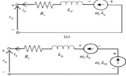
[image:3.595.69.536.52.248.2]voltages, currents, and inductances, respectively, is the stator resistance, is the rotor speed in rad/s, is the magnet flux, is the number of pole pairs, and is the operator. Fig. 5 shows the model of IPM synchronous generator.
[image:3.595.314.556.276.415.2]Fig.4. model of IPM synchronous generator: (a) -axis equivalent circuit and (b) -axis equivalent circuit
Fig.5. Proposed direct control scheme for the IPM generator side converter
Term in the torque equation (5) is the excitation torque that is produced by the interaction of permanent magnet flux and
and is independent of . The second term is the reluctance
torque that is proportional to the product of and and to the
difference between and . For the surface PMSG, the
reluctance torque is zero since = , while for the IPM
synchronous generator, higher torque can be induced for the
same and , if ( − ) is larger. This is one of the
advantages of IPM synchronous generator over surface PMSG.
The - and -axes current references can be expressed as
∗= ∗
[ ( )] (6)
∗ =
( ) - ( )+ (
∗ ) (7)
Proposed topology – direct control scheme for IPM synchronous generator
[image:3.595.63.284.643.775.2]The direct control scheme for IPM synchronous generator is shown in Fig. 6. In this scheme, current controllers are not used. Instead, the flux linkage and torque are controlled directly. The torque and flux are controlled using two hysteresis controllers and by selecting optimum converter switching modes, as shown in Fig. 6. The selection rule is made to restrict the torque and flux linkage errors within the respective torque and flux hysteresis bands to achieve the desired torque response and flux linkage. The required
switching-voltage vectors can be selected by using a switching voltage vector lookup table, as shown in Table 1. The selection of the voltage space vectors can be determined by the position of the stator flux linkage vector and the outputs of the two hysteresis comparators. The hysteresis control blocks compare the torque and flux references with estimated torque and flux, respectively. When the estimated torque/flux drops below its differential hysteresis limit, the torque/flux status output goes high. When the estimated torque/ flux rise above differential hysteresis limit, the torque/flux output goes low. The differential limits, switching points for both torque and flux, are determined by the hysteresis bandwidth. The appropriate stator voltage vector can be selected by using the switching logic to satisfy both the torque and flux status outputs. There are six voltage vectors and two zero voltage vectors that a voltage source converter can produce. The combination of the hysteresis control block (torque and flux comparators) and the switching logic block eliminates the need for a traditional PW modulator. The optimal switching logic is based on the
mathematical spatial relationships of stator flux, rotor flux ,
stator current, and stator voltage. These relationships are
shown in Fig.6 as rotor reference, stator flux ( ) reference,
and stationary reference frames. The angle between the stator
and rotor flux linkages ( ) is the load angle if the stator
resistance is neglected. In the steady state , is constant
[image:4.595.316.558.217.363.2]corresponding to a load torque and both stator and rotor fluxes rotate at the synchronous speed. In the transient operation, varies and the stator and rotor fluxes rotate at different speeds. The magnitude of the stator flux is normally kept as constant as possible, and the torque is controlled by varying the angle between the stator flux vector and the rotor flux vector.
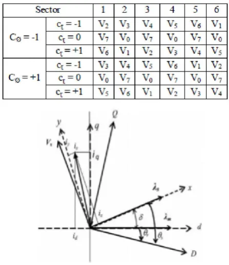
[image:4.595.314.555.409.555.2]Table 2. Six-vector switching table for converter
Fig.6. Stator and rotor flux linkages in different reference frame
Proposed topology – control of stator flux linkage by selecting proper stator voltage vector
The stator voltage vector for a three-phase machine with balanced sinusoid ally distributed stator windings is defined by the following equation:
= ( + + ) (8)
Where the phase axis is taken as the reference position and is the instantaneous values of line to neutral voltages. In Fig.7, the ideal bidirectional switches represent the power switches with their ant parallel diodes. The primary voltages and are determined by the status of these three switches. Therefore,
there are six nonzero voltage vectors (100),
(110), ……….and (101) and two zero voltage
vectors (000) and .(111) The six nonzero voltage vectors
are 60 apart from each other, as in Fig.8. These eight voltage vectors can be expressed as
( , , ) = ( + + / ) (9)
Fig. 7. Rectifier connected to IPM synchronous generator
Fig. 8. Available stator voltage vectors
[image:4.595.50.274.444.703.2]Fig. 9. Control of the amplitude of stator flux linkage
For example, when is in region and is rotating in the clockwise direction the voltage vectors pair and are selected to reverse the rotation of. B. Control of Rotation of The effect of two nonzero voltage vectors and is more complicated. It is seen that will stay at its original position when zero voltage vectors are applied. This is true for induction machine since the stator flux linkage is uniquely determined by the stator voltage, where the rotor voltages are always zero. In the case of an IPM synchronous generator, will change even when the zero voltage vectors are applied, since magnet flux continues to be supplied by the rotor and it will rotate with the rotor. In other words, should always be in motion with respect to the rotor flux linkage. Therefore, zero voltage vectors are not used for controlling in IPM synchronous machine.
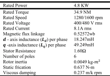
[image:5.595.95.513.233.783.2]Table 3. Parameter 0f IPM Synchronous Generator
Rated Power 4.8 KW
Rated Torque 34.9 NM
Rated Speed 1280/1600 rpm
Rated Voltage 400/480 V rms
Rated Current 8.1A rms
Magnetic flux linkage 0.52572wb
- axis inductance ( ) per phase 18.247mH -axis inductance ( ) per phase 49.249mH
Stator Resistance 1.60Ω
Number of poles 6
Rotor inertia 0.0049
kg-Static frication 0.637 N-m
Viscous damping 0.237 m/k rpm
The electromagnetic torque is controlled by controlling the direction of rotation of, according to the torque equation. For counter clockwise operations, if the actual torque is smaller than the reference value, the voltage vectors that keep rotating in the same direction are selected. The angle increases as fast as it can and the actual torque increases as well. Once the actual torque is greater than the reference value, the voltage vectors that keep rotating in the reverse direction are selected instead of the zero voltage vectors. The angle decreases and torque decreases too. By selecting the voltage vectors in this way, is rotated all the time and its rotational direction is determined by the output of the hysteresis controller for the torque. The six-vector switching table for controlling both the amplitude and rotating direction of is shown in Table 1 and is used for both the directions of operations. In Table 1, and are the outputs of the hysteresis controllers for flux linkage and torque, respectively. If, then the actual flux linkage is smaller than the reference value. The same is true for the torque. – are the region numbers for the stator flux linkage positions.
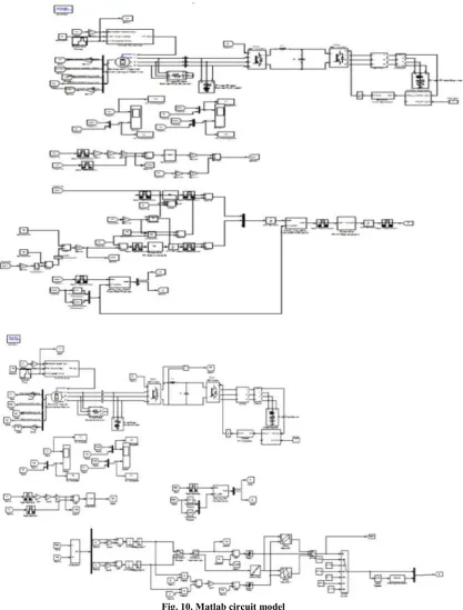
Matlab based simulation & Results discussion
The direct control scheme for IPM synchronous generator based variable speed wind turbine shown in Fig. 3 is implemented in MATLAB/ Sim Power Systems dynamic system simulation software. The IPM synchronous generator data are given in Table 3. Table 1 is used for switching the converter. The bandwidths of torque and flux hysteresis controllers are 10% of their rated values. A smaller hysteresis Band width can reduce ripples in torque. The sampling time s for the torque and speed control loops is 10 and 100μs, respectively. For comparisons, the traditional vector-controlled scheme shown in Fig. 1 has also been implemented in MATLAB /Sim Power Systems using the same IPM synchronous generator. MATLAB/Sim Power Systems wind turbine model is used in this work. The input to the wind turbine model is wind speed and the output is torque
[image:6.595.69.256.70.199.2]
Fig. 11. Performance of the traditional indirect vector control scheme: (a) wind speed, (b) q-axis current and its reference
Fig 12. (c) d-axis current and its reference, and (d) speed reference and measured speed
Fig. 13. Flux linkage and its reference, and (d) speed reference and measured
Conclusion
This paper proposed Modeling of IPM Synchronous Generator by Using Fuzzy Logic Controller Under variable Speed, no rotor position is required as all the calculations are done in stator reference frame. The proposed direct control scheme possesses several advantages compared with indirect vector control scheme, such as:
1) Lesser parameter dependence;
2) torque and flux control without rotor position and PI controller which reduce the associated delay in the controllers; and 3) sensorless operation without mechanical sensor. The results show that the direct controller can operate under varying wind speeds. However, direct control scheme has the problem of higher torque ripple that can introduce speed ripples and dynamic vibration in the power train. The methods to minimize the torque/ speed ripples need to be addressed. The simulation and experimental results for the sensorless speed estimator are presented, and the results show that the estimator can estimate the generator speed quite well with a very small error.
REFERENCES
Bhende, C.N., S.Mishra and S.G.Malla, 2011. “Permanent magnet synchronous generator based standalone wind energy supply system,” IEEE Trans. Sustain. Energy, vol. 2, no. 4, pp. 361–373, Oct.
Chan T. F. and L. L. Lai, 2007. “Permanent-magnet machines for distributed generation: A review,” IEEE Power Engg. Annual Meeting, Tampa, FL, USA, Jun. 24–28, pp. 1–6. Chinchilla, M., S.Arnaltes and J.C.Burgos, 2006. “Control of
permanent-magnet generators applied to variable-speed wind-energy systems connected to the grid,” IEEE Trans. Energy Convers., vol. 21, no. 1, pp. 130–135, Mar. Deghan, S.M., M.Mohamadian and A.Y. Varjani, 2009.
[image:6.595.309.557.217.327.2] [image:6.595.40.285.673.774.2]Z-source inverter,” IEEE Trans. Energy Convers., vol. 24, no. 3, pp. 714–724, Sep.
Esmali R. and L. Xu, 2006. “Sensorless control of permanent magnet generator in wind turbine application,” IEEE Industry Applications Society Annual Meeting, Tampa, FL, USA, Oct. 8–12, pp. 2070–2075.
Haque, M.E., M.Negnevitsky and K.M.Muttaqi, 2010. “Anovelcontrolstrategy for a variable-speed wind turbine with a permanent-magnet synchronous generator,” IEEE Trans. Ind. Appl., vol. 46, no. 1, pp. 331–339, Jan./Feb. Hu, J., H.Nian, H.Xu and Y.He, 2011. “Dynamic modeling and
improved control of DFIG under distorted grid voltage conditions,” IEEE Trans. Energy Convers., vol. 26, no. 1, pp. 163–175, Mar.
Kazmi, S.M.R., H.Goto, H.J.Guo and O.Ichinokura, 2011. “Anovelalgorithm for fast and efficient speed-sensorless maximum power point tracking in wind energy conversion systems,” IEEE Trans. Ind. Electron., vol. 58, no. 1, pp. 29–36, Jan.
Mohseni, M., M. S. M. Islam, and M. A. Masoum, “Enhanced hysteresisbased current regulators in vector control of DFIG wind turbine,” IEEE Trans. Power Electron., vol. 26, no. 1, pp. 223–234, Jan. 2011.
Morimoto, S., H.Nakayama, M.Sanada and Y.Takeda, 2005. “Sensorless output maximization control for variable-speed wind generation system using IPMSG,” IEEE Trans. Ind. Appl., Vol.41, No.1, pp.60–67, Jan./Feb.
Müller, S., M. Deicke, and R. W. D. De Doncker, “Doubly fed induction generator system for wind turbines,” IEEE Ind. Appl. Mag., vol. 8, no. 3, pp. 26–33, May 2002.
Nishida, K., T. Ahmed, and M. Nakaoka, 2011. “A cost-effective high-efficiency power conditioner with simple MPPT control algorithm for wind-power grid integration,” IEEE Trans. Ind. Appl., vol. 47, no. 2, pp. 893–900, Mar.
Polinder, H., F. F. A. Van der Pijl, G. J. de Vilder, and P. J. Tavner, 2006. “Comparison of direct-drive and geared generator concepts for wind turbines,” IEEE Trans. Energy Convers., vol. 3, no. 21, pp. 725–733, Sep.
Qiao, W., L. Qu and R. G. Harley, 2009. “Control of IPM synchronous generator for maximum wind power generation considering magnetic saturation,” IEEE Trans. Ind. Appl., vol. 45, no. 3, pp. 1095–1105, May/Jun. Rahman, M. F., L. Zhong, and K. W. Lim, 1998. “A direct
torque controlled interior permanent magnet synchronous motor drive incorporating field weakening,” IEEE Trans. Ind. Appl., vol. 34, no. 6, pp. 1246–1253, Nov.
Takahashi I. and T. Noguchi, 1986. “A new quick response and high efficiency control strategy of an induction motor,” IEEETrans.Ind.Appl., Vol.IA-22, No. 5, pp. 820–827, Sep. Takahashi I. and Y.Ohmori, 1989. “High-performance direct torque control of an induction motor,” IEEE Trans. Ind. Appl., vol.25,no.2,pp.257–264,Mar./ Apr. 1989.
Uehara, A., A. Pratap, T. Goya, T. Senjyu, A. Yona, N. Urasaki, and T. Funabashi, 2011. “A coordinated control method to smooth wind power fluctuation of a PMSG-based WECS,” IEEE Trans. Energy Convers., vol. 26, no. 2, pp. 550–558, Jun.
Zhang, S., K.J.Tseng, D.M.Vilathgamuwa, T.D.Nguyen and X.Y.Wang, 2011. “Design of a robust grid interface system for PMSG-based wind turbine generators,” IEEE Trans. Ind. Electron., vol. 58, no. 1, pp. 316–328, Jan.
Zhong, L., M.F.Rahman and K.W.Lim, 1997. “Analysis of direct torque control in permanent magnet synchronous motor drives,” IEEE Trans. Power Electron., vol. 12, no. 3, pp. 528–536, May.