Mohammad A. Ghadamyari1, *, Mehdi Moallem1, and Babak Fahimi2
Abstract—In this paper, a novel technique for improving the torque characteristics of the Interior Permanent Magnet Synchronous Motor is proposed using rotor shape optimization. The main objective is to decrease the torque ripple while increasing average torque. The improvement process is performed for the maximum torque-angle operating point, and then studies are carried for other currents and angles. Defining a multi-element grid on rotor surface regions in which each element could be either iron or air, the best practical rotor surface topology could be obtained to improve the overall torque characteristics of IPMSM. The best motor performance is achieved using practical rotor shapes obtained from a cluster of points in average torque versus torque ripple plane. Finally, for torque ripple cancellation, two or three alternate rotor configurations with optimized average torque and out of phase torque pulsation have been selected. This selection will guarantee improved average torque while mitigating torque pulsation by a significant margin. Using this method, a rotor topology obtained in which torque ripple is reduced by 80% with slightly improved average torque.
1. INTRODUCTION
Interior permanent magnet synchronous machine (IPMSM) is one of the best candidates for industrial, domestic and electrical transportation applications thanks to its special advantages such as high power density and efficiency, good controllability over a wide range of speeds and fast dynamic response. During the last two decades, many efforts have been made to improve IPMSM’s performance by choosing proper number of phases, poles and slots combination, winding configurations, better control strategies and also shape optimization of rotor and stator.
To further enhance its performance, in [1, 2] an asymmetrical V-shape rotor configuration of an interior pm machine for improving the toque characteristics is presented. In [3] a novel cogging torque mitigation technique for modular pm machines is presented using a shifting in slot opening. A rotor skew pattern design is proposed in [4] for cogging torque reduction. Different patterns of skewing on an interior pm machine is well considered at this work. In [5] an optimal design procedure for optimization of rotor shape of a spoke-type IPMSM is presented and torque ripple is reduced by about 5 percent. In [6] a torque ripple reduction for IPMSM is achieved using stators with odd number of slots per pole pairs. It indicates that torque ripple can be reduced to less than 5 percent using this methodology. In [7], a novel rotor design has been developed to reduce iron loss over a wide speed range. It shows a reduction of 20 percent in iron loss, whereas maximum torque is decreased by 4 percent too. In [8] local forces on stator teeth and consequently natural frequencies and normal modes of stator are calculated. Design optimization is then performed to reduce the noise and vibration. Similar efforts have been made on shape optimization of the rotor, stator and/or permanent magnets to improve the motor characteristics in [9–17]. In [18–22] some efforts are made to study the local forces in surface mounted permanent magnet motor, switched reluctance motor and a simple electromagnetic device. However, a systematic
Received 24 December 2016, Accepted 19 January 2017, Scheduled 8 February 2017
* Corresponding author: Mohammad Adib Ghadamyari ([email protected]).
1 Department of Electrical and Computer Engineering, Isfahan University of Technology, Iran. 2 Department of Electrical and
approach is needed to improve the motor performance based on these observations. An extended field reconstruction method for modeling of the studied machine of this paper is proposed considering both saturation and slotting effects in [23].
In this study, rotor surface shape is improved to reduce the torque ripple by a large margin with improved or without negative effect on average torque. The proposed method uses a matrix of elements on the surface of rotor which is the most sensitive regions of the rotor regarding the torque ripple due its vicinity to air gap.
Reshaping of the rotor surface is based on a multi-element grid chosen around each air-bridge. The best motor performance is achieved using rotor shapes obtained from a cluster of points in average torque versus torque ripple plane. Finally, for torque ripple cancellation, a novel reshaping method considering two different geometries of rotor shapes with counteracting torque pulsations is used. Using this method, torque ripple is reduced by about 80% without negative effect on average torque.
2. MODELING THE INITIAL MACHINE
A conventional IPMSM is adopted as the basic model for this study. The stator has 36 slots, with two windings per pole per phase. The NdFeB magnets are buried completely in the rotor iron and there is
Figure 1. Cross section of original design. Figure 2. Rotor of the IPMSM motor with shifted stacks.
Table 1. Motor specifications.
Output power 1 hp Stator outer diameter 139 mm
Stator inner diameter 85.7 mm Length of stack 50.8 mm slot depth 12.54 mm
Tooth width 3.57 mm No of slots 36 Slot opening 2.3 mm
No of winding turns 68 Rotor outer diameter 84 mm Rotor inner diameter 50.2 mm
No of poles 6 PM relative permeability 1.0297 T PM Coercivity −796000 A/m
PM thickness 2.54 mm
PM width 16.2 mm
gap between magnets 0.8 mm
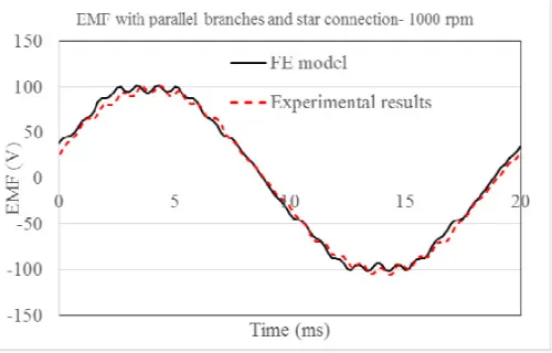
Figure 3. Calculated and measured back-EMF.
Figure 4. Calculated and measured static torque (Ia= 2, Ib=Ic=−1).
a 4 degree skewing shift between two rotor stacks. In the proposed topology, the skew effect is removed and just the rotor shape modification is used to improve the torque performance. Fig. 1 shows the cross sectional view of the IPMSM and Fig. 2 shows the rotor construction. Table 1 lists the motor specifications.
However, in this paper, a 2D time stepping finite element model is used for steady state analysis of the machine. Fig. 3 shows the measured and calculated back-EMF profile at 1000 rpm and a good match between the FE model and experimental results can be observed. Due to a 4 degrees shift between rotor stacks, the results of one stack are shifted and the summation is considered for the machine. As mentioned earlier, in the optimization process, this shifting is removed and the performance improvement is done using the rotor shape optimization. Skewing is a great solution to reduce the torque pulsation and harmonics and to have a smoother back-EMF, however, it has some negative effects on reducing the average torque and fundamental back-EMF as well as manufacturability and cost.
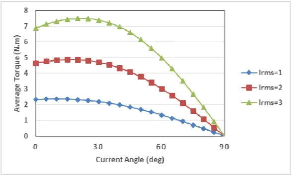
Using a 2D finite element model and injecting a 2 A dc current (Ia = 2, Ib = −1, Ic = −1) to the stator conductors and rotor locked condition, the profile of torque for different positions of rotor is calculated and measured by experimental setup. Fig. 4 shows the good precision of provided FE model. Torque profile is then calculated for different current levels and current angles with the star connection and all windings in series. Fig. 5 shows the average torque for three current levels in different current angles and Fig. 6 shows the torque ripple for the same data. Torque ripple is defined as [(Tmax−Tmin)/Tave∗100] whichTmax is the maximum torque,Tminis the minimum torque, andTave
Figure 5. Torque characteristic of machine in different current amplitude and angles.
Figure 6. Torque ripple of machine in different current amplitude and angles.
3. MULTI-ELEMENT METHOD FOR SHAPE IMPROVEMENT
Rotor surface shape is one of the most effective factors on the normal and tangential force components. For this reason, a multi-element grid of quasi-rectangular shaped arrays is constructed on the rotor surface to find the best arrangement of iron-air combination. The discretized region comprises of a single layer in the rotor surface and each element could be changed from air to iron.
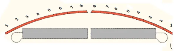
Figure 7 shows a single-layer multi-element model containing 16 elements for each pole. Thanks to the symmetry, each pole could be divided to two semi pole with the similar patterns which shown with similar numbered elements on the surface of rotor.
In the proposed layer, with changing the material of these eight elements (0 for air and 1 for iron), various combinations of air-iron elements are available. Consequently, for a complete investigation, 28 = 256 different permutations are at hand. For each permutation, the rotor should be rotated 60 degrees (with one degree steps) to calculate maximum, minimum, average and ripple of the electromagnetic torque in a half electric cycle.
To find the best rotor shape, 256 different combinations are solved using transient finite element method.
Figure 7. Numbering of rotor surface elements.
Figure 8. Average torque versus torque ripple of 256 problems.
Table 2. Element arrangement for design No. 160.
Element No. 1 2 3 4 5 6 7 8
Material 1 0 0 1 1 1 1 1
Table 3. Comparison of performances of initial design and design No. 160.
Objective Initial Rotor Rotor No. 160 Improvement (%)
Average (N·m) 4.84 5.06 4.5% increase
Ripple (%) 32.9 28.27 15% reduction
Figure 9. Cross section of design No. 160.
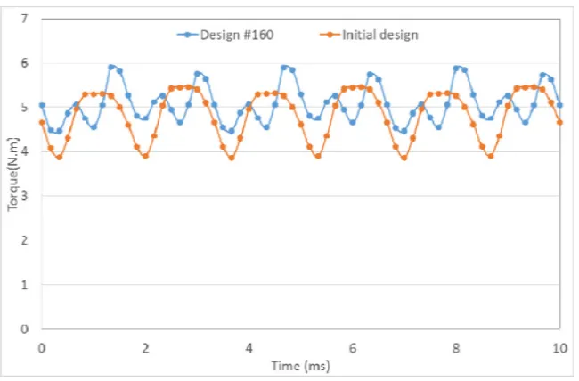
Figure 10. Torque profile of design No. 160 and initial design.
Design No. 160 is chosen as the best design thanks to its highest average torque and lower ripple than initial design. Table 2 shows the arrangement of elements for the considered layer and Fig. 9 shows the torque profile for initial design and design No. 160. Fig. 10 presents the torque profile for initial design and design No. 160. In Table 3, the performance of this design is compared with results obtained for initial design. Using the surface layer optimization, in addition to 4.5% increase in average torque, torque ripple is reduced by about 15%. Using this method, it is possible to significantly reduce the torque ripple and increase the average torque at the same time.
It is possible to find designs with lower average torque as well as lower torque ripple. Choosing the best design is a tradeoff between average torque and torque ripple which depends on the application. It is possible to find the best desired design using weighting factors for each objective parameter.
4. TORQUE RIPPLE CANCELLATION
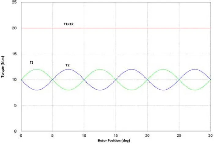
Figure 11. Torque ripple cancelation.
Figure 12. Average torque versus torque ripple for combined designs.
shows how this idea works; T1 and T2 are the torque profile of two designs with similar patterns but opposite swinging and in the case of complete sinusoidal torque profile, theoretically ripple will be canceled completely.
pairs in post-processing. There will be 32640 distinct configurations of combined shapes. Calculating the average torque and torque ripple of these entire configuration shows that there exist several distinct shapes which will be able to cancel torque ripple without any negative effect on the average torque. Fig. 12 shows entire possible configurations of the combined designs. Dashed lines present the average torque and torque ripple of initial design and the upper left zone shows all designs with better
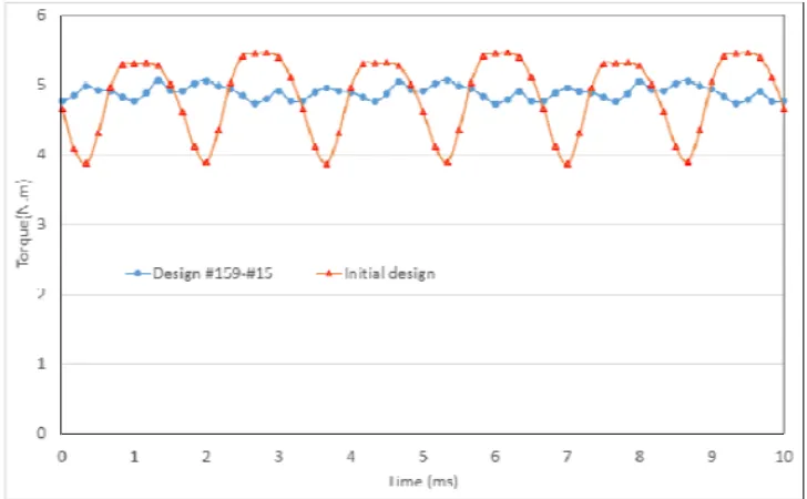
Figure 13. Torque profile of initial design and combined design 159-15.
Figure 14. Rotor surface element rearrangement.
Table 4. Comparison of combined and initial designs.
Objective Initial Rotor Combination of No. 15 & No. 159 Improvement (%)
Average (N·m) 4.84 4.88 1% increase
Figure 15. Average torque comparison between improved and initial design.
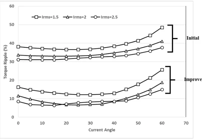
Figure 16. Torque-ripple comparison of initial and improved design.
performance. It is possible to find significant number of configurations with higher average torque and lower torque ripple.
Table 3 shows the performance of combination of design No. 15 and design No. 159. Combining this two high average torque designs, a new design with the same average torque and much smaller torque ripple is available.
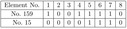
Table 5. Element arrangement of design No. 15 and No. 159.
Element No. 1 2 3 4 5 6 7 8
No. 159 1 0 0 1 1 1 1 0
No. 15 0 0 0 0 1 1 1 0
surface is divided into four zones with the shown arrangement of each zone in Table 5. Fig. 13 shows the torque profile of combined and initial design. As shown in Table 4, with this method, 80% reduction in torque ripple is provided for the studied point with no negative impact on average torque.
The optimization process is done for the current of 2 A and current angle of 20 deg. To be sure that the process is working well for other operational points, three current levels for various angles is considered. Fig. 15 presents three current levels of 1.5, 2, and 2.5 A and angle range between 0 and 90 degree. At 2.5 currents and in the high current angles which normally occurs in field weakening, average torque is reduced around 1%. On the other hand, new design has better performance around the studied zone. Fig. 16 presents the torque ripple around the studied zone the best torque ripple cancelation is achieved.
5. CONCLUSION
In this study, based on the rotor surface shape improvement of an IPMSM, the most effective regions for an improved torque profile have been identified. A multi-element grid is proposed around the air gap on the rotor surface. All possible configurations for the choice of air or iron are studied. It is shown that using this method, in some designs, the average torque can be increased, yet the torque ripple is still high. It is possible to find a few designs with high reduction in torque ripple, yet with lower average torque. To overcome the conflict between average torque increase and torque ripple reduction, a novel torque ripple cancellation technique based on using two different rotor surface shape configurations with out of phase torque ripple behavior is proposed. Using the single layer topology, it is possible to reduce torque ripple significantly without losing higher average torque. New design shows 80% decrease in torque ripple compared to the initial design without losing the average torque. The effectiveness of this method is also shown for various current amplitudes and current angles.
REFERENCES
1. Ren, W., Q. Xu, and Q. Li, “Asymmetrical V-shape rotor configuration of an interior permanent magnet machine for improving torque characteristics,” IEEE Transactions on Magnetics, Vol. 51, No. 11, Nov. 2015.
2. Yoon, M. H., D. Y. Kim, S. I. Kim, and J. P. Hong, “An asymmetric rotor design of interior permanent magnet synchronous motor for improving torque performance,” Journal of Magnetics, Vol. 20, No. 4, 387–393, 2015.
3. Li, G. J., B. Ren, Z. Q. Zhu, Y. X. Li, and J. Ma, “Cogging torque mitigation of modular permanent magnet machines,”IEEE Transactions on Magnetics, Vol. X, 2015.
4. Jiang, J. W., B. Bilgin, Y. Yang, A. Sathyan, H. Dadkhah, and A. Emadi, “Rotor skew pattern design and optimization for cogging torque reduction,” IET Electrical Systems in Transportation, 2015.
5. Hwang, K. Y., J. H. Jo, and B. I. Kwon, “A study on optimal pole design of spoke-type IPMSM with concentrated winding for reducing the torque ripple by experiment design method,” IEEE Transactions on Magnetics, Vol. 45, No. 10, 4712–4715, Oct. 2009.
Vol. 47, No. 10, 3020–3023, Oct. 2011.
10. Abbasian, M. A., M. Moallem, and B. Fahimi, “Double-Stator Switched Reluctance Machines (DSSRM): Fundamentals and magnetic force analysis,”IEEE Transactions on Energy Conversion, Vol. 25, No. 3, 589–597, 2010.
11. Yamazaki, K., Y. Kanou, Y. Fukushima, S. Ohki, and A. Nezu, “Reduction of magnet eddy-current loss in interior permanent-magnet motors with concentrated windings,” IEEE Transactions on Industry Applications, Vol. 46, No. 6, 2434–2441, Nov.–Dec. 2010.
12. Alotto, P., M. Barcaro, N. Bianchi, and M. Guarnieri, “Optimization of interior PM motors with machaon rotor flux barriers,”IEEE Transactions on Magnetics, Vol. 47, No. 5, 958–961, May 2011. 13. Ishikawa, T., M. Yamada, and N. Kurita, “Design of magnet arrangement in interior permanent magnet synchronous motor by response surface methodology in consideration of torque and vibration,”IEEE Transactions on Magnetics, Vol. 47, No. 5, May 2011.
14. Kim, H. S., Y. M. You, and B. Kwon, “Rotor shape optimization of interior permanent magnet BLDC motor according to magnetization direction,” IEEE Transactions on Magnetics, Vol. 49, No. 5, 2193–2196, May 2013.
15. Fei, E. W. and P. C. K. Luk, “Torque ripple reduction of a direct-drive permanent-magnet synchronous machine by material-efficient axial pole pairing,” IEEE Transactions Industrial Electronics, Vol. 59, No. 6, 2601–2611, 2011.
16. Suja, F. R. and P. Melba Mary, “Minimization of torque ripples in permanent magnet synchronous motor-overview,” International Journal of Scientific & Engineering Research, Vol. 4, No. 10, Oct. 2013.
17. Richnow, D. J., D. Gerling, and P. Stenzel, “Torque ripple reduction in permanent magnet synchronous machines with concentrated windings and pre-wound coils,” 2014 17th International Conference on Electrical Machines and Systems (ICEMS), Hangzhou, China, Oct. 22–25, 2014. 18. Zhu, W., S. Pekarek, B. Fahimi, and B. J. Deken, “Investigation of force generation in a permanent
magnet synchronous machine,”IEEE Transactions on Energy Conversion, Vol. 22, No. 3, 557–565, Sep. 2007.
19. Jiang, W., S. Pekarek, B. Fahimi, and B. J. Deken, “Investigation of force generation in a permanent magnet synchronous machine,”IEEE Transactions on Energy Conversion, Vol. 22, No. 3, Sep. 2007. 20. Jiang, W., M. Moallem, B. Fahimi, and S. Pekarek, “Qualitative investigation of force density
components in electromechanical energy conversion process,”IECON, 2006.
21. Ghadamyari, M. A., M. Moallem, B. Fahimi, and M. McDonough, “Micro-analysis of electromagnetic force distribution in a simple actuator,” 19th International Conference on Computation of Electromagnetic Fields (COMPUMAG), 2013.
22. Kiomarsi, A., M. Moallem, and B. Fahimi, “Mitigation of torque ripple in interior permanent magnet motors via optimal shape design,” IEEE Transactions on Magnetics, Vol. 42, No. 11, Nov. 2006.