Western University Western University
Scholarship@Western
Scholarship@Western
Electronic Thesis and Dissertation Repository
8-20-2015 12:00 AM
Modern Optimization Algorithms and Applications: Architectural
Modern Optimization Algorithms and Applications: Architectural
Layout Generation and Parallel Linear Programming
Layout Generation and Parallel Linear Programming
Bradley J. de VlugtThe University of Western Ontario
Supervisor
Dr. Abdallah Shami
The University of Western Ontario Joint Supervisor Dr. Serguei Primak
The University of Western Ontario
Graduate Program in Electrical and Computer Engineering
A thesis submitted in partial fulfillment of the requirements for the degree in Master of Engineering Science
© Bradley J. de Vlugt 2015
Follow this and additional works at: https://ir.lib.uwo.ca/etd
Part of the Other Electrical and Computer Engineering Commons
Recommended Citation Recommended Citation
de Vlugt, Bradley J., "Modern Optimization Algorithms and Applications: Architectural Layout Generation and Parallel Linear Programming" (2015). Electronic Thesis and Dissertation Repository. 3208.
https://ir.lib.uwo.ca/etd/3208
This Dissertation/Thesis is brought to you for free and open access by Scholarship@Western. It has been accepted for inclusion in Electronic Thesis and Dissertation Repository by an authorized administrator of
ARCHITECTURAL LAYOUT DESIGN AND PARALLEL LINEAR
PROGRAMMING
(Thesis format: Integrated Article)
by
Bradley de Vlugt
Graduate Program in Electrical and Computer Engineering
A thesis submitted in partial fulfillment
of the requirements for the degree of
Master of Engineering Science
The School of Graduate and Postdoctoral Studies
The University of Western Ontario
London, Ontario, Canada
c
Acknowlegements
I would like to acknowledge Dr. Maysam Mirahmadi and my advisors, Dr. Abdallah
Shami and Dr. Serguei Primak, for their mentorship throughout this thesis. I am grateful for
the creativity and wisdom they shared to help me grow as a researcher. I would like to thank
my fellow lab members for their friendship during this rewarding and challenging endeavor.
I would also like to thank my thesis defence committee for their insightful comments and
suggestions.
To my parents, Lori and Paul de Vlugt, thank you for your guidance and encouragement.
This thesis would not have been possible without you both. To my brother, Jeffde Vlugt, thank you for the jam sessions and helping me think outside the box. To my girlfriend, Carolyn
Bolger, thank you for all of your love and amazing carrot cake cupcakes. To Kevin Brightwell,
thank you for the interesting software design discussions and best wishes with your academic
pursuits. And to all my colleagues, friends and family, thank you for your support throughout
this work.
This thesis examines two topics from the field of computational optimization; architectural
layout generation and parallel linear programming. The first topic, a modern problem in
heuris-tic optimization, focuses on deriving a general form of the optimization problem and solving
it with the proposedEvolutionary Treemapalgorithm. Tests of the algorithm’s implementation
within a highly scalable web application developed with Scala and the web service framework
Play reveal the algorithm is effective at generated layouts in multiple styles. The second topic, a classical problem in operations research, focuses on methodologies for implementing the
Sim-plex Algorithm on a parallel computer for solving large-scale linear programming problems.
Implementations of the algorithm’s data-parallel and task parallel forms illuminate the ideal
method for accelerating a solver. The proposedMulti-Path Simplex Algorithmshows an
aver-age speed up of over two times that of a popular open-source solver, showing it is an effective methodology for solving linear programming problems.
Keywords: Genetic Algorithms, Procedural Generation, Architecture, Treemap, Linear
Programming, OpenCL, Simplex Algorithm, Parallel Computing
Contents
Acknowlegements ii
Abstract iii
List of Figures viii
List of Tables x
List of Appendices xi
1 Introduction 1
1.1 Background . . . 1
1.1.1 Architectural Layout Generation . . . 2
1.1.2 The Simplex Algorithm . . . 3
1.2 Contributions . . . 4
1.2.1 Architectural Layout Generation . . . 4
1.2.2 Parallel Linear Programming . . . 4
2 Architectural Layout Generation With Evolutionary Treemap 8 2.1 Introduction . . . 8
2.2 Literature Review . . . 9
2.3 Formulating the Layout Generation Problem . . . 12
2.3.1 The Standard Form . . . 12
2.3.2 The Solution Space . . . 14
2.3.3 The Generator Function . . . 16
2.3.4 Optimizer Functions . . . 17
2.4 Evolutionary Treemap . . . 18
2.4.1 Rectified Treemap . . . 19
2.4.2 Corridor Placement . . . 21
2.4.3 Evolutionary Optimization . . . 23
2.4.4 Measuring the Cost Value . . . 24
2.5 System Design and Implementation . . . 25
2.5.1 Representation of the User Specification . . . 27
2.5.2 Software Library Architecture . . . 28
2.5.3 API Design . . . 29
2.6 Discussion . . . 31
2.6.1 Office Buildings . . . 31
2.6.2 Open-Concept Residential Buildings . . . 33
2.6.3 Convergence Behavior . . . 35
2.6.4 Future Work . . . 35
Fixed Structures and Non-Rectangular Boundaries . . . 35
Corridor Optimizer Function . . . 39
Multi-Story Buildings . . . 40
2.7 Conclusion . . . 41
3 Parallel Linear Programming with Dense Data Structures 44 3.1 Introduction . . . 44
3.2 Literature Review . . . 45
3.3 Background . . . 47
3.3.1 The Dictionary Simplex Algorithm . . . 49
The Augmented Linear Programming Problem . . . 49
The Optimal BFS . . . 50
The Dictionary Data Structure . . . 51
The Initial Partition . . . 51
The Pricing Algorithm . . . 52
The Ratio Test . . . 52
The Pivot Algorithm . . . 53
The Size of the Dictionary . . . 53
3.4 Parallel Implementation of the Dictionary Algorithm . . . 55
3.4.1 OpenCL Software Design Architecture . . . 56
3.5 Benchmarking Results . . . 57
3.5.1 Speed Up . . . 57
3.5.2 Performance versus Power . . . 59
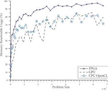
3.5.3 Memory Bandwidth . . . 60
3.5.4 Future Directions . . . 60
3.6 Conclusions . . . 62
4 Multi-Path Parallelism in the Simplex Algorithm 65 4.1 Introduction . . . 65
4.2 Literature Review . . . 66
4.3 Internal Parallelism Performance Bounds . . . 67
4.3.1 Profiling Methodology . . . 68
4.3.2 Computing Performance Limits . . . 68
4.4 The Multi-Path Simplex Algorithm . . . 71
4.4.1 Algorithm Configurations . . . 73
4.5 Profiling The Multi-Path Algorithm . . . 74
4.6 Discussion . . . 75
4.6.1 Future Directions . . . 78
4.7 Conclusion . . . 78
5 Conclusion 80 5.1 Intelligent Architectural Design . . . 80
5.2 Parallel Linear Programming . . . 81
5.3 Concluding Remarks . . . 82
A SoPlex Performance Data 84
Curriculum Vitae 120
List of Figures
2.1 A Functional Layout for an Office Building and the Architectural Design . . . . 8 2.2 Example Treemap Representation . . . 11
2.3 Different Mathematical Representations for a Single Room . . . 15 2.4 Visual example of the result in Lemma 2.3.4. Partitioning the final section into
the entrance and kitchen presents uncountably infinite possibilities betweeny= Pandy= Qify∈ R. . . 16 2.5 In larger layouts, applying the spanning tree algorithm eliminates redundant
edges in the corridor to minimize wasted space . . . 22
2.6 Effect of cost function parameters on the generated layout . . . 26 2.7 UML Diagram of the Layout Generation Software . . . 29
2.8 Two example office layouts generated by theEvolutionary Treemapalgorithm based on the specification in Table 2.3 . . . 32
2.9 Residential layouts generated by theEvolutionary Treemapalgorithm based on
the specification in Table 2.4 . . . 34
2.10 Convergence of Evolutionary Treemap over twenty generations for an office layout with a mutation rate of 0.08 and an elite rate of 0.01 . . . 36
2.11 An example layout with a non-rectangular boundary generated with the
aug-mentedEvolutionary Treemapalgorithm . . . 38
2.12 An example of a corridor that contains loops which may or may not be
neces-sary depending on the designer preferences . . . 39
3.1 Visualization of the feasible region in a simple linear programming problem
with two decision variables and four constraints. Arrows indicate a possible
Simplex path. . . 48
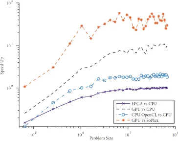
3.4 Speed up of the OpenCL dictionary algorithm over the sequential C++ algo-rithm . . . 58
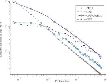
3.5 Device performance versus power analysis . . . 59
3.6 The estimated percentage of available memory bandwidth used by each device . 61
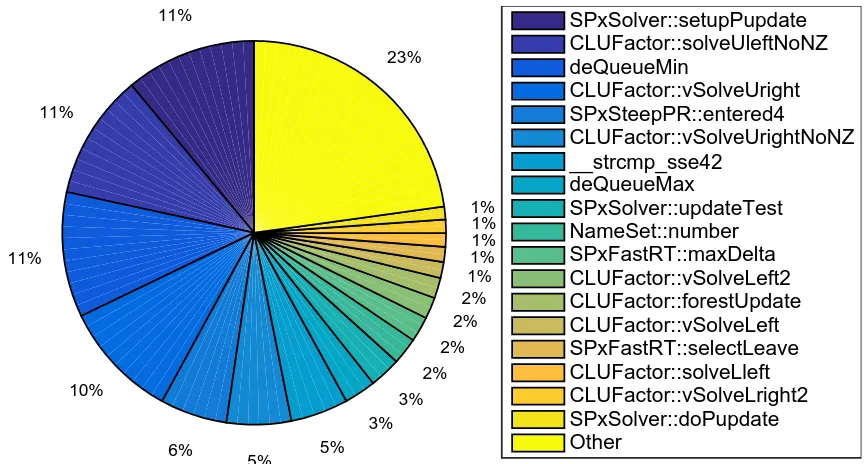
4.1 Distribution of algorithm runtime in SoPlex for the selected test problems . . . 69
4.2 Maximum possible speedup predicted by Amdahl’s Law . . . 70
4.3 Ratio of the time taken by SoPlex to the time taken by theMulti-Path Simplex
Algorithmfor the full data set . . . 76
4.4 Ratio of the time taken by SoPlex to the time taken by theMulti-Path Simplex
Algorithmfor problems with over 106elements . . . 77
List of Tables
2.1 Functional Layout Generation: Nomenclature for the General Form . . . 13
2.2 Web Service API . . . 30
2.3 Shape Specifications for the Rooms in the Medium Sized Office Layout . . . . 31 2.4 Shape Specifications for the Rooms in the Residential Home Layout . . . 33
3.1 Hardware Device Specifications . . . 57
A.1 SoPlex Runtime for Selected Linear Programming Test Cases . . . 85
A.2 Average Runtime of SoPlex Functions over Selected Linear Programming Test
Cases from Perf Profiling Reports . . . 96
B.1 Averaged Performance Results for Multi-Path Simplex versus SoPlex with
Ran-domly Selected Pricing Algorithms for 100 Trials . . . 109
SoPlex Performance Data . . . 84
Multi-Path Simplex Algorithm Performance Data . . . 108
Chapter 1
Introduction
Parallel and distributed computing systems present opportunities in the field of optimization
from the perspective of scale and speed in both modern and classical applications. This
the-sis presents three articles from two optimization applications that introduce new algorithms,
demonstrate scalable software design and enhance algorithms with parallelism. The first
ap-plication is architectural layout generation, a modern apap-plication of optimization that utilizes
stochastic algorithms to calculate the location and shape of rooms for a building floor plan. The
second is linear programming with the Simplex Algorithm, a classical optimization algorithm
that solves models with linear cost function, linear constraints and no integer variables. Both
of these applications are examined herein, culminating in a set of novel contributions for each
field that improve upon software performance and design. The topics are disjoint in nature but
share the common theme of optimization and algorithm design.
This thesis begins with a summary on the prerequisite information from linear
program-ming and architectural layout generation and refers interested readers to detailed texts.
Sum-maries of the main objectives and contributions of the document follow.
1.1
Background
Parallel linear programming and architectural layout generation have seen numerous notable
advancements since their conceptions and are both supported with large bodies of literature.
This section provides a brief review of the pertinent literature from both applications, leaving
detailed reviews to the respective chapters. The review begins with architecture generation and
concludes with theSimplex Algorithm.
1.1.1
Architectural Layout Generation
Industrial building renovation projects are performed by teams that consist of architects,
de-signers, engineers and clients. The projects require allocation of spaces within an existing
building by the architects and designers to meet building codes that are checked by the
engi-neers and design specifications that are checked by the client. The full design is specified with
a computer aided design (CAD) drawing that undergoes iterative refinement to ensure that all
specifications, both technical and artistic, are met before construction can occur.
Many tools are available to this industry for increasing the speed at which CAD
draw-ings can be produced. The first building design drawdraw-ings were conducted by hand on drafting
boards. This practice was soon replaced after the 1982 invention of AutoCAD [1] which
al-lowed formation of the layout drawings on a computer that could more quickly be used to
refine the drawings as specifications were revealed. Multiple such automated CAD tools such
as SolidWorks [2], Revit [3] and MicroStation [4] are now available for use in this industry to
accelerate projects. These software allow three dimensional modelling of entire construction
sites. AutoDesk now provides a cloud version of AutoCAD which allows users to edit
draw-ings in a web browser. The advancements in CAD software have greatly assisted the ability
of stakeholders in construction and renovation projects to react to changing requirements in a
design.
Functional layout generation is a modern topic in stochastic optimization, seeing its first
lit-erature in the 1990’s [5] following advancements in computer graphics and data visualization
methodologies. The majority of approaches in literature are based on stochastic optimization
techniques, which optimize a data structure through mutations and measure changes with a
heuristic cost function. For example, a recent technique proposed in literature generates
lay-outs with genetic optimization [6] on a tree data structure. Other techniques are based on
de-terministic algorithms, such asSquarified Treemap[7]. This field is in infancy relative to linear
1.1. Background 3
full solution for generating architectural layouts. The majority of these algorithms are tailored
towards generation of residential homes, leaving additional topologies that can be explored
through different formations of the problem with other optimization techniques.
1.1.2
The Simplex Algorithm
Linear Programming has been treated by numerous authors dating back to the discovery of the
Simplex Algorithmin the 1940’s by George Dantzig [8]. The algorithm transformed from the
initial form proposed by Dantzig to a highly efficient, optimized form through discoveries by authors such as Forrest [9], Tomlin [10], Maros [11], and many others, resulting in enhanced
efficiency and stability. The optimization can be used to solve models with linear objectives and constraints that appear in fields such as task scheduling, computer network design and
radiation therapy.
High performance forms of the algorithm are available for engineers as both commercial
packages, with IBM CPLEX [12], Gurobi [13], XPress [14], and open-source software, with
SoPlex [15], GLPK [16], Coin-OR [17], LpSolve [18]. These commercial and open-source
codes provide a wealth of opportunity for engineers to optimize linear programming models in
different applications. The support for parallel processor cores available in commercial codes, as seen by the parallel switch available in CPLEX [19], has yet to be realized in the open-source
code and is a resource available that could improve performance.
Recent efforts to parallelize the Simplex Algorithm have investigated performance of the algorithm on highly parallel processors such as Graphics Processing Units (GPUs) and Field
Programmable Gate Arrays (FPGAs). A study of the algorithm, operating with dense data
structures on randomly generated problems revealed that speed ups in the order of twenty times
are possible [20]. Another study that focused on implementation with FPGAs also showed
po-tential for performance improvements over traditional sparse codes [21]. Though these results
are promising, no author has implemented a parallel algorithm capable of solving the
numeri-cally challenging sparse problems found in practical modeling scenarios that shows good speed
up. This is a challenge due to the inherently sequential nature of the algorithm. It consists of
1.2
Contributions
This thesis approaches numerous topics in modern intelligent architectural layout and classical
linear programming optimization. The work delves into the following open problems within
the two fields: finding new layout generation algorithms, developing a software infrastructure
for generating layouts, investigating linear programming on heterogeneous computing systems,
and testing parallel forms of the sparseSimplex Algorithm. This section summarizes the main
contributions in each field.
1.2.1
Architectural Layout Generation
The following contributions are presented in this thesis for the application of generating
func-tional layouts for modern structures in the Chapter 2:
• A general formulation of layout generation as an optimization problem
• Commentary on the size and shape of the optimization problem’s solution space
• TheRectified TreemapandEvolutionary Treemapalgorithms
• Various heuristic methods for fine tuning layouts generated withEvolutionary Treemap
• A cloud based software platform for generating functional layouts
• A scalable object oriented design for layout generation software
• A web service and Application Programming Interface for the layout software
1.2.2
Parallel Linear Programming
The following contributions are presented in this thesis with regards to implementing a parallel
linear programming solver based on the Simplex Algorithmfor solving dense problems with
increased speed in Chapter 3:
• An implementation of a dense linear programming solver for heterogeneous computing
1.2. Contributions 5
• An OpenCL design for dense linear programming with theSimplex Algorithmon GPUs
and FPGAs
• Performance testing for theSimplex Algorithmon multiple OpenCL devices
The contributions described in Chapter 4 of the thesis solve sparse linear programming
problems with a task-parallelSimplex Algorithmand are the following:
• A novel profiling tool and methodology for analyzing linear programming software
• An upper bound for speedups from data-level parallelism in the implementation of the
Simplex Algorithmfound in the open-source code SoPlex
• A task-level parallel augmentation to theSimplex Algorithmfound in SoPlex, the
[1] Autocad: Design every detail, 2015.
http://www.autodesk.com/products/autocad/overview. [2] Solidworks, 2015. http://www.solidworks.com/.
[3] Revit, 2015. http://www.autodesk.com/products/revit-family/overview.
[4] Bentley microstation, 2015. http://www.bentley.com/en-US/Products/MicroStation/. [5] R.L. Grimsdale and C.W. Chang. Layout design language: a technique for generating
layout plans. 15(2):97 – 106, 1996.
[6] Darcy Chia and Lyndon While. Automated design of architectural layouts using a multi-objective evolutionary algorithm. In Grant Dick, WillN. Browne, Peter Whigham, Mengjie Zhang, LamThu Bui, Hisao Ishibuchi, Yaochu Jin, Xiaodong Li, Yuhui Shi, Pramod Singh, KayChen Tan, and Ke Tang, editors,Simulated Evolution and Learning, volume 8886 ofLecture Notes in Computer Science, pages 760–772. Springer
International Publishing, 2014.
[7] Maysam Mirahmadi and Abdallah Shami. A novel algorithm for real-time procedural generation of building floor plans. abs/1211.5842, 2012.
[8] G. B. Dantzig. Maximization of a linear function subject to linear inequalities,. In T. C. Koopmans, editor,Activity Analysts of Production and Allocation, pages 317–329. John Wiley and Sons, New York, 1951.
[9] JohnJ. Forrest and Donald Goldfarb. Steepest-edge simplex algorithms for linear programming. Mathematical Programming, 57(1-3):341–374, 1992.
[10] J.A. Tomlin. On pricing and backward transformation in linear programming. Mathematical Programming, 6(1):42–47, 1974.
[11] Istvan Maros. Computational Techniques of the Simplex Method. Kluwer Academic Publishers, Norwell, MA, 2003.
[12] IBM CPLEX optimizer, 2015.
http://www-01.ibm.com/software/commerce/optimization/cplex-optimizer/. [13] Gurobi optimization, 2015. http://www.gurobi.com/.
BIBLIOGRAPHY 7
[14] FICO xpress optimization suite, 2015.
http://www.fico.com/en/products/fico-xpress-optimization-suite.
[15] Roland Wunderling. Paralleler und objektorientierter Simplex-Algorithmus. PhD thesis, Technische Universit¨at Berlin, 1996.
http://www.zib.de/Publications/abstracts/TR-96-09/.
[16] GLPK - GNU linear programming kit, 2012. http://www.gnu.org/software/glpk/. [17] Computational infrastructure for operations research, 2012. http://www.coin-or.org/. [18] Lpsolve linear programming solver, 2015. http://lpsolve.sourceforge.net/.
[19] ILOG CPLEX 11.0 parameters reference manual: Parallel mode switch, 2007. http://www-eio.upc.edu/lceio/manuals/
cplex-11/html/refparameterscplex/refparameterscplex87.html.
[20] A. Hamzic, A. Huseinovic, and N. Nosovic. Implementation and performance analysis of the simplex algorithm adapted to run on commodity OpenCL enabled graphics processors. In2011 XXIII International Symposium on Information, Communication and Automation Technologies (ICAT), pages 1–7, 2011.
Architectural Layout Generation With
Evolutionary Treemap
2.1
Introduction
The iterative process of building design and modeling conducted by architects transforms
tech-nical specifications into a spatial arrangement of rooms to meet building codes and aesthetic
constraints. The process begins with an initial aesthetic conception that is refined by multiple
stakeholders and cross-discipline engineering teams into detailed requirements for the
build-ing. The process results in complete specifications of the building for construction. These
Computer Aided Design (CAD) drawings require input from multiple designers and consume
a large portion of project time.
(a) Functional Layout (b) Final Architectural Design
2.2. LiteratureReview 9
This chapter presents a software that reduces the amount of time spent in the CAD design
stage of a construction project. Figure 2.1a shows an example of a functional layout and
Fig-ure 2.1b presents a final architectural design based on this initial concept. The general form
of the optimization problem is used to derive a new algorithm, Evolutionary Treemap, that
can procedurally generate single floor building layouts based on a client’s technical
specifi-cations and usage constraints. This algorithm is an extension to the deterministic algorithm
based onSquarified Treemapproposed in [1]. Evolutionary Treemapimproves the aspect ratio
and spatial location of the rooms present in the generated layouts with a genetic optimization
algorithm. The contributions of this chapter are a general framework from which layout
gen-eration algorithms can be constructed, the presentation of Evolutionary Treemap and a new
visualization algorithm calledRectified Treemap.
This chapter begins with an overview of the literature and state of the art in layout
gener-ation. The general form of the layout generation problem is then presented and the
compo-nents of a layout generation algorithm are derived. The third section presents theEvolutionary
Treemap algorithm in general form. The fourth presents a scalable software system
imple-mented to test the algorithm. The final section presents examples of layouts generated with
the system and provides concluding remarks on the future directions of procedural generation
research.
2.2
Literature Review
Computer aided design projects undertaken by engineers in industry require strict budget and
schedule constraints. The estimated costs for procuring an architect for the purposes of layout
design for a building is estimated to be in the order of 10% of the total design and construction
costs [2]. Computer aided construction design is not the only field in which computer generated
architectural building models are utilized; applications in fields such as building construction,
cost estimation, and environmental simulation rely on these models. In construction, civil
engineers and architects collaborate to design sets of models that facilitate cost estimation,
material procurement, and construction. Professional software such as AutoCAD [3], Revit [4]
Architectural drawings take a varied amount of time based on the building complexity and
size. For example, a general guideline estimated by the University of Boulder Colorado is an
approximate schedule length of four to eight months based on the building’s specification for
a capital infrastructure project [6]. This is a large time line that requires fast, accurate designs
from engineers.
In video game design, software engineers and 3D model designers create sets of virtual
environments that contain detailed building layouts to immerse users in an immersive
environ-ment. For example, in the popular video game series The Witcher developed by CD Projekt
Red [7],Left 4 Deadby Valve Software [8] andAssassins Creed by Ubisoft [9] there are vast
open worlds that contain countless buildings for a user to explore. Reducing the costs of
creat-ing these CAD models could shorten the schedules for projects and thus the cost for projects in
this industry. Algorithms that generate functional layouts are desirable due to the direct impact
they can have on complex engineering and video game development projects.
Several approaches are proposed in literature for automated generation of functional
lay-outs based on graphical visualization techniques such as treemap algorithms. Treemap
algo-rithms are hierarchal shape partitioning algoalgo-rithms that places a number of child rectangles
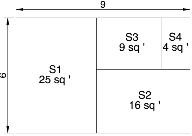
with known areas into a boundary rectangle [10]. Figure 2.2 shows an example of the result
of the treemap algorithm on a rectangle with four interior rectangles with areas of twenty-five,
sixteen, nine, and four square feet. Treemap algorithms are originally from the field of
com-puter visualization and partition rectangles into a number of sub-rectangles that are sized based
on proportions within some data set [10].
Squarified Treemapwas first proposed as an algorithm for functional layout generation in
[11]. Given a target area per room, the rooms are split into functional categories and place
in a Squarified Treemap. Next, a corridor is dynamically located via the interior points and
subtracted from the adjacent rooms with polygon operators. The dynamic corridor placement
algorithm was extended in [1] with an optimization technique based on a shortest path search
that reduced the functional area removed from the layout’s rooms by the corridor. The benefit
of these treemap algorithms is that they do not require a search through a combinatorial space
giving them excellent time to completion. However, due to the dynamic corridor algorithms,
2.2. LiteratureReview 11
Figure 2.2: Example Treemap Representation
room in a residential home must house large furniture that could not fit in a room with a very
narrow dimension even though the desired area for the room may be met by the algorithm with
a room that is long and narrow.
Other approaches have been proposed based on optimization strategies such as simulated
annealing [12], constraint-satisfaction [13], and genetic algorithms [14]. These strategies
pro-pose mutable data structures to represent layouts, iterate through candidate solutions and
mea-sure their quality based on a heuristic cost function. The representations vary from lists of
movable edges [12], enumerated grid spaces [13], and shape grammar expressions [14]. The
fitness functions are based on parameters such as room connectivity, area and aspect ratio.
These algorithms have been shown to generate layouts that resemble those designed by an
ar-chitect from a similar specification with a primary focus on residential styles. The performance
of each algorithm depends on the solution space of the model chosen to represent a layout. For
example, in [12], the solution space of the algorithm is large due to the fact that it includes
any layout that can be formed from shifting walls to new locations but only a small percentage
of this space is explored by the simulated annealing heuristic. This is smaller than the total
algo-rithm requires examination of the entire solution space with backtracking. Algoalgo-rithms that can
find desirable layouts without resorting to a full search of a combinatorial space are desired to
reduce the run-time of the solution and enable generation of multiple candidate solutions.
2.3
Formulating the Layout Generation Problem
As of yet, no author has presented a general language for comparing functional layout
gener-ation algorithms and the sub spaces of solutions they explore. A general representgener-ation of the
algorithm allows implementation in a software system with a good object-oriented design to
provide a framework for developing and testing new algorithms. This section will formulate
the layout generation problem with a general language that is applicable to all of the efforts in literature from the prior section. The terminology established in this section will be used
throughout the chapter to refer to the components of a layout generation algorithm. The
prob-lem is formulated in a general manner, and in later sections, the detailed components of a
con-crete algorithm are presented. The general form of this problem can be extended to buildings
of any size and style such as multistory apartment complexes, hospitals, hotels, and residential
homes. It can also be used to produce new layout generation algorithms. The nomenclature
used to derive the standard form of the layout generation problem is presented in Table 2.1.
2.3.1
The Standard Form
Designing a functional layout requires spatial allocation of multiple rooms within some
prede-fined boundary B. This boundary may be a representation of the exterior walls of the building
or the plot of land on which it is to be constructed. The space of possible layoutsF that can
be formed through some spatial partition ofBcontains many solutions to the functional layout
design problem. A candidate solution to the functional layout generation problem is defined in
2.3.1.
Definition 2.3.1. Any layout L ∈ F that is allocated within a building based on a set of user
specifications U constitutes a candidate solution. A layout L is composed of a set of rooms R.
2.3. Formulating theLayoutGenerationProblem 13
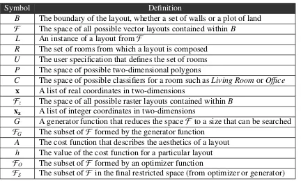
Table 2.1: Functional Layout Generation: Nomenclature for the General Form
Symbol Definition
B The boundary of the layout, whether a set of walls or a plot of land
F The space of all possible vector layouts contained withinB L An instance of a layout fromF
R The set of rooms from which a layout is composed U The user specification that defines the set of rooms P The space of possible two-dimensional polygons
C The space of possible classifiers for a room such asLiving RoomorOffice x A list of real coordinates in two-dimensions
Fz The space of all possible raster layouts contained within B
xz A list of integer coordinates in two-dimensions
G A generator function that reduces the spaceF to a size that can be searched
FG The subset ofF formed by the generator function
A The cost function that describes the aesthetics of a layout h The value of the cost function for a particular layout
FO The subset ofF formed by an optimizer function
FS The subset ofF in the final restricted space (from optimizer or generator)
or all of each r ∈R.
The layout generation problem can thus be phrased as an optimization that seeks the
so-lution L that best matches U from F and requires the placement of R. The best layout is
determined by a heuristic cost function that will be developed in later sections. To place each
of the rooms, a functional classifier and location must be chosen. Creating a candidate
solu-tion to the problem thus requires forming a polygon and deciding upon a classifier for each
of the rooms specified by the user in a manner that satisfies any constraints in the input. This
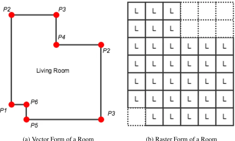
representation will be defined as thevector formof a room and is formally presented in 2.3.2.
Figure 2.3a presents an example of a room that is in vector form.
Definition 2.3.2. The vector representation of a layout is a set of rooms R, where ∀r ∈ R
(r = {p,c} | p ∈ P∧c ∈ C) and p is a two dimensional polygon with a list of coordinates x ∈ R2, P is the set of possible two dimensional polygons, c is a classifier such as ”Living
Room” or ”Office”, and C is the set of possible classifiers.
A layout in which all rooms are in vector form is defined to be the standard form of a
be shown through examples in Section 2.3.2. As an example, consider a representation that
relies on the assumption that the coordinates that form the polygons of the rooms are integer
multiples of some unit rather than real numbers. This means that the coordinatesx=uxzwhere
xz ∈ Z2 and the unituis some parameter chosen by a user. Theuvalue could for example be
taken to be one meter as in [1] as this is the proposed width of the narrowest space in a layout,
the corridor, or it could be taken as some fraction of an inch for the largest unit that can be
practically measured when constructing the layout.
This form will be defined as theraster formof a layout. It can be visualized as a grid based
partition of the boundary in which each block is approximatelyu×uas shown in Figure 2.3b
and defined in 2.3.3
Definition 2.3.3. The raster representation of a layout is a set of rooms R, where∀r ∈ R(r = {Br,c} | Br ⊂ BzVc ∈C)and Br is a set of grid blocks, Bzis the total set of grid blocks from
partitioning the boundary into a grid with unit u, c is a classifier from the set C of possible
classifiers, Br1∪Br2∪...∪Brn= Bz, and Bri∩Br j ={0}, .
To rephrase, the raster form of a room consists of a set of grid blocks that is a subset of all
grid blocks from the boundary of the layout as well as a classifier. The subsets of blocks are
mutually exclusive and union to form the full boundary.
2.3.2
The Solution Space
Additional properties of the solution space must be derived before it is possible to choose an
effective search strategy. The first that will be considered is the size of the solution space. The size ofF is presented in Lemma 2.3.4 which follows from its definition as containing all
possible polygonal partitions ofB.
Lemma 2.3.4. There are uncountably infinite members of the set of possible functional layouts
F in standard form for a building.
Proof. If a specific plot of land represented by a two-dimensional polygon on which a building
is to be constructed is partitioned into a known number of rooms with known classifications,
2.3. Formulating theLayoutGenerationProblem 15
(a) Vector Form of a Room (b) Raster Form of a Room
Figure 2.3: Different Mathematical Representations for a Single Room
of this, where two rooms are left to be placed in the layout. Even in this simple example,
when all but two rooms have been placed, there are infinite locations along the axis of the outer
boundary to place the wall that subdivides them.
The solution space is reduced if the layouts are in raster form. Lemma 2.3.5 shows the
number of possible solutions when the layouts are generated in this form.
Lemma 2.3.5. The number of possible layouts in raster form in the solution spaceFz where
Fz⊂ F formed by partitioning B into n grid blocks is given bykFzk=
nkCk
n
.
Proof. If there arengrid blocks, eachc∈Ccan be assigned a maximum ofntimes. There are
thusnkCkpossible classifiers from whichnmust be chosen. Therefore the number of possible
combinations is given bynknCk.
Asu→ 0,n→ ∞,kFzk → ∞andFz→ F. The set of possible raster layouts thus diverges
to the set of possible vector layouts asubecomes zero. This result shows that the vector form is
a higher level representation that can be employed depending on the assumptions inherent to the
specific layout generation problem. An algorithm that provides a solution in vector form can
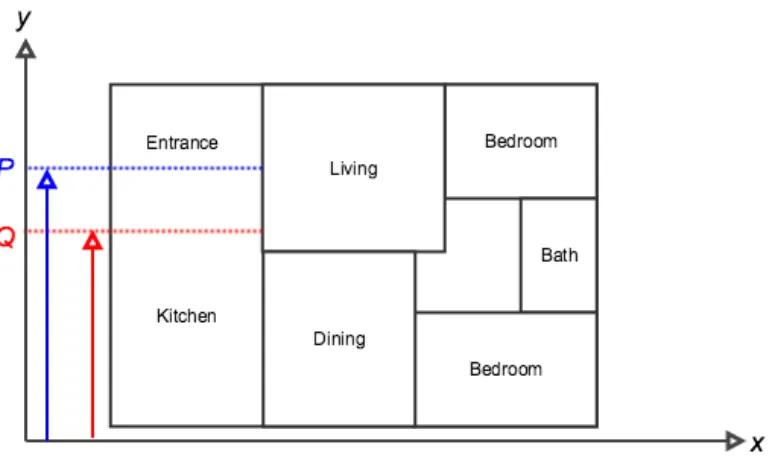
Figure 2.4: Visual example of the result in Lemma 2.3.4. Partitioning the final section into the entrance and kitchen presents uncountably infinite possibilities between y = P andy = Q if y∈ R.
is sacrificed in the process. This is the rationale for defining the vector representation as the
standard form of a layout.
2.3.3
The Generator Function
The size of the solution space in both raster and vector forms is too large for every element to
be examined. In order to solve this problem, the size of the solution space must be reduced in
some manner. This will be accomplished with agenerator functionand is defined in 2.3.6.
Definition 2.3.6. A generator is any function G that restrictsF to a subsetFGof layouts where
G:U → FGandFGis finite.
The generator function can be any algorithm that either partitions a predefined polygonal
boundary for the building or iteratively refines an initial solution fromFGthat is simple to form.
The generator function affects the characteristics of the solutions that can be formed, reducing the vast space of possible room arrangements to a finite amount for a given user input.
The use of the generator function introduces the possibility that the global optimum may
2.3. Formulating theLayoutGenerationProblem 17
acceptable this is unlikely to be a concern for the majority of generator functions. A solution
close to the global optimum or even a good local optimum will likely be an acceptable solution
to the problem depending on the nature of the generator. The commentary presented when a
generator function is proposed should acknowledge this possibility and will only be acceptable
if a logical reasoning can be applied to dismiss the concern. This will be further addressed
during the derivation ofEvolutionary Treemap.
2.3.4
Optimizer Functions
A second class of functions can be used in order to alter the characteristics ofFG by forming a
new solution space with superior resultsFO. Theseoptimizer functionsare defined in 2.3.7
Definition 2.3.7. An optimizer is any function O where O:FG → FO∧ FO ⊂ F.
Optimizer functions are optional components of a layout generation algorithm that can
improve the results such that an architect will require less time tailoring the final result to meet
a specific need. For example, the corridor placement subroutine in [1] can be considered as an
optimizer function. It transforms a layout with rooms that have already been allocated into an
improved layout with greater accessibility between rooms. Optimizer functions can increase
the possibility that the global optimum of the optimization is found. Throughout the chapter,
FS will be used to refer to the final restricted solution space formed through the operation of a
generator function and any number of optimization functions.
2.3.5
The Cost Function
The solutions inFS must be measurable in some manner to quantify their architectural quality
or desirability to a user based on their specification. The heuristic defined in 2.3.8 is a class of
function that maps membersL∈ FS to quantitative values.
Definition 2.3.8. A layout generation cost function is any function A that quantitatively
mea-sures the aesthetics of a candidate solution h where A: (L,U)→h
FormingArequires the definition of parameters that can be computed based on the vector
aesthet-ics. These parameters are highly specific to the generator function that is chosen for searching
through the possible layouts. For example, one generator function may restrictF by omitting
the possibility of forming a layout that contain rooms with very large aspect ratios and thus
the aspect ratio of a room will need not be considered in the cost. Another may omit layouts
that do not fit within a preallocated boundary resulting in a cost function that need not consider
protrusions from the boundary as a parameter.
A layout generation algorithm is thus formed by restrictingF toFS through application of
a generator function and any number of optimizer functions, then finding the global optimum of
AoverFS. The naive layout generation algorithm is thus to simply reduce the space of possible
solutions to a finite set and then find the global optimum of the aesthetic cost function mapped
to the set. Though this may be accomplished through any well known optimization algorithm,
it is likely that, despite a finite number of members,FS may be combinatorial in size. Finding
the optimum value in these large cases can be accomplished with stochastic algorithms such as
simulated annealing and evolutionary algorithms.
2.4
Evolutionary Treemap
The general form of a layout generation algorithm presented in the prior section provides a
useful framework for introducing and comparing methodologies for automated building
gener-ation. This section will use the general form to introduce theEvolutionary Treemapalgorithm.
This algorithm is proposed to automate building interior layout design with respect to an
ar-chitectural specification using genetic optimization meta-heuristics. The optimization searches
through the space defined by a specialized rectangular boundary partitioning algorithm based
on Squarified Treemap[10]. The algorithm scales to moderate numbers of rooms making it
well suited for generation of small office, school, and hotel buildings. For larger numbers of rooms, the algorithm’s runtime must be increased in order to find acceptable solutions. The
algorithm consists of three subroutines that will be introduced in the following sections: the
2.4. EvolutionaryTreemap 19
2.4.1
Rectified Treemap
Evolutionary Treemap is an algorithm that restricts the solution space of possible layouts
with the generator functionRectified Treemap. This algorithm is closely related toSquarified
Treemapin that it partitions a rectangular boundary into a set of sub-rectangles with a recursive
algorithm [10]. The difference between the two algorithms is thatRectified Treemapaccounts for user defined aspect ratios as well as area proportions for the partition’s child rectangles
thereby allowing incorporation of narrow rooms in the partition.
TheRectified Treemapalgorithm is presented in Algorithm 1. It consists of two subroutines
named rectify and maxError. The first subroutine, rectify, is the driver function for placing
rectangles within the initial rectangular boundary and is the same as the function that drives
Squarified Treemappresented in [10]. Therectifyfunction accepts a list of rectanglesrectsthat
have not been placed, which are structures that contain a desired area and aspect ratio for the
room, a list of rectanglesrowwhich have already been placed in the current row and the width
of the current roww. Rectifyplaces the rectangles within the remaining boundary recursively,
finalizing a portion that has been placed based when the maximum error of the aspect ratio of
a rectangle in the row has been increased.
ThemaxErrorsubroutine computes the difference between the desired aspect ratio for each rectangle and the aspect ratio that is expressed with the current placement. This measures
the error in the room shapes with respect to the user specified area and aspect ratio. The
maxErrorfunction is the difference between the rectified andSquarified Treemapalgorithms. The algorithm generates the same output as Squarified Treemap in the special case where all
of the aspect ratios are specified to be one. However, in functional layouts that require narrow
rooms, such as closets, the algorithm allows different results thanSquarified Treemapthat will be closer to the desired values.
TheRectified Treemapgenerator function reduces the overall size of the solution spaceF.
The actual size of the restricted spaceFg is still large, however, and thus it is likely that it will
contain the global maximum or a good local maximum of the cost function. The size of the
space is dependent on the number of rectangles that are placed by the algorithm. The ordering
Algorithm 1Rectified Treemap
1: procedurerectify(listrects,listrow,w)
2: c←head(rects)
3: if maxError(row,w)≥maxError([row,c],w)then
4: rectify(tail(rects),[row,c],w)
5: else
6: finalize(row)
7: rectify(rects,[],width())
8: end if
9: end procedure
10: proceduremaxError(listrects,w)
11: s←sum(rects.areas)
12: m← −∞
13: forr ∈rectsdo
14: ratio←max(w2r.area/s2,s2/w2r.area)
15: error←abs(ratio−r.aspectRatio)
16: if error>mthen
17: m=error
18: end if 19: end for
20: returnm
2.4. EvolutionaryTreemap 21
placement of the rooms along the smallest dimension of the input boundary. Since there are
n! possible orderings of this list, the size of Fg is therefore alson!. This is large enough that
a desirable solution will still be present but small enough that it can be searched effectively. This result will be examined further in Section 2.4.3 when Evolutionary Treemap’s genetic
optimization heuristic is presented.
2.4.2
Corridor Placement
The layouts that result from Rectified Treemap approximate the input specifications from the
user with respect to the aspect ratio and area of each room. The rooms must also be oriented
such that each can be accessed. Theseconnectivityrelationships are not addressed byRectified
Treemap. Generating layouts that meet shape and connectivity requirements requires an
opti-mizer function that places a corridor. This algorithm, one of the components ofEvolutionary
Treemap, maps the solution space from theRectified TreemapalgorithmFgto a new spaceFo
where each of the solutions contains a corridor that connects the rooms.
Corridor finding algorithms based on graph theory form the basis of this work. To produce
corridors in layouts that contain larger variability in the location and number of rooms, an
enhancement based on a spanning tree algorithm is proposed to the graph algorithm presented
in [1]. The base algorithm, as presented in [1], finds the interior edges of the layout and
considers them to be graph. The algorithm then prunes The vertices that have a degree of one
in this graph from the layout. Next, the algorithm subtracts a polygon formed based on the
resultant edges from the layout with polygon operators.
Finding the minimum spanning tree of the corridor graph helps reduce redundant
corri-dor loops in layouts with many rooms. Figure 2.5 introduces the need for the spanning tree
algorithm. In this figure, the corridor graph resulting from the pruning algorithm contains
re-dundant loops between rooms. Including these loops in the corridor contributes to wasted space
in the layout. These loops can be eliminated by finding a spanning tree in the corridor graph.
Typically, the minimum spanning tree is desired as this finds the corridor with the smallest
possible area and excludes the loops. Therefore, to enhance the corridor placement algorithm,
ideal corridor placement.
(a) Initial corridor graph containing all inte-rior edges of the layout
(b) Path after the pruning algorithm from [1] is applied
(c) Path after the spanning tree algorithm is applied
(d) Final layout after corridor graph is clipped from the rooms in the layout
Figure 2.5: In larger layouts, applying the spanning tree algorithm eliminates redundant edges in the corridor to minimize wasted space
Algorithm 2 shows the full procedure that is used in Evolutionary Treemap to place the
rooms in the layout. This function,generateLayout, accepts the boundary of the layout and an
ordered list of structs containing room areas and identities,rooms. It then forms the final layout
by callingRectified Treemapand subtracting a corridor from the resultant set of polygons.
Algorithm 2Generate Layout
1: proceduregenerateLayout(listrooms,boundary)
2: map ←recti f iedT reemap(rooms)
3: layout ← placeCorridor(map)
4: returnlayout
2.4. EvolutionaryTreemap 23
2.4.3
Evolutionary Optimization
The function used to generate layouts presented in Algorithm 2 accepts an ordered list of rooms
and places them within a boundary. The analysis in Section 2.4.1 showed that the number of
possible solutions for a specific list of rooms of sizento theRectified Treemapalgorithm isn!.
Though this solution space is much smaller than infinite, it is still too large in size to be able to
express every possible solution. An evolutionary optimization algorithm is proposed to search
through this large solution space for an optimal layout.
Evolutionary algorithms model the problem data as a chromosome from the field of
bi-ological genetics. The algorithm begins with a population of chromosomes which are then
crossed over to generate offspring, subjects the offspring to mutations, and then integrates the offspring into the population. The evolutionary algorithm considers a chromosome to be a spe-cific ordering of the input room vector represented by random keys. This form of evolutionary
algorithm, that searches through the permutations of a vector to find an optimal value is similar
to solutions that have been proposed to the traveling salesman problem as in [15].
Each random key chromosome corresponds to an input to the generateLayout function.
These chromosomes represent different permutations of the list of rooms. Algorithm 3 converts chromosomes to layouts so that their aesthetic qualities can be measured by the cost function
costValue. The conversion algorithm accepts the list of rooms and their sort order, places them
withRectified Treemap, clips the corridor, and returns the cost value based on the input list of
area values,areas, and aspect ratios,aspect.
Algorithm 3Cost Function
1: procedurecost(listrooms,listsortKeys,listareas,listaspect,)
2: sort(rooms,sortKeys)
3: map ←recti f iedT reemap(rooms)
4: layout ← placeCorridor(map)
5: returncostValue(layout,areas,aspect)
2.4.4
Measuring the Cost Value
The cost function for the algorithm combines a set of parameters corresponding to the user
desired appearance of the layout to compute a value. Since some of the problem’s constraints
are guaranteed to be satisfied inRectified Treemaplayouts, they can be excluded from the cost
value calculation. These are examples such as the rooms being contiguous and rectilinear.
The parameters that are not guaranteed by theRectified Treemapalgorithm are the adjacency
relationships and the shapes of the rooms. This is because of area removal in the corridor
al-gorithm, the heuristic nature of themaxError placement function and the effect of placement order on adjacency relations. These three combine to produce rooms with aspect ratios, areas,
and adjacencies that are not exactly as specified. These parameters highly depend on the
or-dering of the rooms as they are passed to the treemap function. For example, if two rooms are
adjacent in the ordering of the specification, it is highly likely that they will be placed adjacent
to each other in the layout. Additionally, the order of the rooms affects the maxError place-ment heuristic and thus the final size of the rooms. It also affects the location and number of the interior edges, which contribute to the corridor.
The cost value must consider the important values that are excluded from the Rectified
Treemap generator algorithm to produce appealing layouts. It is thus modeled with (2.1),
whereS is the shape cost function, Ris the list of rooms,C is the adjacency cost function, A
is the list of adjacencies present in the layout andc1 andc2 are positive coefficients chosen by the user.
C(R,A)=c1S(R)+c2Aj(A) (2.1)
The shape cost of the layout is calculated by measuring the error between the dimensions of
the actual instantiation of the rooms and the user specified dimensions of the rooms as in (2.2).
In this function, Uarea(r) is the user specified area of room r, Uaspect(r) is the user specified
aspect ratio of roomr, area(r) is the actual area of room r andaspect(r) is the actual aspect
ratio of roomr. If roomr is not a rectangle, the aspect ratio of the convex hull of the polygon
is used. Lower values of this function correspond to a layout where all of the rooms are close
2.5. SystemDesign andImplementation 25
corridor as layouts that have a large corridor will take too much space that could be allocated
in a room.
S(R)= X
r∈R
Uarea(r)−area(r)
Uarea(r)
+ Uaspect(r)−aspect(r)
Uaspect(r)
(2.2)
The adjacency cost, calculated by (2.3) is simply the sum of the weights for each of the
adjacent relationships that is present in the layout. These weights can either be user provided
for a specific layout or as part of a larger database for room identities. Lower values of this
function represent layouts that have more desirable adjacency relationships which are
quanti-fied based on the values of the weights due to the negative multiplier. For each adjacencya∈A
containing two room identities, the weight function returns a positive number specified by the
user that ranks the importance of the adjacency between the two room identities.
Aj(A)=−
X
a∈A
weight(a) (2.3)
The effects of both of these terms in the cost function is highlighted by Figure 2.6. The user specification for the shapes of the rooms in this layout was a single 8’ by 6’ bathroom, three 7’
by 5’ offices and one 10’ by 12’ reception. An adjacency between the reception and bathroom was given a score of 1 and all others a score of 0. The boundary was 27’ by 18’.
When the shape term is excluded from the optimization in Figure 2.6a, the resultant layout
does not contain rooms with appealing shapes based on the input specification as the
bath-room’s final size is much larger than the input. Note that the rooms will all be slightly larger
than the inputs because the specified sizes fill 63% of the boundary. When the adjacency term
is excluded from the optimization in Figure 2.6b, the reception and the bathroom are not
adja-cent. When both terms are included in Figure 2.6c, there is a compromise in the final shapes
and locations of the room that more closely matches the input.
2.5
System Design and Implementation
Evolutionary Treemapwas implemented within QCAD [16], an open-source CAD software,
(a) Optimization with the shape cost removed
(b) Optimization with the adjacency cost removed
(c) Optimization with full cost func-tion
Figure 2.6: Effect of cost function parameters on the generated layout based on the following set of high-level requirements:
• The software must be fast due to the nature of the stochastic optimization algorithms that
are used to compute the location of the rooms in the layout.
• High performance computers must not be required on the client side such that no
spe-cialty hardware is required to run the software.
• The software must be designed to function with existing CAD software and is able to
plot the resultant layouts on the canvas.
• The software should not be specific to one CAD software allowing the possibility to
function with any program through extension interfaces.
• Users should be able to specify the layout with words and numbers in a spreadsheet-like
document rather than drawing the shapes for the rooms themselves.
This section explains the design and implementation of the layout planning software
2.5. SystemDesign andImplementation 27
the object-oriented design of the algorithms library, and the application programming interface
(API) for the web server.
2.5.1
Representation of the User Specification
The first stage of designing this software is to specify the types of inputs that will be required to
describe the desired layout. These were presented to the user as a spreadsheet and represented
in software in JSON format. The first input required by the software is the identity and number
of the rooms that are desired in the layout. For example, a user must be able to specify a three
bedroom house with one living room and kitchen. The meaning of a room’s identity must also
be specified by a user. For example, the living room should be associated with a desired shape
and size. Finally, the relationship between rooms must be enumerated. For example, the living
room and kitchen should be adjacent.
The first item that must be entered by a user is the list of room identities and target shapes.
In this representation, the rooms are assumed to be rectangles and the dimensions given for
each are the length and width. The length and width of the room both quantify the area and the
aspect ratio of the room. This identifies the desired size and shape of the room in the layout.
The second item that must be entered by the user is the desired adjacencies between rooms.
This relationship can be represented by a graph, called a connectivity graph, where each roomr
inRis represented by a vertex and anyriis connected by an edge torjwith somewif the rooms
are desired to be adjacent. Each weight,w, represents a heuristic measure of the desirability of
the connection. They could also be used as identifiers for the type of desired connection, for
example doorways or open walls.
If all inputs are considered as hard constraints in the final layout the problem can be over
constrained. To reduce the possibility that a layout cannot be found for a given user input, the
inputs other than the number of rooms and their identities are treated as soft constraints. The
algorithm attempts to match as many as possible but provides no guarantee that they will all be
met. Due to the heuristic nature of stochastic optimization, a user can run the program multiple
facilities provided by the CAD software. A user can edit a layout that is close to their desired
specifications to create a design that meets all of their requirements and still spend less time
and resources than required by manual efforts.
2.5.2
Software Library Architecture
This component of the software contains the implementation of theEvolutionary Treemap
al-gorithm and contains facilities for extending the work to additional layout generation methods.
The core algorithms library is implemented in Scala, a Java Virtual Machine (JVM) based
lan-guage [17]. This lanlan-guage enables rapid development of algorithms and project components
due to its concise functional programming syntax. The language also is operable with any
library written in Java and benefits from run-time performance enhancement from the JVMs
Just-In-Time (JIT) compiler.
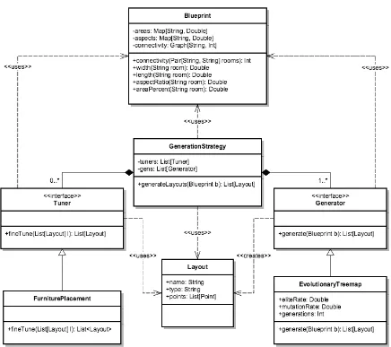
The layout generation system was implemented with the architecture shown in Figure 2.7.
This system contains theGeneration Strategyclass to manage the generation procedure and the
Blueprintclass to encapsulate the parameters requested by a user including desired
connectiv-ity, area and aspect ratio. It also contains the Generator interface to encapsulate algorithms
such as Evolutionary Treemap and the Tuner interface to provide a future facility for
algo-rithms that add features to the layout such as furniture, doors, and windows. To enable higher
levels of the library to enact classes that implement the Generator or Tuner interfaces
with-out details of the actual implementation, the class hierarchies follow the Strategy pattern [18].
This allows storage of classes that implement these interfaces in a single container that can be
iterated over in a polymorphic manner.
Algorithm 4 shows the run method of the Generation Strategy class. This method
ac-complishes the generation of the layouts with two stages. The first transforms the abstract
requirements of the Blueprintinto a concrete set of Layout instances in vector form with the
Generator instances. The second stage of the method passes each vector layout through
mul-tiple stages of fine tuning. Each of these stages updates the individual layout with features that
more closely matches the user specifications. The final result is an array of vector layouts that
2.5. SystemDesign andImplementation 29
Figure 2.7: UML Diagram of the Layout Generation Software
2.5.3
API Design
A web service was developed for the core algorithms library to facilitate communication with
remote clients. This artifact enables client applications to generate layouts by issuing HTTP
commands. The web service was implemented in Scala due to the availability of multiple
modern web frameworks. This simplified the build configuration and compatibility with the
core library. The web service was developed with the Play Framework [19].
The web service is a multi-threaded RESTful application, meaning that no persistent
con-nections are maintained between the service and its clients. Each session is run in a thread pool
Algorithm 4GenerationStrategy
1: proceduregenerateLayouts(blueprint)
2: layouts← List[Layout]()
3: forgen∈gensdo
4: layout← gen.generate(blueprint)
5: layouts.append(layout)
6: end for
7: forlayoutinlayoutsdo
8: fort ∈tunersdo
9: layout= t.f ineT une(layout)
10: end for
11: end for
12: returnlayouts
13: end procedure
a new session is requested, the service launches a new Future and immediately replies to the
client with a unique hash code. Status messages generated by the core library are queued and
sent to the client when requested through a specific route. The client can detect when a solution
is finished by periodically checking the status messages. A completed solution can be retrieved
by an HTTP GET request. This protocol is summarized in Table 2.2.
Table 2.2: Web Service API
HTTP Route Action
POST /session/new Returns a JSON object with an ID for the new session DELETE /session/:id/delete Deletes a session with ID=id
GET /session/:id/status Retrieves the status of the session with ID=id GET /session/:id/solution Retrieves the layouts for session ID=id POST /backwards/new/:kernel Backwards compatibility call for new sessions GET /assets/*file Retrieve static files (such as parameters for the GUI)
The assets route contains a set of static JSON files that contain information about the core
library’s algorithms including the parameters required for each generator and optimizer.
Cur-rently this route only contains files that define a set of configured Generation Strategies that
can be chosen by clients. This simplifies the user interface required to work with the library
2.6. Discussion 31
Table 2.3: Shape Specifications for the Rooms in the Medium Sized Office Layout Room Quantity Length (ft) Width (ft) Area (sq. ft)
Server Room 1 6 6 36
Reception 1 12 10 120
Office 2 10 7 70
Lunch Room 1 13 10 130
Large Office 2 10 10 100
Kitchen 1 10 7 70
Conference Room 2 14 10 140
Bathroom 1 10 9 90
2.6
Discussion
Tests of theEvolutionary Treemapalgorithm as implemented with the architecture described in
the prior section show that it generates open-concept layouts in a multitude of styles. Testing
the algorithm was done with a custom architectural layout generation system programmed in
Scala using the Apache Commons Math Library for genetic optimization [20]. This library
provides a random key genetic algorithm that was tailored for use as the optimization
meta-heuristic in theEvolutionary Treemap implementation. This section will present results from
the algorithm for both residential and office layouts.
2.6.1
O
ffi
ce Buildings
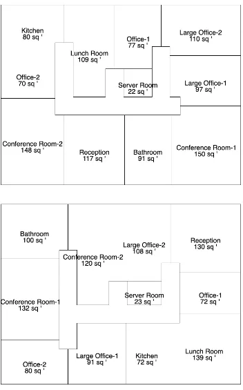
The first style of layout is office buildings. The input specification used to generate the office buildings is shown in Table 2.3. This example is representative of a floor in a medium sized
office building. The algorithm was set to give a weight of 1 for adjacencies from the kitchen to the lunch room, reception to the bathroom, and conference room to the bathroom. The
Evolutionary Treemap algorithm was set to run for 10 generations with a population of 500
layouts. The algorithm requires two other parameters; the mutation rate and the elite rate. The
mutation rate is the degree at which new chromosomes are randomly modified and the elite
rate is the fraction of the chromosomes that are kept from the higher ranks. The mutation rate
of the algorithm was set to 0.08 and the elite rate of the algorithm was set to 0.01. Samples of
the output that is generated by the algorithm is shown in Figure 2.8.
2.6. Discussion 33
For example, in the first layout the kitchen and lunchroom are adjacent and at the end of the
corridor on the top left. The bathroom is also adjacent to one of the conference rooms and
the reception. Though this room is not adjacent to the second conference room, the layout
is a good compromise between the desired features requested by the user. The second layout
is a different style, where the kitchen and lunch room are located in the bottom right corner. The bathroom is now adjacent to both conference rooms and accessible from the hall. In both
examples, the rooms are close to the target sizes as specified.
2.6.2
Open-Concept Residential Buildings
The second style of layouts that shown is residential homes. The input specification used to
generate these layouts is shown in Table 2.4. A weight of 1 was assigned for adjacencies from
the living room to kitchen, kitchen to dining room, living room to dining room, bedroom to
bedroom and bedroom to bathroom. TheEvolutionary Treemapalgorithm was again set to run
for 10 generations with a population of 500 layouts. The mutation rate of the algorithm was
set to 0.08 and the elite rate of the algorithm was set to 0.01. Samples of the output generated
by the algorithm for this specification is shown in Figure 2.9.
Table 2.4: Shape Specifications for the Rooms in the Residential Home Layout
Identity Quantity Length Width Area Percentage Area
Living Room 1 25 20 500 43.86%
Kitchen 1 15 10 150 13.16%
Dining Room 1 12 10 120 10.53%
Bathroom 1 8 6 48 4.21%
Bedroom 3 10 10 100 26.32%
The examples in Figure 2.9 show that the algorithm is suitable for both office and residential styles. As requested, in the first example, the kitchen and living room are adjacent and the
bedroom and bathrooms are accessible through the corridor. The second example has the
kitchen, dining and living room all adjacent and meets more of the connectivity requirements.
This shows that a user can generate multiple examples from the same specification and select