Available online: http://edupediapublications.org/journals/index.php/IJR/ P a g e | 304
Implementation of Handover Based on
X2 Interface in LTE Network
Khin May Yee1,Moh Moh Khaing2,Thu Zar Aung3
1
Faculty of Computer Systems andTechnologies, Computer University, Myitkyina and 1011, Myanmar 2
Information Technology Dept, Technological University, Taunggyi and 06011, Myanmar 3
Information Technology Dept, Government Technological High School, Meiktila and 05181, Myanmar
Abstract
This paper is proposed to implement Handover Based on X2 Interface in LTE Network. Handover procedure in LTE Network has been deeply progressed when competed to the earlier3GPPcriteria. In individual, X2 handover is presented to let neighboring eNBs to hold the user mobility without the contribution of the central network. In this paper, the handover process defines decides the capability of communication networks in keeping the communication link is working. X2 is an interface that must be distributed when the manner of shifting data of time of handover between two eNodeB contiguous sections in LTE. The aptitudes of interface X2 also exploit of the occasion on handover process, so it is required to examine the function of interface X2 when handover occur between eNodeB in LTE. This paper considers the implementation execution of the X2 handover from the UE perspective.
Keyword: handover based X2, RSRP algorithm
1. INTRODUCTION
Mobile data continuous advance appears efficient technologies to satiate the needed quality of service (QoS) of the new services. Mobility is a one of the key structures of current and next generation cellular systems that permits the users to alter flawlessly their point of attachments while using their data and voice services. Handover in Long Term Evolution (LTE), as in previous creation of cellular systems, is a procedure to handover a user equipment (UE) and its context from
a source progressed NodeB (eNB) to a goal eNB. It needs efficient handover decision algorithms in order to improve both UE and network performance and quality. Handover is a “UE-assisted network-controlled” process in that the quantity is described by UE, and the decision is prepared by the
network, i.e. eNBs and/or Mobility
Available online: http://edupediapublications.org/journals/index.php/IJR/ P a g e | 305
MME and are situated in the uniform tracking area (TA). The measurement belongings cover the handover are placed in the same tracking area (TA). The measurement events cover the handover between two cells supplementary the X2 interface between the eNBs.
2. THE LTE HANDOVER PROCEDURE
In LTE, the determination for handovers and the collection of the target eNB are constructed by the assisting eNB established on measurement reports received from the UE. The most common handover picture is
the X2 handover, which occurs in
circumstance the source and target eNBs have an founded X2 relative [6]. From an uplink (UL) and downlink (DL) user plane traffic sending point of view, the handover
can be separated into four stages,
demonstrated in Figure1. In stages 1, principally before the handover, the UL and DL packets are promoted by the source eNB between the UE and the SAE-GW. When the source eNB makes a handover decision for the UE, it negotiates the handover with the target eNB and, if the handover request is accepted, the UE is informed about the target eNB where it should connect to. Phase 2 starts as the UE detaches from the source eNB and attaches to the target eNB. In this phase, the DL packets sent by the server are still forwarded to the source eNB by the SAE-GW, whereas UL packets sent by the UE (after successful radio attach to the target eNB) are delivered through the target eNB to the SAE-GW and finally to the server. Therefore, UL data will not pass through the source eNB any longer. During this phase, the source eNB forwards the DL packets to the target eNB via the X2
Available online: http://edupediapublications.org/journals/index.php/IJR/ P a g e | 306
deduced by the server, i.e.,the two communicating devices are harmonized.
Figure1. Typical LTE X2 handover procedure.
2.1 X2 Application Protocol
Handover style, utilization and completion has entirely altered compared to the inheritance 3GPP technologies. Universal
Mobile Telecommunications System
(UMTS) technology maintained the Radio
Network Controller (RNC),a network
component that was in burden of hold any handover signaling capability. In LTE Evolved Packet System (EPS), RNC has been eliminated and the intelligence is maintained in the eNB side that is accountable for handover. A connection has to be recognized among eNBs in order to signal with each others for handovering. This is achieved through X2 interface, using X2 Application Protocol (X2-AP). X2 interface can be established between one eNB and its neighbors in directive to
conversation the planned information.
Hence, fully mesh topology is not assigned conflicting to S1 interface where a star topology is operated. Moreover, the protocol structure over X2 interface comprises both the control and the data plane protocol stack that is the identical as over the S1 interface as illustrated in Figure2. The X2 topology as
well as the X2- AP structure deliver benefits associated to the data forwarding operation as will be conversed later. In case X2 interface is not organized or the connection is congested; handover can be accomplished
via MME using S1 interface. The
initialization of X2 interface leads with the
neighbor discovery, i.e., based on
configuration or Automatic Neighbor
Relation Function (ANRF) procedure. Then, the Transport Network Layer (TNL) is arranged using the TNL address of the neighbor. Once the TNL is recognized, the X2 format procedure is prepared to run to exchange application level data desirable for two eNBs in order to run correctly via X2 interface. Precisely, the source eNB (i.e., the starting eNB in which the UE is attached) sends the X2 Setup Request to the target eNodeB (i.e., the candidate eNB in which the UE intends to handover). The target eNB responses with the X2 Setup Response. The X2 handover key characteristics are [7]:
The entire procedure is immediately worked between the two eNBs.
MME is complicated only after the handover procedure is accomplished for the path switch procedure dissimilar to the S1 handover that is MME aided reducing the delay and the network signaling above.
The announcement of source eNB
Available online: http://edupediapublications.org/journals/index.php/IJR/ P a g e | 307
Figure2. eNB X2 protocol stack for control-plane and data-control-plane
2.2 Handover Criteria
The RSRP magnitude specifies cell-specific signal strength metric. This measurement is used mainly to rank different LTE applicant cells according to their signal strength and is used as an input
for handover and cell reselection
evaluations. RSRP is well-defined for a specific cell as the linear average expected power (in Watts) of the signals that carry cell-specific Reference Signals (RS) within the considered measurement frequency bandwidth.
In principle the LTE network setup considers for the deployment of eNBs in hexagonal topology. Let B denote the number of deployed eNBs and let [k] denote the ReferenceSignal Received Power (RSRP) from each base station (BS)i ∈ I = {1, . . . , B} at time k 2 in dBm scale. Averaging is performed by an Exponential Moving Average (EMA) filter, i.e., low-pass filter, for smoothing any RSRP abrupt variations
and is applied in the radio resource control (RRC) layer [8](i.e., L3 filtering). High frequency fluctuations are filtered outand can be neglected. The filtered signal is expressed in dBmas follows:
Where∞ ≜ 2−q/4 and q ∈F 3. Handover is
performed using aset of handover
parameters. Here, we refer to their definitions as well as the fields they belong to in the corresponding RRC layer structures, i.e., Report Config EUTRA, Meas Object EUTRA, Quantity Config EUTRA, see also [8]. Specifically, the parameters that could be adjusted are:
Time to trigger (ttt): Time during which specific criteria for the event needs to be met in order to triggera measurement report (time-to-trigger
as defined in Report
ConfigEUTRA).
Hysteresis (hys): the hysteresis parameter for this event (i.e., hysteresis as defined in Report ConfigEUTRA).
OFN (ofn): the frequency specific offset of the neighbor cell frequency (i.e., offset Freq as defined in Meas Object EUTRA).
OCN (ocn): the cell specific offset of the neighbor cell (i.e., cell Individual
Offset corresponding to the
frequency of the neighbor cell as defined in Meas Ob-ject EUTRA).
OFS (ofs): the frequency specific offset of the serving cell frequency (i.e., offset Freq as defined in Meas Ob-ject EUTRA).
OCS (ocs): the cell specific offset of the serving cell(i.e., cell Individual Offset conforming to the serving frequency as well-defined in Meas Object EUTRA).
Available online: http://edupediapublications.org/journals/index.php/IJR/ P a g e | 308
L3 Clarifying factor
RSRP/Reference Signal Received Quality (RSRQ) (q): Parameter for the EMA filter as explained in Eq. (1) (i.e., this parameter is defined within Quantity Config EUTRA). A famous handover principle, commonly
used in conventional HO decision
algorithms for mobile communication
systems (also applied in 3GPP LTE), is established on RSRP s comparison method in which hysteresis and handover offsets are involved. Definitely, in this paper, A3 event is emphasized on and its condition that is used as a criterion for the cell selection.
The criterion is stated as follows:
where s € I and means the serving cell, n € I − s and denotes the neighbor cells. Finally, the handover parameters that are included in Eq. (2) are outlined as labeled above.
The above inequality is translated as follows: when the RSRP of a neighbor cell (sum of the neighbor’s RSRP and offsets, [k] + ofn + ocn) develops greater than that of the RSRP of the serving cell (sum of signal strength and offset, , [k] + ofn
+ ocs) and the alteration is greater than the value of off (referred also as a3-offset), Event A3 is triggered and the UE reports the measurement results to the eNB. Hysteresis (hys) specifies the value of a handover boundary between the source and the target cell. Conclusively, the in equality can be compacted as:
where S = ofn + ocn − ofs − ocs − hys − off. The S can be concluded as a sum of the offsets including all the offset influences in triggering the handover situation.
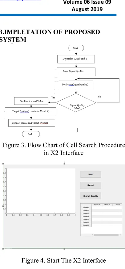
3.IMPLETATION OF PROPOSED SYSTEM
Figure 3. Flow Chart of Cell Search Procedure in X2 Interface
Figure 4. Start The X2 Interface
If this program is run, start the X2 Interface can be shown in the Figure 4.
Available online: http://edupediapublications.org/journals/index.php/IJR/ P a g e | 309
When clicking the plot button, the position of EnodeBs appear. From this EnodeBs, the position two EnodeBs with maximum signal quality will display in Figure 5.
Figure 6. Signal Quality of Maximum and Minimum
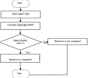
When starting the system, firstly the input signal value must be set. The input signal is calculated by RSRP. After the calculation, the result of signal quality value is get. If the signal quality value is greater than zero, handover is completed. If the signal quality value is not greater than zero, handover is not completed.
Figure 7. Flow Diagram of Handover based on X2 Interface
Figure 8. shows the parameter calculation. It can be assumed that maximum signal quality is 3 and mini signal quality is 5. The power is ignored. If the result is greater than zero, the handover is completed message box is displayed. This is shown in Figure 9.
Figure 8. Input the Maximum Signal Quality and Minimum Signal Quality
Figure 9. Handover completed message box
After Handover, UE is attached to the target eNodeB. If the target eNodeB’s signal quality >0, handover is completed.
Available online: http://edupediapublications.org/journals/index.php/IJR/ P a g e | 310
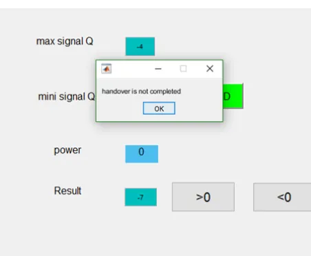
-3. The power is ignored. If the result is greater than zero, the handover is not completed message box is displayed. This is shown in Figure 13.
Figure 12.Input the Maximum Signal Quality and Minimum Signal Quality
Figure 13. Handover not completed message box
If the target eNodeB signal quality <0, handover is not completed.
4. CONCLUSIONS
The new X2 interface offers ways for
distribution information between
neighboring eNodeBs to develop handover and to reduce related intervention. The X2 brings both control plane signaling and progressed user plane data, and the latter decrees the band width necessity. Vendor opinions vary, but most study that 5% of the S1 bandwidth is a large grant for the X2. The S1 bandwidth itself depends on the
operating bandwidth and MIMO
arrangement of the eNodeB it operates. Further studies have shown a typical 10MHz 2x2 downlink which requires a total of around 30-40 Mbps of backhaul per tri-cell eNodeB during busy times. This figure includes S1, X2 and transport protocol overheads.
When the user uses data, the X2 adds delay to the overall budget, and so low latencies are highly desirable. In the future, LTE-Advanced includes a capacity-enhancing technique called Co-ordinate Multipoint Transmission and Reception. It has been shown that even relatively small latencies of 5ms can reduce the gains of such schemes significantly.
Neighboring eNodeBs are nearly covered by the same multipoint sector, which enables rapid turnaround of the X2 traffic. PMP networks form a hub-and-spoke topology, which is much better suited to X2’s peer-peer connectivity than the tree topologies formed by PTP networks.
5.ACKNOWLEDGEMENT
Available online: http://edupediapublications.org/journals/index.php/IJR/ P a g e | 311
6. REFERENCES
[1] S. Oh, B. Ryu, and Y. Shin, “Epc
signaling load impact over s1 and
x2Handover on lte-advanced system,” in
2013 Third World Congress onInformation and Communication Technologies (WICT), Dec 2013, pp.183–188.
[2] S. Oh, H. Kim, B. Ryu, and N. Park, “Inbound mobility management on lte-advanced femtocell topology using x2 interface,” in 2011 Proceed-ings of 20th International Conference on Computer
Communicationsand Networks (ICCCN),
July 2011, pp. 1–5.
[3] E. A. Ibrahim, M. R. M. Rizk, and E. F. Badran, “Study of lte-r x2handover based on a3 event algorithm using matlab,” in 2015 Inter-
national Conference on Information and Communication TechnologyConvergence (ICTC),, Oct 2015, pp. 1155–1159.
[4] N. Baldo, M. Requena-Esteso, M.
Miozzo, and R. Kwan, “An opensource model for the simulation of lte handover scenarios and algorithms in ns-3,” in
Proceedings of the 16th ACM
InternationalConference on Modeling,
Analysis and Simulation of Wireless and
Mobile Systems. New York, NY, USA:
ACM, 2013, pp. 289–298.
[5] 3GPP. 3rd Generation Partnership Project; Evolved Universal Terrestrial Radio; X2 Application Protocol (X2AP)
specification (Release 10); Technical
Specification TS 36.321 v10.7.0.[Online]. Available: http://www.3gpp.org
[6] 3GPP, “Evolved Universal
Terrestrial Radio Access (E-UTRA)
andEvolved Universal Terrestrial Radio
Access Network (E-UTRAN);
Overalldescription; Stage 2,” 3GPP, TS 36.300, Mar. 2014.
[7] S. Sesia, I. Toufik, and M. Baker,
LTE, The UMTS Long Term Evolution:
[8] 3GPP. 3rd Generation Partnership
Project; Technical SpecificationGroup
Radio Acess Network; Radio Resource
Control (RRC); Protocolspecification