Research on Spaceborne SAR HRWS-GMTI Imaging Method Based
on Relax Algorithm
Jin-Meng Wang*, Xu-Dong Wang, Shi-Yu Meng, and Jun-Jie Ma
Abstract—High resolution wide swath (HRWS) imaging and ground moving target indication (GMTI) are similar in terms of system architecture and are based on a multi-channel system in the azimuth direction. However, in order to achieve their respective performance requirements, the HRWS SAR requires a lower pulse repetition frequency (PRF), and the GMTI system requires a relatively higher PRF. In consideration of this contradiction, parameters of the moving target are introduced into the reconstructed filtering vector constructed by each signal reconstruction algorithm, so that the HRWS imaging of the moving target can be realized. In this paper, considering the characteristics of the Relax algorithm, a motion-adapted signal reconstruction algorithm is proposed, and the iterative process of the new method is described in detail. This method can perform GMTI on moving targets with a lower PRF without changing the PRF of the HRWS SAR system. By the simulation of point target echo and comparing with the traditional signal reconstruction algorithms, the reliability and effectiveness of the new method are verified.
1. INTRODUCTION
Because of its all-weather and all-day working characteristics, spaceborne synthetic aperture radar (SAR) can be used as the main means to obtain ground information and has important application value in environmental monitoring, disaster management, wide area monitoring, and maritime traffic monitoring [1]. After decades, along with the development [2], SAR imaging algorithm has been quite mature in terms of robustness, accuracy, practicality, and efficiency [3].
In the future, the main development direction of spaceborne SAR is to image the area of the earth with high resolution and wide swath. High resolution and wide swath are the two most important indices used to measure the imaging algorithm of spaceborne SAR. Wide swath can enable radar to monitor and detect a wide range of areas, avoiding repeated visits to areas of interest; high resolution can enable radar to distinguish the characteristics of the target with high accuracy [4]. However, in the traditional single channel SAR system, the challenge is that due to the limitation of “the minimum antenna area” [5], the requirements of high resolution and wide swath for system design and configuration are different, so they cannot be realized at the same time [6]. On the one hand, in order to achieve high resolution in the azimuth direction, PRF needs to be set very high; on the other hand, in order to avoid ambiguity in the range direction when imaging wide areas, PRF needs to be set low. If PRF is too low for azimuth direction at this time, it will generate ambiguity in the azimuth direction [7]. Therefore, the traditional single channel SAR system cannot meet the growing demand for higher spatial resolution and wider area coverage.
In order to overcome the inherent limitations of single channel SAR system, multiple receiving (RX) channels [8] in the azimuth direction can be adopted, and each channel receives signals independently.
Received 2 November 2019, Accepted 2 January 2020, Scheduled 17 January 2020 * Corresponding author: Jin-Meng Wang (wjm [email protected]).
Through the application of multiple RX channels and digital beamforming (DBF) technology [9, 10], the aliased doppler spectrum of subsampling signals can be reconstructed [11], so as to suppress the ambiguity and achieve an HRWS imaging. GMTI algorithm aims to detect moving targets and accurately estimate their actual position, velocity, and direction of motion [12]. HRWS imaging and GMTI detection are based on an azimuth multi-channel system, so they are related in system architecture. However, in order to achieve their respective performance requirements, HRWS SAR system and GMTI system have different requirements for PRF. In HRWS SAR system, low PRF is needed to avoid the generation of ambiguity in the range direction. The most ideal PRF can make the whole RX antenna array achieves uniform sampling [13]. At this time, the PRF [14] is as follows:
PRFHRWS =
2va
M·L, (1)
In Eq. (1),vais the moving speed of the radar platform, M the number of Rx channels, andL the
length of a single RX channel, which can also be defined as the minimum baseline length that can be achieved along the route.
In a GMTI system, PRF is usually very high, and in order to ensure ambiguity suppression, optimal PRF settings need to meet DPCA (Displaced Phase Center Antenna) conditions [15]. The PRF at this time can be expressed as:
PRFDPCA=
2va
L =M ·PRFHRWS, (2)
The setting of high PRF in GMTI can also ensure that each independent RX channel can be properly sampled and minimize the energy of aliasing signal caused by Doppler shift of moving targets. The setting of multiple RX channels is used to achieve clutter suppression and parameter estimation of moving target [16]. When satisfying the DPCA condition, clutter suppression can be realized in theory. In the process of data registration, the interpolation calculation is not required, and only the data of each RX channel need to be shifted up several sampling points in azimuth [17]. This will lead to that HRWS imaging and GMTI cannot be achieved at the same time. From the principle of realizing the two, as long as PRF is increased to M times in HRWS SAR system, it can be used to realize GMTI. However, too high PRF can realize neither wide-swath GMTI nor wide-swath SAR imaging. Therefore, due to the limitation of PRF, only narrow-swath GMTI or HRWS SAR imaging can be achieved, but they cannot be achieved at the same time. In order to realize moving target detection in HRWS SAR system, the parameters of moving targets can be taken into account when reconstructing filter vectors with signal reconstruction algorithms, so HRWS imaging of moving target can be realized. This method can detect the moving target with lower PRF without changing PRF of HRWS SAR system.
2. THE MOVING TARGET ADAPTIVE HRWS ALGORITHM
The signal reconstruction algorithms commonly used in traditional HRWS SAR systems are not suitable for moving target detection, but for stationary targets without ambiguous Doppler spectrum reconstruction and azimuth ambiguity suppression. The radial velocity of moving target will cause Doppler frequency shift, and the imaging position of moving target will shift in azimuth direction. The function of HRWS signal reconstruction algorithm is to process the ambiguous signal in azimuth direction. So as long as the Doppler frequency shift caused by the radial velocity of moving target is compensated in the reconstruction algorithm, it can be used to correct the Doppler frequency shift caused by the radial velocity of the moving target. Thus the signal reconstruction of the moving target can be realized. The tangential velocity of the moving target mainly affects the focusing effect of the target, so it has little to do with the reconstruction algorithm and can be ignored. In this section, for simplicity, the reconstructed filter vector which considers the doppler shift in Relax method is derived, and the results of signal reconstruction are simulated and analyzed.
2.1. The Motion-Adapted Signal Model
It can be seen from the literature that after transforming to Range-Doppler domain and being reconstructed, the echo signal of stationary point target can be expressed as
Zrec,b
r, fd,b˜
=γbH
fd,b˜
Among them, b = 1,2,· · ·, M denotes the unambiguous Doppler frequency band; r denotes the distance between radar and target; γb denotes the reconstructed filtering vector ofM×1 dimension;Z
denotes the multichannel original echo signal of M×1 dimension; (·)H denotes the complex conjugate
transposition operation;−PRF/2≤fd<PRF/2 denotes the ambiguous Doppler frequency;fd,b˜ denotes
the unambiguous doppler frequency corresponding to the Doppler frequency bandband can be expressed as:
fd,b˜ =fd+
2b−M−1
2 ∗PRF, (4)
It should be noted that Equation (4) is valid only ifM is an odd number. According to the known relationship among doppler frequency, direction cosineut, radial velocity of moving target vr0, velocity
of radar platform va, and wavelength λ, the unobscured Doppler frequency fd,b˜ can also be expressed
as:
fd,b˜ =
2va λ ut−
2vr0
λ , (5)
At this time, Equation (3) can be rewritten as follows:
Zrec,b
r, fd,b˜
=γbH(ut, vr0)Z(r, fd), (6)
This equation is a reconstruction formula suitable for the signal reconstruction of the moving target. The reconstructed filter vectors in the signal reconstruction algorithm also need to be modified according to the parameters of the moving target, so the adaptive reconstructed filter vectors of the moving target can be expressed as:
γb(ut, vr0) =
1
Gb(ut, vr0) ·A
(u(ut, vr0, ϑ))× ∅(ut, vr0)·1M, (7)
Among them, Gb denotes the normalization factor of the antenna pattern; A denotes the M×1
dimensional antenna pattern matrix; 1M denotes the M ×1 dimensional unit matrix; u(·) denotes LOS vector between antenna face and scatter; andϑdenotes the target parameter vector including the parameters of distance and incidence angle. The most important step in signal reconstruction is to determine the baseline delay matrix, which can be expressed as:
∅(ut, vr0) =
⎡ ⎢ ⎢ ⎢ ⎢ ⎢ ⎣ exp
−j2π λx1ut
0 0
0 . .. 0
0 0 exp
−j2π λxMut
⎤ ⎥ ⎥ ⎥ ⎥ ⎥ ⎦ (8)
In Eq. (8), xi represents the distance between RX channel i and RX antenna center, that is, the
distance between RX channeliand TX channel (default the first antenna as the transmit antenna). The matrix in Equation (8) is similar to that used in STAP (Space-Time Adaptive Processing) algorithm. It should be noted that the directional cosine ut in the matrix is a function of unobscured Doppler
frequency and radial velocity, namely ut=ut(fd,b˜ , vr0).
By adding parameters ut and vr0 of the moving targets to the above formula, the signal
reconstruction can also be realized when the moving target echo signal is sampled with the same low PRF as the stationary target. In the following deduction process, it is assumed thatvr0 is a constant in
the observation time determined by the beam width of TX/RX antenna. In a spaceborne SAR system, the beamwidth of antenna is usually less than 1◦. Under this assumption, according to Equation (5), the direction cosine is
ut
fd,b˜ , vr0
= λfd,b˜ 2va
+vr0
va ,
(9)
Compared with Equation (4), the reconstructed unobscured Doppler frequencyfd,b˜ can be expressed
as:
fd,b˜ =fd+
round
− 2vr0 λ·PRF
+2b−M−1 2
round(·) function represents the rounding integer operation, which can ensure the correct reconstruction of the signal and retain the energy of the Doppler frequency moving target signal to the greatest extent.
The signal reconstruction principle of the three-channel system is shown in Figure 1, where PRFHRWS is the sampling frequency when the Anti-DPCA condition is satisfied. According to the
selected reconstructed filter vector γb, HRWS signal reconstruction of conventional stationary targets
(i.e., vr0 = 0) or adaptive signal reconstruction of moving targets can be carried out. After signal
reconstruction, conventional SAR imaging processing or moving target adaptive SAR imaging processing is performed, usually including range migration correction (RCMC) and azimuth compression.
PRF
PRF PRF PRF
3 PRF
Traditional single channel SAR processing or GMTI processing
Range in time domain
Doppler domain
Range in time domain
Doppler domain Signal reconstruction for
each frequency band The signal of three-channel system in range-doppler domain z(r, f a)
HRWS
HRWS HRWS HRWS
HRWS
.
γ (f )
1 a,~1 γ 2(f a,~2) γ 3(f ~a,3)
Z rec,1(r, f a,~1) Z rec,3(r, f a,~3)
Z rec,2(r, f a,~2)
Figure 1. The signal reconstruction principle of channel system.
In practical application, the radial velocity of moving target is usually unknown, so the adaptive signal reconstruction algorithm of moving target can be iterated continuously according to different assumptions of radial velocity, and the range migration correction and azimuth compression of moving target matching are processed with search speed. When the amplitude of moving target reaches the maximum, the estimated radial velocity can be obtained. As long as the step size of speed search is set small enough in the iteration process, there will be no significant performance loss.
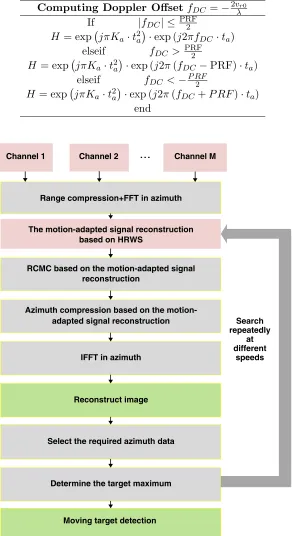
It is worth mentioning that in azimuth compression processing of moving target matching, different azimuth matching functions are needed according to the size of Doppler offset fDC. When |fDC|=| −2vr0/λ| ≤ PRF/2 is used, the traditional azimuth matching function of moving target can
be used; when |fDC| = | −2vr0/λ| > PRF/2 is used, folding will occur. If the traditional azimuth
Table 1. Azimuth compression processing for moving target matching.
Computing Doppler OffsetfDC =−2vλr0
If |fDC| ≤ PRF2
H = expjπKa·t2a
·exp (j2πfDC ·ta)
elseif fDC > PRF2 H= expjπKa·t2a
·exp (j2π(fDC−PRF)·ta)
elseif fDC <−P RF2 H= expjπKa·t2a
·exp (j2π(fDC+P RF)·ta)
end
...
Channel 1 Channel 2 Channel M
Range compression+FFT in azimuth
The motion-adapted signal reconstruction based on HRWS
RCMC based on the motion-adapted signal reconstruction
Azimuth compression based on the motion-adapted signal reconstruction
IFFT in azimuth
Reconstruct image
Select the required azimuth data
Determine the target maximum
Moving target detection
Search repeatedly
at different
speeds
Figure 2. The flowchart of moving target imaging processing for azimuth multichannel spaceborne SAR system.
specific process can be described with the help of pseudo-code, as shown in Table 1. Ka denotes the
Doppler frequency modulation; ta denotes the azimuth fast time; H denotes the azimuth time domain
The processing flowchart of moving target imaging for azimuth multi-channel spaceborne SAR system is shown in Figure 2.
2.2. The Ambiguity Suppression Based on Relax Algorithm
Relax algorithm [18, 19] estimates the parameters of target signal according to the nonlinear minimum variance criterion. It can be used to distinguish multiple targets and has strong adaptability, so it can be used to separate different ambiguous components. From the previous analysis, it can be seen that after the echo of azimuth multi-channel spaceborne SAR system is transformed into Range-Doppler domain, and the data of each Range-Doppler unit are composed of ambiguity and non-ambiguity. If the signal can be successfully separated according to different ambiguity multiples, the ambiguity suppression can be achieved. Based on this idea, this section uses Relax algorithm to suppress the ambiguity. According to the one-to-one correspondence between azimuth frequency and azimuth degree, the orientation vectors corresponding to azimuth frequency under different ambiguity multiples are known, so when using Relax algorithm to suppress ambiguity, only the signal amplitude under different ambiguity multiples needs to be estimated.
The ambiguity suppression method based on Relax algorithm performs traversal for each Range-Doppler unit in the Range-Range-Doppler domain with two nested loops. One cycle traverses all Range-Doppler units, and one cycle traverses all range units. The nesting order of the two cycles can be chosen arbitrarily. The algorithm can be implemented in three steps: initialization, azimuth ambiguity suppression, and azimuth compression. In the following description of the algorithm, P denotes the total ambiguity multiple of the signal. The total ambiguity multipleP needs to be less than or equal to the number of channels M. Here, P is assumed to be an odd number, and p denotes the pth ambiguity. The specific steps are as follows:
Step 1: Initialization. By matching the steering vectors under different ambiguous multiples with the original signal, the ambiguous signal and non-ambiguous signal are preliminarily distinguished, and the preliminary estimation of the amplitude of the signal under different ambiguous multiples is obtained. According to the one-to-one correspondence between azimuth frequency and azimuth degree, the steering vectors ap(fd) with different ambiguous multiples are constructed (ap(fd) is the reconstruction vector γb):
ap(fd) =
exp
−j2π(fd+pfp)d1 va
... exp
−j2π(fd+pfp)dM va
T
, (11)
After completing the matching operation:
Zrec1(r, fd+pfp) =
aHp (fd)∗Z(r, fd)∗d1
M , (12)
In Eq. (12),Zrec1(r, fd+pfp) represents the magnitude of the preliminary estimatedpth ambiguous
component.
Step 2: Azimuth ambiguity suppression. According to the original signal and preliminary estimated signal amplitude under different ambiguous multiples in Step 1, the signal vectors corresponding to different ambiguous multiples can be obtained. Then, the steering vectors under different ambiguous multiples are matched with the corresponding signal vectors respectively, that is to say, the following two iteration steps are completed in turn:
First iteration:
Zp1(r, fd) =Z(r, fd)−
(P−1) 2
i=−(P−21), i=p
ai(fd)∗Zrec1(r, fd+pfp), (13)
ˆ
Zrec1(r, fd+pfp) =
aHp (fd)Zp1(r, fd)
M , (14)
In Eqs. (13) and (14),Zp1(r, fd) denotes thepth ambiguous vector obtained in the first iteration,
and ˆZrec1(r, fd+pfp) denotes the magnitude of the pth ambiguous component estimated in the first
kth iteration (k≥2):
Zp k(r, fd) =Z(r, fd)−
(P−1) 2
i=−(P−21), i=p
ai(fd)∗Zˆrec k−1(r, fd+pfp), (15)
ˆ
Zrec k(r, fd+pfp) =
aHp (fd)Zp k(r, fd)
M , (16)
In Eqs. (14) and (16),Zp k(r, fd) denotes the kth ambiguous vector obtained in thepth iteration;
ˆ
Zrec k−1(r, fd+pfp) denotes the amplitude of thepth ambiguous component estimated in the (k−1)th
iteration; ˆZrec k(r, fd+pfp) denotes the amplitude of the pth ambiguous component estimated in the kth iteration.
Iterate iteratively until convergence, or the number of iterations is reached. The formulas for testing convergence are as follows:
F =
Z(r, fd)−ap(fd) ˆZrec(r, fd+pfp)
H
Z(r, fd)−ap(fd) ˆZrec(r, fd+pfp)
. (17)
when the relative change of the cost function F is less than or equal to 0.001, the iteration should be terminated.
Step 3: Azimuth compression. The signal after ambiguous suppression is arranged in order of ambiguous multiple, then the azimuth matching compression processing is carried out to complete the SAR imaging processing, and the image result after ambiguous suppression is obtained.
3. SIMULATION AND RESULT ANALYSIS
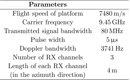
Firstly, the position of the concave in the angle (direction cosine)/Doppler plane of the traditional signal reconstruction algorithm and the moving target adaptive signal reconstruction algorithm is analyzed. Then, the moving target signal is reconstructed by the traditional signal reconstruction algorithm and the moving target adaptive signal reconstruction algorithm, respectively, and the reconstructed results are also simulated. In order to observe the final imaging effect, a moving target with a radial velocity of 9 m/s is set; Gauss noise is added to the echo; and the SNR is 12 dB. The system parameters used in the simulation process are shown in Table 2. The PRF values satisfy the Anti-DPCA conditions.
Table 2. Parameter setting of multichannel spaceborne SAR system.
Parameters
Flight speed of platform 7480 m/s Carrier frequency 9.45 GHz Transmitted signal bandwidth 80 MHz
Pulse width 5µs
Doppler bandwidth 3741 Hz Number of RX channels 3 Length of each RX channel
(in the azimuth direction) 4 m
3.1. Analysis of Concave Position in Angle (Direction Cosine)/Doppler Plane
2
PRF
2
PRF
2
PRF
2
PRF
(a) (b)
Traditional signal reconstruction algorithm
The motion-adapted signal reconstruction algorithm Direction cosine
u t = cos θDOA
Direction cosine
u t = cos θDOA
Doppler shift
Doppler frequency
fDC
fDC
fa fa
Doppler shift
Doppler frequency
-
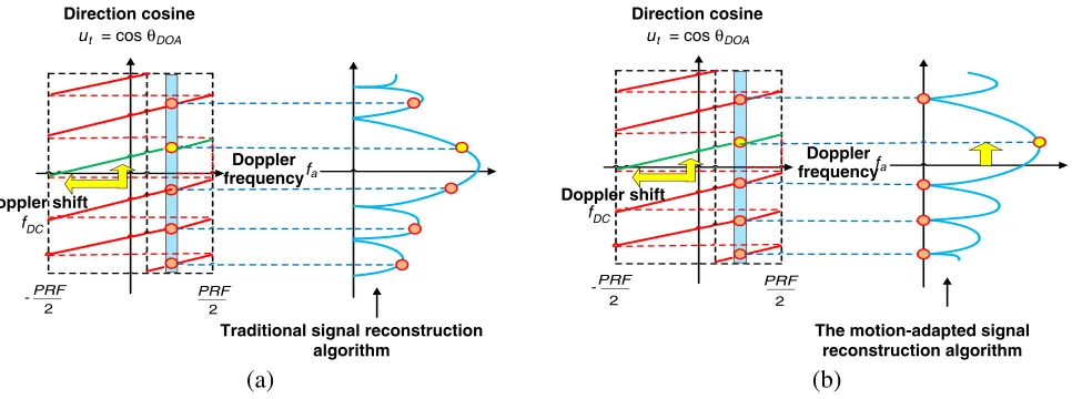
-Figure 3. The position of the concave in the angle (direction cosine)/Doppler plane. (a) The application of traditional signal reconstruction algorithms to moving target signals; (b) The application of motion-adapted signal reconstruction algorithms to moving target signals.
realizing ambiguity suppression. The position of the concave formed by the two algorithms is shown in Figure 3. Figure 3(a) is a result of reconstructing the moving target signal with the traditional signal reconstruction algorithm, and the moving target signal will produce Doppler frequency shift, so the position of the concave cannot correspond to the blurred signal, thus it cannot effectively suppress the blurred signal. As shown in Figure(b), in order to reconstruct the moving target signal by using the adaptive signal reconstruction algorithm, the signal reconstruction algorithm can compensate the Doppler frequency shift caused by the radial velocity of the moving target, so the blurred signal can be effectively suppressed, and the moving target signal can be correctly reconstructed.
3.2. Simulations and Analysis of the Motion-Adapted Signal Reconstruction
Figure 4 is the moving target echo signal when PRF satisfies the Anti-DPCA condition. Figure 4(a) shows that the data reconstructed from the echo signal directly is badly blurred in azimuth direction.
(a) (b) (c)
Compared with Figures 4(a) and (b), it can be seen that the traditional signal reconstruction algorithm cannot suppress the azimuth ambiguity of the moving target signal, but the effect of the azimuth ambiguity suppression which compensates doppler shift in the adaptive signal reconstruction algorithm is obvious.
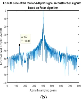
Next, the azimuth compression of the echo data before and after suppressing the ambiguity is carried out, and the results are as follows. Figures 5(a) and (b) are the imaging results before suppressing the ambiguity respectively. It can be seen that there are many ambiguous point targets in the azimuth direction. Figure 6 shows the 3D display and the azimuth slice of the imaging results after suppressing the ambiguity by Relax algorithm. Compared with Figure 5, the results show that only the motion-adapted signal reconstruction of moving targets is achieved. The algorithm can effectively suppress the ambiguous signal and get the real point target, while the traditional signal reconstruction algorithm still has ambiguity after reconstructing the moving target signal. After the moving target signal is suppressed by the motion-adapted signal reconstruction algorithm based on Relax algorithm and normalized, the amplitude of the false ambiguous target can be suppressed below−42.98 dB.
(a) (b)
Figure 5. (a) The 3D display of the original echo signal before suppressing the ambiguity; (b) The azimuth slice of the original echo signal before suppressing the ambiguity.
The simulation results show that the motion-adapted signal reconstruction algorithm based on Relax algorithm can effectively suppress the azimuth ambiguity and reconstruct the moving target signal. In the process of range migration correction, the signal can be corrected according to the searched radial velocity, and the range curve caused by the radial velocity of the moving target can be corrected totally. In the subsequent azimuth compression processing, the azimuth compression function matched by the moving target can effectively focus the moving target and image the moving target to the correct position.
Finally, Table 3 shows the performance comparison results of the motion-adapted signal reconstruction algorithm based on maximum signal method and Relax method in PSLR, resolution, SNR and SANR. PSLR represents the peak sidelobe ratio; SNR represents the signal-to-noise ratio; and SANR represents the ratio of signal to ambiguous signal plus noise.
(a) (b)
Figure 6. (a) The 3D display of the imaging results after suppressing the ambiguity by the motion-adaptive signal reconstruction algorithm. (b) The azimuth slice after suppressing the ambiguity by the motion-adaptive signal reconstruction algorithm.
Table 3. The performance comparison of different reconstruction methods.
The category of algorithm PSLR (dB)
Resolution (m)
SNR (dB)
SANR (dB)
The maximum signal method 14.02 1.36 39.72 18.97
The Relax algorithm 14.02 1.36 42.68 22.13
4. DISCUSSION
Suppressing ambiguity is a key issue in a spaceborne synthetic aperture radar, which affects the effectiveness and accuracy of SAR imaging. The traditional HRWS based on the multi-channel system in azimuth direction aims to suppress the ambiguity of the stationary targets on the ground with low PRF. However, the traditional GMTI based on the multi-channel system in azimuth direction uses a higher PRF to detect moving targets. In this paper, we propose to consider the moving target parameters in the HRWS SAR system. Our objective is to realize GMTI with the motion-adapted signal reconstruction algorithm. With the help of the reconstructed filtering vector which includes the moving target parameters, the motion-adapted signal reconstruction algorithm can effectively solve the limitation of PRF between the traditional HRWS system and the traditional GMTI system. We can observe that, in terms of suppressing the ambiguity, the motion-adapted signal reconstruction algorithm has superiority compared with the traditional signal reconstruction algorithms which cannot suppress the ambiguity in the azimuth direction. And the motion-adapted signal reconstruction algorithm based on Relax algorithm also shows a better performance in terms of SNR and SANR than the motion-adapted signal reconstruction algorithm based on the traditional maximum signal method.
5. CONCLUSIONS
In this paper, GMTI is realized in an HRWS SAR system. The parameters of the moving target are taken into account to construct the reconstructed filter vector in the signal reconstruction algorithm, so that HRWS imaging of the moving target can be realized. Without changing the PRF of HRWS SAR system, this method can detect moving targets at a lower PRF based on the Relax algorithm effectively. Firstly, range compression and FFT in the azimuth direction are processed to transform the echo data into range-doppler domain. Then, according to the echo model of azimuth multi-channel space-borne SAR system in range-Doppler domain, an adaptive reconstruction vector of the moving target is designed to reconstruct the azimuth spectrum of space-borne SAR echo. Finally, the reconstructed data can be processed by the azimuth pulse compression to realize SAR imaging. The effectiveness and superiority of the proposed method are proved by the dynamic point target simulation experiment and the performance comparison after imaging.
REFERENCES
1. Moreira, A., “A golden age for spaceborne SAR systems,” Proceedings of the 20th International Conference on Microwaves, Radar and Wireless Communications (MIKON), 1–4, Gdansk, Poland, 2014, [doi: 10.1109/MIKON.2014.6899903].
2. Li, C. S., W. Yang, and P. B. Wang, “A review of spaceborne SAR algorithm for image formation,”
Journal of Radar, Vol. 2, 111–122, 2013, [doi: 2095-283X(2013)01-0111-12].
3. Liu, X. N., “Key technologies in on-board real-time imaging processing for spaceborne SAR,” Ph. D Thesis, Beijing Institute of Technology, Beijing, China, 2016.
4. Suess, M., B. Grafmueler, and R. Zahn, “A novel high resolution, wide swath SAR system,”
Proceedings of IEEE 2001 International Geoscience and Remote Sensing Symposium, 1013–1015, Sydney, NSW, Australia, 2001, [doi: 10.1109/IGARSS.2001.976731].
5. Heer, C., F. Soualle, and R. Zahn, “Investigations on a new high resolution wide swath SAR concept,” Proceedings of 2003 IEEE International Geoscience and Remote Sensing Symposium, Toulouse, France, July 21–25, 2003, [doi: 10.1109/IGARSS.2003.1293829].
6. Deng, Y. K., W. D. Yu, and Y. Wang, “Ocean surveillance and information extraction based on HRWS spaceborne SAR system,” Science and Technology Review, Vol. 35, 69–76, 2017, [doi:10.3981/j.issn.1000-7857.2017.20.007].
7. Yang, T. L., “Study on spaceborne multi-channel high resolution and wide swath SAR imaging,” Ph. D Thesis, Xi’an University of Electronic Science and Technology, Xi’an, China, 2014.
8. Buford, R. J. and W. R. John, “A multiple beam synthetic aperture radar design concept for geoscience applications,” IEEE Transactions on Geoscience and Remote Sensing, Vol. 21, 201–207, 1983, [doi: 10.1109/TGRS.1983.350489].
9. Gerhard, K., G. Nicolas, and M. Alberto, “Multidimensional waveform encoding: A new digital beamforming technique for synthetic aperture radar remote sensing,” IEEE Transactions on Geoscience and Remote Sensing, Vol. 46, 31–46, 2007, [doi: 10.1109/TGRS.2007.905974].
10. Krieger, G. and A. Moreira, “Potentials of digital beamforming in bi- and multistatic SAR,”
Proceedings of 2003 IEEE International Geoscience and Remote Sensing Symposium, Toulouse, France, July 21–25, 2003, [doi: 10.1109/IGARSS.2003.1293831].
11. Krieger, G., N. Gebert, and A. Moreira, “SAR signal reconstruction from non-uniform displaced phase centre sampling,” Proceedings of 2004 IEEE International Geoscience and Remote Sensing Symposium, Anchorage, AK, USA, September 20–24, 2004, [doi: 10.1109/IGARSS.2004.1370674]. 12. Wang, Y. K. and T. Wang, “Efficient imaging algorithm for spaceborne synthetic aperture
radar/ground moving target indication systems,” IET Radar, Sonar & Navigation, Vol. 9, 1354– 1359, 2015, [doi: 10.1049/iet-rsn.2014.0289].
14. Delphine, C. M., S. Ishuwa, and K. Jens, “MIMO SAR processing for multichannel high-resolution wide-swath radars,” IEEE Transactions on Geoscience and Remote Sensing, Vol. 52, 5034–5055, 2014, doi: 10.1109/TGRS.2013.2286520.
15. Lightstone, H., D. Faubert, and G. Rempel, “Multiple phase centre DPCA for airborne radar,”
Proceedings of the 1991 IEEE National Radar Conference, Los Angeles, CA, USA, March 12–13, 1991, [doi: 10.1109/NRC.1991.114720].
16. Joachim, H. G. E., H. G. Christoph, and C. M. Delphine, “Improved spacebased moving target indication via alternate transmission and receiver switching,” IEEE Transactions on Geoscience and Remote Sensing, Vol. 46, 3960–3974, [doi: 10.1109/TGRS.2008.2002266], 2008.
17. Chiu, S. and M. V. Dragoˇsevic, “Moving target indication via RADARSAT-2 multichannel synthetic aperture radar processing,”EURASIP Journal on Advances in Signal Processing, 2009, 1–19, 2010, [doi: https://doi.org/10.1155/2010/740130].
18. Zhang, Y. Q., “Super-resolution passive ISAR imaging via the RELAX algorithm,” Proceedings of Computational Intelligence and Design (ISCID), Hangzhou, China, December 10–11, 2016, [doi: 10.1109/ISCID.2016.2024].