2016 International Conference on Electronic Information Technology and Intellectualization (ICEITI 2016) ISBN: 978-1-60595-364-9
Design and Implementation of Motor Control
System Based on Industrial Internet
Botao Zhang and Hongwei Xiao
ABSTRACT
With the development of industrial automation system, industrial Internet by connecting each device even more important. It is based on ARM(Acorn RISC Machine) Cotex-M0 series processor and DSP(Digital Signal Processing) processor researched CAN(Controller Area Network) multi-point real-time data communication system. In ARM Cotex-M0 processor as the master chip, DSP processor as the slave chip. The system uses TCP/IP to transfer data from a client to ARM, ARM using a CAN bus to transmission data to the DSP, and build the modern industrial Internet, realize the motor drive control.
INTRODUCTION
Industrial internet was initially proposed by General Electric Company in 2012 and was intended for optimizing the operation and maintenance of industrial facility and machine and promoting asset operation performance based on Internet of Things and integrated application of data analysis technique and remote control technology [1]. In March 2013, National Institute of Standards and Technology issued the standard framework of industrial internet which is mainly used for acquisition and transmission of industrial data. Data acquisition is realized by means of various sensors of different accuracies and working condition requirements; and the real-time transmission of data can be realized by industrial Ethernet and field bus and other technology.
field, and Ethernet used in enterprise management layer and production monitoring layer and for access to Internet and realization of remote monitoring[2]. The controller local area network (CAN) is one of the field buses most widely applied in the world [3]. CAN bus is a kind of serial data communication protocol, and its communication interface integrates the functions of physical layer and data link layer in CAN protocol and can accomplish the framing processing of communication data, including bit stuffing, data block coding, cyclic redundancy check and priority discrimination and other work[4]. Literature [5-6] proposed the application of CAN bus in vehicle real-time system, featured by high data transmission rate and excellent real-time capability in system management. Literature [7-8] proposed the application of CAN bus in vessel safety monitoring system and radar control system, featured by high reliability in data transmission. Literature [9] proposed the application of embedded processor in motor network control system and serial communication for data transmission. Literature [10-11] proposed the motor system control by use of the motor serial communication network composed of serial port communication and CAN bus, and the communication between lower computer and upper computer is realized mainly by serial port and CAN bus is applied for communication between lower computers, for the ultimate purpose of motor drive control. Serial port is adopted for data transmission in the motor control system mentioned above and is featured by advantage of low cost, and disadvantages of short transmission distance and low data transmission rate, which fail to meet the requirement of real-time capability of data transmission.
The paper proposed the motor drive control through industrial internet based on the original control by means of serial communication and CAN bus and the time value is added in its transmission packet to improve the system real-time capability significantly. To realize motor control based on industrial internet mode, ARM control panel adopts TCP/IP[12] for transmission of system information to upper computer, but the lower computer uses CAN bus and the packet is short, so the real-time control can be realized, with simple processing and low occupation of DSP resource, so most resources of DSP can be applied for realization of complex motor control algorithms.
SYSTEMHARDWAREDESIGN
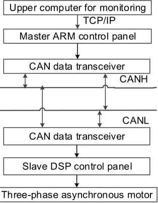
Upper computer for monitoring
Master ARM control panel
CAN data transceiver
CAN data transceiver CANH
CANL
Slave DSP control panel
[image:3.612.230.387.86.288.2]Three-phase asynchronous motor TCP/IP
Figure 1. System structure diagram.
Design of CAN Communication Module of Master Station
As the master station for control, LPC11C14 involves mainly in conversion of Ethernet packet into CAN packet and then sending packet out through CAN bus. LPC11C14 ARM integrates CAN controller and on-chip CAN driver. In addition, CAN controller accesses to 120Ω bus matched resistance at two ends and connect to various slave stations through shielded twisted pair.
VIN GND TXD RXD CANG CANH CANL CTXD CRXD 12 0 Ω 12 0 Ω R1 J2 1 2 CTM8251A
Figure 2. CAN communication module of master station.
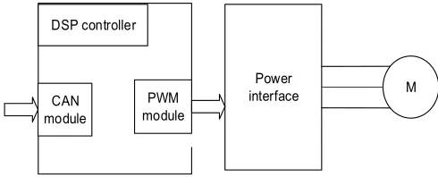
Module Design of Three-phase Asynchronous Motor of Slave Station
As the slave station for control, TMS320F28335 functions mainly as receiving the control command sent from CAN module and motor control through PWM power interface. CAN adopts the timing inquiry mode for communication receiving and sends the data only if required by ARM, to reduce pressure on the system buses and realize real-time control. Its schematic diagram of slave station motor is shown in figure 3.
DSP controller PWM module Power interface M CAN module
Figure 3. Schematic diagram of slave station motor.
System Software Design
[image:4.612.179.424.397.496.2]Scheme 1: only byte packet is transmitted in communication process and 8-byte packet is transferred via TCP to upper computer.
Scheme 2: 16-byte packet is transmitted in communication process and only 8-byte packet is transferred via TCP to upper computer.
Scheme 2 is adopted for packet transmission in the system after comparison of two schemes: transfer CAN’s packet, including the packet composed of ID, length, data section and system time, to ARM, and then ARM transfer the data section and system via TCP to upper computer only. Addition of system time value in packet is to better control the time for receiving the returned packet after a packet request is sent out, and in this way, to calculate the time delay generated in packet transmission link. Moreover, the numbers of packets sent out and received may be compared for statistics of the number of packets lost in transmission link. The format of its packet is shown in figure 4 below.
ID Length Address Status Data Data Time Terminator
Figure 4. Packet format.
The time is encapsulated into packet, to reduce the loss of data in transmission link and improve reliability in data transmission.
Program Design of Master Station
The master station adopts LPC11C14 ARM processor which contains CAN module, so the design of CAN program of master station includes main program design and writing of function program for CAN communication library.
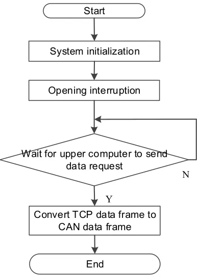
The main program involves mainly in program flow, including initialization function calling, opening interruption and converting TCP’s data frame into CAN’s data frame. The flow chart is shown in figure 5 below:
Start
System initialization
Opening interruption
Wait for upper computer to send data request
Convert TCP data frame to CAN data frame
End
N
[image:6.612.200.393.83.357.2]Y
Interrupt service program
Read CAN state register
Judge whether the sending is interrupted
Wait for completion of data transmission
Y
End of interrupt
Judge whether the receiving is interrupted
N
Read interrupt register number
Y
Call receiver function
System reset
[image:7.612.144.439.88.391.2]N
Figure 6. Flow chart of service program of CAN interrupt function.
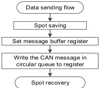
CAN receive data function and CAN send data function are shown in figure 7 and 8 respectively.
Data receiving flow
Spot saving
Set message buffer register
Read the data in register to circular queue of CAN message
Spot recovery
Figure 7. Flow chart of CAN receive data.
Data sending flow
Spot saving
Set message buffer register
Write the CAN message in circular queue to register
[image:7.612.329.490.486.630.2]Spot recovery
[image:7.612.123.279.487.637.2]Program Design of Slave Station
The slave station adopts DSP processor adopts PWM module and enhanced CAN module. The configuration of PWM includes initialization of GPIO port of CAN module, initialization of time base register, and initialization of time base register, phase register and period register, etc. The configuration of CAN includes initialization of GPIO port of CAN module and configuration of receiving email and sending email, etc. In addition to basic PWM and CAN configuration, it also includes the analysis of the 8-digit data after received from CAN module of master station, and different data labels correspond to different functions, including register reading, register writing, file reading and file writing, etc. The function of register reading is to read the motor running state stored in PWM module register, send the value read via CAN module to master station ARM and finally feed it to the upper computer. The function of register writing is to write the command word in CAN packet received into the corresponding register of PWM module, for motor control purpose. File writing is to write the data collected by current and voltage sensor into file. File reading is to transfer the current and voltage values collected to upper computer and then generate the relational graph of current and voltage by use of mat lab.
Program Design of Upper Computer
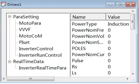
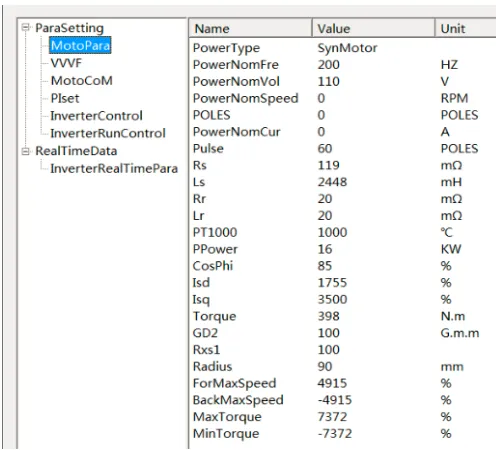
[image:8.612.189.424.451.593.2]The upper computer program adopt development environment of Microsoft Visual Studio 2010 and based on C++ interface, which is shown in figure 9.
Experimental Result
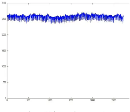
[image:9.612.179.427.302.527.2]If the upper computer sends the commands via TCP/IP to master controller ARM, the state of three-phase asynchronous motor as fed back from controller DSP is shown in figure 10, the reference currents of phase a and c collected by current sensor and reference currents of phase b obtained are shown in table 1 and reference voltage of phase ab and bc collected by voltage sensor and reference voltage of ac are shown in table 2. In the experiment, a total of 32,768 groups of reference values are collected by current sensor, voltage sensor and speed sensor and only the typical values are listed in the experiment form. According to the relational graph of voltage and current created by mat lab and through such 32,768 groups data: the phase difference between voltage of phase a and phase b, phase b and phase c and phase a and phase c, of three-phase asynchronous motor is 120°. Reference speed value collected by speed sensor is shown in table 3 and motor speed is shown in figure 12.
Figure 10. Running state of three-phase asynchronous motor.
TABLE 1. REFERENCE CURRENT OF PHASE A, PHASE B AND PHASE C.
Reference current
1 2 3 4 5
I
a -50 -55 -58 -63 -60I
b 63 70 71 73 73 [image:9.612.192.400.590.668.2]Experiment table1 lists the reference current of phase a, phase b and phase c and the reference current of phase c is the sum of that of phase a and phase b. If the reference current of phase a and phase b is -63 and 73 respectively, it is the current peak of phase a and phase b.
TABLE 2. REFERENCE VOLTAGE of PHASE AB, PHASE BC AND PHASE AC.
Reference voltage
1 2 3 4 5
U
ab -789 -792 -796 -804 -804U
bc 590 570 566 554 542U
ac 199 222 230 250 262Experiment table 2 lists the reference voltage of phase ab, phase bc and phase ac and the reference voltage of phase ac is the sum of that of phase ab and phase bc.
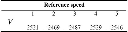
TABLE 3. REFERENCE SPEED COLLECTED BY SPEED SENSOR.
Reference speed
1 2 3 4 5
V
2521 2469 2487 2529 2546
[image:10.612.191.402.380.433.2]Figure 11. Relation between current and voltage.
Figure 12. Diagram of motor speed.
[image:11.612.192.419.330.527.2]CONCLUSION
The system can realize real-time control and state detection on three-phase asynchronous motor and display them via the program of upper computer directly. The entire system has good stability in communication display, except for packet loss in transmission, which should be further researched in the future.
REFERENCES
1. An Hui, An Lin, “Development Path of China’s Industrial Internet”. China Industry Review, 2015(6): 54-58.
2. Lin Shibing, Yuan Yan and Yang Yupu. “Design and Realization of Gateway Between TCP/IP Network and CAN Network”. Computer Engineering, 2015: 33(3): 243-244.
3. Rao Yuntao, Zou Jijun and Wang Jinhong, etc. Theory and Application of Field Bus CAN and Application Technology .Beijing: Beihang University Press, 2007: 1-2.
4. Luo Feng and Sun Zechang. Automotive CAN Bus System Theory, Design and Application. Beijing:Electronic Industry Press, 2010: 29-31.
5. Wang Yuefei, Hou Liang and Liu Fei, etc. “Design of Real-time Management System for Car CAN Network based on FPGA”. Journal of Electronic Measurement and Instrumentation, 2013, 27(8): 721-728
6. Liao Yingsheng. “Design of Air Conditioning Controller based on Automobile CAN Bus”. Mechanical & Electrical Technology, 2015: 2(4): 104-106.
7. Yang Huawei and Fang Zhengquan “Application of CAN Bus in Ship Structure Safety Monitoring System”. Journal of Electronic Measurement and Instrument, 2004, 28(5): 553-559.
8. Ye Mingao, Tan Jianbo and Xiong Yi. “Application of CAN Bus Technology in The Monitoring System for Large Radar”. Foreign Electronic Measurement Technology, 2011, 30(6): 75-78. 9. Jiang Yuefei, Ao Yichao and Jia Yingmin. “A Design of Stepper Motor Controller Based on
ARM-QTE Embedded Technology”. Computer Simulation, 2015, 32(7): 234-238.
10. Xie Sanmao. “Research on Monitoring and Control of Motor Drive System of Hybrid Electric Vehicle”. Computer Measurement & Control, 2014, 22(5): 1407-1409.
11. Xiao Chengdong and Wang Kundong, etc. “DC Motor Control System Based on CAN”. Measurement & Control Technology, 2015, 34 (4): 101-104.
12. W. Richard Stevens. TCP/IP Illustrated Volume 1: The Protocols. Translated by Fan Jianhua, Xu Guanghui and Zhang Tao, etc. TCP/IP Illustrated, Volume 1: The Protocols. Beijing: China Machine Press, 2000.