20th International Conference on Structural Mechanics in Reactor Technology (SMiRT 20) Espoo, Finland, August 9-14, 2009 SMiRT 20-Division V – Modeling, Testing and Response Analysis of Structures, Systems and Components, Paper 2057
Structural Evaluation of Drop Load Effects on Buried Structures
Mehdi S. Zarghamee
a, Keng-Wit Lim
a, and Keith Henshaw
ba
Simpson Gumpertz & Heger Inc., Waltham, MA 02453, USA b
Progress Energy, Crystal River Energy Complex, Crystal River, FL 34438-6708, USA
e-mails: [email protected], [email protected], [email protected]
Keywords: Steam Generator Replacement, Drop Load Analysis, Response Analysis, Structural Evaluation, Soil-Structure Interaction, Finite-Element Analysis
1
ABSTRACT
Buried structures such as cooling water lines and building walls may be subjected to accidental drop load effect during steam generator replacement. A procedure for drop load analysis and evaluation of structural performance of buried structures is presented in this paper. The procedure is based a three-dimensional dynamic soil-structure finite-element analysis. The elastic waves generated by the impact of the drop load on the free surface of the foundation or the soil will propagate through the soil media and deform the buried structure of interest. The foundations and buried structures are modelled so that their nonlinear response can be captured and the results would allow evaluation of certain damage and failure limit states and determination of whether functionality of the structure is compromised. The model accounts for energy dissipation through the soil media and the nonlinear response of the dropping objects, the impacted structure (e.g., foundation) and the buried structures of interest. A case study is presented in which the structural safety and the extent of damage and its effect on functionality of the buried prestressed concrete cylinder pipelines, ductile iron pipelines, and a reinforced concrete wall is assessed for drop components from a steam generator replacement operation.
2
INTRODUCTION
Replacement of steam generators is likely to happen at least once during the service lifetime of pressurized-water reactors. The replacement of old steam generators requires the use of large rigging systems for lifting and moving of the old steam generator out the containment structure and of the new steam generator into the containment structure. These operations are generally performed over an area adjacent to the containment structure where many buried structures and utilities are located.
Safe load paths are planar regions determined for each lifted component during the various stages of lifting operation so as to avoid damage to the buried structures to the extent that would compromise functionality of the critical buried structure, in case of an accidental drop of a lifted component. The critical buried structures are those structures that are needed to remain functional during the generator replacement operation, such as discharge and intake pipelines and electrical instruments and control panels related to cooling system of the fuel elements.
This paper describes an approach that includes a combination of dynamic finite element analyses and structural evaluation of the buried structures, to perform structural evaluation for drop loads occurring during steam generator replacement and arrive at final load paths for safe lifting operations.
3
METHOD OF APPROACH
3.1 Finite Element Model
ABAQUS (2007). Smaller structures are not explicitly modelled; their safety assessment is based on the peak velocity of the soil.
Pipelines are modelled using plate elements. Ductile iron pipes have an elastic-perfectly plastic stress strain diagram in both circumferential and longitudinal direction. Prestressed Concrete Cylinder Pipe (PCCP) is modelled elastically in the circumferential direction and in the longitudinal direction if joints are harnessed. Bell and spigot joints are modelled by assigning a low stiffness to the pipe elements in the longitudinal direction.
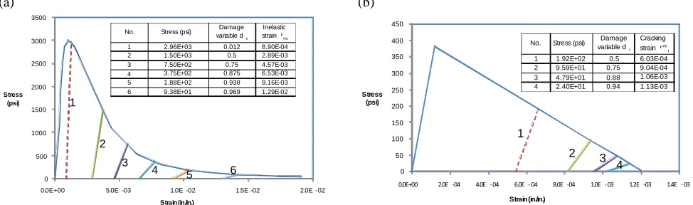
Reinforced concrete structures are modelled using either solid or shell elements. Concrete constitutive model is defined using concrete damage plasticity in ABAQUS. The stress-strain relationship in compression is based on the Saenz model and tensile softening is modelled with a tri-linear curve described in Zarghamee (1990). Degradation of concrete strength under cyclic loading is accounted for by the reduction of the elastic modulus, which is given in terms of a scalar degradation variable d, as a function of compressive and tensile cracking strains. The degradation variable is generally set at approximately 0.98 in both compression and tension, which allows for almost full degradation. Figures 1a and 1b show stiffness degradation in tension and compression.
(a) (b)
0 500 1000 1500 2000 2500 3000 3500
0.0E+00 5.0E -03 1.0E -02 1.5E -02 2.0E - 02
Stress (psi)
Strain (in./in.)
No. Stress (psi) Damage variable dc
Inelastic strain !
inc
1 2.96E+03 0.012 8.90E-04 2 1.50E+03 0.5 2.89E-03 3 7.50E+02 0.75 4.57E-03 4 3.75E+02 0.875 6.53E-03 5 1.88E+02 0.938 9.16E-03 6 9.38E+01 0.969 1.29E-02
1
2
3
4 5 6 0
50 100 150 200 250 300 350 400 450
!"!#$!! %"!# &!' '"!# & !' ("!# & !' )"!# &!' *"!# & !+ *"%# &!+ *"'# & !+ Stress (psi) Strain (in./in.) 1 2 3 4 No. Stress (psi) variable dDamage
t
Cracking strain !ck t
1 1.92E+02 0.5 6.03E-04 2 9.59E+01 0.75 9.04E-04 3 4.79E+01 0.88 1.06E-03 4 2.40E+01 0.94 1.13E-03
Figure 1. (a) Stiffness degradation of concrete in compression. (b) Stiffness degradation of concrete in
tension
Steel reinforcement in concrete is modelled as a rebar layer in shell or solid elements. Energy dissipation is provided through yielding of reinforcement. Increased yield strength of steel reinforcement from dynamic effects of the reinforcement is considered by increasing the yield strength based on the requirements of ACI 349 (2006).
The soil is modelled with solid elements with linear elastic properties. The elastic properties of the soil and unit weights are obtained from measured soil shear modulus and Poisson’s ratio or are estimated based on the soil types encountered at the site and on the presence of ground water. These properties are required for determining the shear and pressure wave speeds in the various soil layers. Energy dissipation in soil media is accounted for through Rayleigh damping, i.e. a linear combination of the stiffness and mass matrices. Damping parameters are determined to provide filtering of nonphysical frequency content above 30 Hz. No damping is used for saturated soil modeled with high stiffness to represent high pressure wave speed in water.
3.2 Boundary Conditions
Infinite elements are provided at the boundaries of the soil model to allow radiation of elastic waves impinging on the boundaries of the finite element model.
3.3 Loads
Prior to drop load analysis, the shapes and sizes of drop objects, and corresponding drop heights and potential energies are identified and sorted based on potential energies. Impact velocity of each drop object is calculated based on the drop height. The impact velocity is applied as an initial condition to the drop object in the finite element model at the time zero. Drop objects are also categorized as to whether they occur during the power operation mode or during the defueling mode. This categorization is important to determine the safety of the buried structure as described below.
For each drop object a number of impact locations are selected based on a preliminary safe load path to provide the worst conditions for the buried structures of interest. For each drop object, both horizontal and vertical configurations at the time of impact are analyzed. The results of different impact points and impact configurations are used to determine the maximum response of the buried structure.
3.4 Safety States
The results of structural evaluation are classified into four states as follows.
a) State 1: Code Compliant. This state consists of structural effects that do not cause
non-compliance with the governing codes.
b) State 2: Not Fully Code Compliant, but Undamaged: This state consists of structural effects
that cause non-compliance with the governing codes, but the structure does not suffer any damage.
c) State 3: Damaged but Functional. This state consists of structural effects that cause damage in
the structure, but the structure remains functional, although at a reduced but acceptable performance level.
d) State 4: Failed: This state consists of structural effects that cause failure and the functionality
of the structure is compromised.
For lifting operations performed during the defueling of the containment unit (Defueled Mode), none of the structures of interest should be categorized under “Failed.” The structure can suffer damage, but should remain functional, although at a reduced but acceptable performance level. For lifting operations performed when the containment unit is in fully powered operation (Power Operation), the structures should remain in the “Code Compliant” or “Not Fully Code Compliant, but Undamaged” states, and “Damaged but Functional” and “Failed” states should not occur. The limit states criteria used to classify the state of the structure depend on the type of structure analyzed; these are described in detail in Section 4.
3.5 Safe Load Path
If the structural evaluation of the buried structures for a load drop shows that safety of the structures of interest cannot be attained and a load drop could result in system failure, the zone of safe load path of the lift operation is accordingly restricted.
4
STRUCTURAL EVALUATION
In this section, the procedures for performing structural evaluation of PCCP, steel pipes, and concrete walls subjected to the combined dead and live load conditions are described.
!"!!#$!! %"!!#$!& '"!!#$!( '"%!#$!( &"!!#$!( &"%!#$!( ("!!#$!( ("%!#$!( )"!!#$!(
!"!!#$!! &"!!# *!( )"!!# *!( +"!!# *!( ,"!!# *!( '"!!# *!& !"#$%%&'(%)*
!"#+),&'),-.),-*
/&0"&12)34&!$3")5,&50&!$+&6+"$#&7558&6+99
-./012.3450678960
-.:"4;8<7"4=/1.294>18<46/./2?4 .9.3@626
A0>B030C4-8C0D4-.:"4;8<7"4=/1.294 EA@9.<2?F
A0>B030C4-8C0D4G8/.34=/1.294 EA@9.<2?4$4=/./2?F
H8I014J701./289D4-.:"4;8<7"4 =/1.294EA@9.<2?F
H8I014J701./289D4G8/.34=/1.294 EA@9.<2?4$4=/./2?F
Figure 2. Combination of concrete stresses and strains resulting from dead and live loads for Power
Operation and Defueled modes.
4.1 PCCP
Structural evaluation of PCCP is performed in both circumferential and longitudinal directions.
In the circumferential direction, the governing code for structural design of PCCP is AWWA C304 (2007). The structural evaluation of PCCP is based on the limit states approach in accordance with the requirements of AWWA C304. AWWA C304 recognizes three different types of limit states of serviceability, structural damage and failure. Each limit state is evaluated when the pipe is subjected to the combined effects of internal working pressure, working plus transient pressure and gravity load effects (such as earth load, pipe and fluid weights, and transient live loads). In addition, a severe damage limit state is included in which the inner core of the PCCP is allowed to crack and fail, causing restriction of flow by not more than 10% of the cross-sectional area of the pipe. This level of flow restriction would not compromise functionality of the pipe. Evaluation of the AWWA C304 limit states is performed using the computer program UDP (2007). Specifically, the ABAQUS output is used for structural evaluation of PCCP in the circumferential direction as follows:
a) Using the finite-element-analysis results, integrate the elemental stresses to calculate the
maximum combinations of circumferential axial force, N, and circumferential bending moment, M, at invert and springline of the pipe for the gravity dead load and for the drop load.
b) Calculate equivalent earth load from the calculated maximum axial force and bending moment
combinations and axial force and bending moment coefficients that load to axial force and bending moment a function of the bedding of the pipe.
c) Determine which limit states are violated in PCCP subjected to combination of internal pressure
and dead and live loads. If all limit states are satisfied, the pipe is “Code Compliant.” The pipe is “Not Fully Code Compliant, but Undamaged” if certain limit states such as core cracking or coating microcracking is violated. Damage corresponds to violation of certain serviceability or damage limit states, including coating cracking, delamination and wire yielding, and severe damage limit state in which the inner core of the PCCP is allowed to crack and fail, causing restriction of the flow by not more than 10% of cross-sectional area of the pipe as described above. The pipe is “Failed” when wires break due to the high strains.
In the longitudinal direction, the structural evaluation is based on comparing the combined axial force and bending moments with the capacities of the pipe as determined from the interaction diagram of the complete pipe cross-section. Specifically, the procedure is as follows:
a) Calculate the maximum longitudinal axial force and bending moment acting on the pipe for
b) Calculate the maximum longitudinal axial force for both tension and compression and bending moment acting on the pipe for drop load.
c) Calculate the sum of the axial forces and bending moments from combined dead and live loads.
d) Compared these stress resultants with the capacities of the pipe as determined from interaction
diagram of the entire pipe wall cross-section.
4.2 Ductile Iron Pipes
The governing code for ductile iron pipe is AWWA Standard C150 (2002) for Ductile Iron Pipe. The combined stresses in ductile iron pipe due to the working pressure and the dynamic loads are checked against the yield strength of ductile iron. AWWA C150 requires a safety factor of 2 against yield for the maximum pressure in the pipe. There is no code requirement for transient dynamic stresses. The criterion that the maximum von Mises stress from the combined static and dynamic loads should not exceed the yield strength of ductile iron was selelcted for evaluation of safety of ductile iron pipes.
For the static condition von Mises stress σS is calculated using the circumferential and longitudinal
stresses from internal pressure. The effect of pipe wall bending in the circumferential direction is neglected because the pipe is flexible and internal pressure tends to reround the pipe, and pipe wall bending is not
considered in the design of the ductile iron pipe. The maximum von Mises stress from drop load analysis σD,
which accounts for circumferential and longitudinal stresses and include the effect of bending of the pipe, are obtained from finite element drop load analysis. The maximum von Mises stress demand from static and
dynamic loads is bounded above by the sum |σS| + |σD|, which is compared to the yield strength of ductile
iron.
4.3 Reinforced Concrete Wall
The structural evaluation of reinforced concrete wall is performed according to ACI 318 (2005). Typically concrete walls are designed for dead load alone without much margin; any margin for the dead plus live load condition is derived from the additional margins that are allowed for dynamic conditions, including an increase p1 in the yield strength of steel due to dynamic loads in accordance with ACI 349 (2006) and an
increase p2 obtained from the differences in load factors of 1.4 for gravity 1.2 for dynamic conditions.
The reinforced concrete wall is Code Compliant if it meets all requirements of ACI 318. The reinforced concrete wall is Not Fully Code Compliant, but Undamaged, when subjected to the combined dead and live load condition, if the strain from the combined dead and live load condition does not exceed 0.2%. At this strain limit, the capacity of the wall is reached in compression prior to the onset of compressive cracking and crushing of concrete, and visible cracks occur in tension, but such cracks will not degrade the strength of the wall. The reinforced concrete wall is Damaged but Functional, when subjected to the combined dead and live load condition, if the strain from superimposed dead and live load condition exceeds 0.2%, but is less than about 0.5%. Under this condition, compressive cracks and tensile cracks are expected to exist in the wall, but strength degradation is limited and small. In addition to cracking, there may be small pieces of concrete spalling or scabbing off the wall. Unstable failure and collapse of the wall is not likely. The reinforced concrete wall is Failed if the strain from superimposed dead and live load condition exceeds 0.5%.
To calculate the maximum displacement of the wall under the superimposed static and dynamic condition, the deflection from drop load analysis is increased by the ratio of the sum of static and dynamic strain to the dynamic strain.
Case Study – Crystal River Nuclear Power Plant, Unit 3
4.4 Drop Objects
A total of 42 drop load cases were identified and analyzed, accounting for impact location, impact angle (whether the drop object impact position is vertical or horizontal, which also affects drop height), and whether they are dropped during the Power Operation or Defueled modes. The highest potential energy is 92,104 kip-ft due to the horizontal impact of the steam generator (SG), with a weight of 1,160,000 lbs and drop height of 79.4 ft. The impact of steam generator falling off the self-propelled modular transporter (SPMT), at a smaller potential energy of 8,990 kip-ft, is also considered.
Other impact objects are assembly beams and components of the lifting systems. The potential energies of these objects range from 119 kip-ft to 14,247 kip-ft, depending on the weight and fall height.
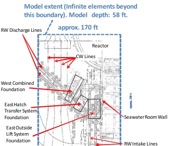
Impact of drop objects on the reinforced concrete foundations supporting the lifting systems is also considered. These foundations are the West Combined Foundation, East Hatch Transfer System (HTS) Foundation and East Outside Lift System (OLS) Foundation, as shown in Figure 3.
East Outside Lift System Foundation
Seawater Room Wall RW Discharge Lines
Reactor
Model extent (Infinite elements beyond
this boundary). Model depth: 58 ft.
RW Intake Lines East Hatch
Transfer System Foundation West Combined Foundation
approx. 170 ft
CW Lines
Figure 3. Schematic showing the extent of computational domain, with locations of primary structures of
interest.
4.5 Finite Element Analysis
A three-dimensional finite element model of the soil, pipelines, foundations, and Sea Water Room Wall is developed using ABAQUS (2007) as shown in Figure 4. Prior to dynamic analyses, a static finite element analysis was performed to study the installation loads due to cranes, mobile crane, and foundations on the RW PCCP lines. These results were combined with results from the drop load analysis. For the other structures, the static responses were estimated using UDP and by manual calculations.
(a) (b)
Figure 4. Finite element model for drop load analysis: (a) soil model and (b) buried structures.
4.6 Structural Evaluation
4.6.1 48 in. and 90 in. Diameter PCCP
The 48 in. diameter RW PCCP lines were subjected to the combined effects of static loads from a prior static finite element analysis and drop loads from the dynamic analyses. For each drop load case the extent of damage is discussed and ability of the line to function is evaluated based on the approach described in Section 4.1. At least one of the two RW PCCP lines must remain functional during the Defueled Mode.
In the longitudinal direction, Flex Tied Clamp Type Joints are use for mechanical harnessing of the joints. The mechanical harnessed joints typically allow about 1/8 to 3/16 in. of joint opening when subjected to an axial tensile force. A joint opening of 1/8 or 3/16 in. is much greater than the opening demand of 0.013 in. for full relief of longitudinal force in the pipe. Therefore, longitudinal tensile force would not develop in the pipe provided that the movement does not exceed 0.013 in. The bending moment and axial force in the entire pipe cross-section is conservatively calculated neglecting the ability of the pipeline to accommodate relative rotation or extension at the joints.
Structural evaluation of the 90 in. diameter CW PCCP lines was performed following the same procedure as described for the RW PCCP lines. Failure of this line was not deemed detrimental to the plant operation during the defueling outage.
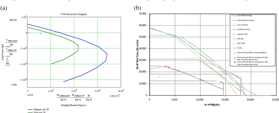
Typical interaction diagrams obtained from the computer program UDP are shown in Figure 5.
(a) (b) !"#$%#&'(#)&'*# +,-#./0&'12&'*3
% 4%5%%% 6%5%%% 7%5%%% 8%5%%% 9%5%%% :%5%%% ;%5%%%
% 95%%% 4%5%%% 495%%% 6%5%%% 695%%%
!"#$%&'()*+,-.
#&
%/
0%
12
3"
'()
4+,
*+
,-!<0*#=&>0<>0?>@&'1
!<?-&'1#=&>0<>0?>@&'1
!<0*#!0?>@&'1
!<?-&'1#!0?>@&'1
!A2&'B*0#C&*2B
"&0*#DE1
"&0*#C&*2B
%(;9DF>
G*H?'B#)<?B5#I*D<0*#G0</#+./0&'12&'*3
G*H?'B#)<?B5#,D-*0#G0</#+.*1H*'-#J&-K =&'(#!&0>LHD*0*'-&?2#M<0>*3 G*H?'B#)<?B5#,D-*0#G0</#+.*1H*'-#J&-K =?N(#!&0>LHD*0*'-&?2#M<0>*3
Figure 5. Interaction diagram for PCCP pipes: (a) longitudinal and (b) circumferential directions.
4.6.2 48 in. Diameter Ductile Iron Pipes
of earth load and foundation live load were neglected because the pipe is flexible and is under internal pressure that tends to reround the flexible pipe. Analysis is based on calculation of maximum von Mises stress and comparison with yield strength of the ductile iron. The RW Intake Line remains code compliant for all cases analyzed.
4.6.3 Sea Water Room Wall
The strains from a previous static analysis are less than or equal 641 micro in./in. in the 2 ft thick section and 478 micro in./in. in the 3 ft thick section of the wall
In the Power Operation mode, the dynamic strains are limited to 1,365 micro in./in. in the 2 ft thick section and 374 micro in./in. in the 3 ft thick section of the wall, which are less than the estimated elastic strain limit of 2,000 micro in./in. The sum of the static and dynamic strains are approximately 2,000 micro in./in. for the 2 ft thick section and 852 micro in./in. for the 3 ft thick section of the wall, which are within the linear regime. The Sea Water Room Wall is not code compliant but considered undamaged for all drop loads under Power Operation.
In the Defueled Mode, the worst condition is due to the SG horizontal impact on the East HTS Foundation, in which the dynamic strain is 3,790 micro in./in. (2 ft thick section) and 3,280 micro in./in. (3 ft thick section). The superposition of static and dynamic conditions in the Defueled Mode is based on the sum of energies, which is the basis of ductility concept used in ACI 349 (2006). These results in a superimposed static plus dynamic strains of 4,140 micro in./in. for the 2 ft thick section and 3,430 micro in./in. for the 3 ft thick section of the wall. The strain in the 2 ft section of the wall corresponds to deflection and cracking in tension and compression and likely spalling and minor scabbing of the wall, but not its collapse or failure. For all other drop cases in the Defueled Mode, the dynamic strains are smaller.
4.6.4 Safe Load Paths for Lifting Operations
Based on the analyses and evaluation outcomes, the existing safe load paths for the client’s final lifting operations were modified.
5
CONCLUSION
An approach based on finite element analysis of soil-structure interaction is developed for structural evaluation of buried structures subjected to drop load impact effect is presented. Specifically, the approach allows one to:
a) Identify the effect of drop load based on drop location, drop height, weight, and position of drop
objects in both Defueled and Power Operation Modes.
In this approach, stress wave propagation, contact-impact phenomena arising from accidental dropping of components during the steam generator replacement operations, energy dissipation through yielding of steel reinforcement, concrete cracking, and damping of stress waves in the soil media are modelled The results of drop load analysis (structural deflections, bending moments, and axial forces) are then used for to structural evaluation considering serviceability, damage, and failure limit states.
b) Classify damage levels of buried structures into four levels: “Code Compliant”; “Not Fully
Code Complaint, but Undamaged”; “Damaged, but Functional”; and “Failed.”
c) Verify, modify, and/or provide new safe load paths for lifting operations to avoid failure of the
structural systems that need operate during accidental drop loads.
REFERENCES
ABAQUS. 2007. ABAQUS version 6.7. Simulia, Dassault Systèmes.
American Concrete Institute. 2005. Building Code Requirements for Structural Concrete, ACI 318.
American Water Works Association. 2002. Standard for Thickness Design of Ductile-Iron Pipe, AWWA C150.
American Water Works Association. 2007. Standard for Design of Prestressed Concrete Cylinder Pipe, AWWA C304.
American Water Works Association. 2008. Concrete Pressure Pipe, AWWA Manual M9.
UDP Program. 2007. Developed by SGH for the American Concrete Pressure Pipe Association