ABSTRACT
SWANEY, PAUL MICHAEL. Target and Core Optimization for an Electron
Accelerator-Driven Transmutation Facility. (Under the direction of Dr. Man-Sung Yim.)
The current statutory limit for Yucca Mountain is quickly being met by waste
produced at the reactors operating in the United States. A possible method of modifying
reactor waste for more efficient storage in Yucca Mountain is transmutation. This study
analyzes the use of an electron accelerator targeting its beam on a neutron producing
target within a subcritical reactor fueled with transuranic waste from power reactor
operations.
To maximize the transmutation effectiveness of the design, several loading
patterns were analyzed for neutronics behavior and transmutation effectiveness. Designs
utilizing multiple batches of fuel or multiple targets within the core were also analyzed.
The loading pattern analysis showed no clear beneficial loading pattern for the
neutronics of the core; however, the results indicated that placing Curium within the
innermost fuel assemblies improved the transmutation effectiveness of the core. The
most effective loading pattern in terms of neutronics and transmutation effectiveness
utilized Curium assemblies in the innermost locations, Americium assemblies in the
second ring, and Neptunium and Plutonium assemblies in the outermost locations.
The use of multiple batches in the core layout demonstrated superior neutronics
behavior but lacked in transmutation effectiveness. On the other hand, the use of
multiple targets in the core did not exhibit the lower peaking factors expected and also
designs should be combined with more effective loading patterns to maximize their
benefits.
When comparing electron accelerator based systems with proton accelerator
based systems, the proton based systems have a significant advantage due to the higher
neutron production efficiency within the target. However, economic and timeline
considerations make the deployment of electron based systems attractive in specific
Target and Core Optimization for an Electron Accelerator-Driven Transmutation Facility
by
Paul Michael Swaney
A thesis submitted to the Graduate Faculty of North Carolina State University
in partial fulfillment of the requirements for the Degree of
Master of Science
Nuclear Engineering
Raleigh, North Carolina
2007
APPROVED BY:
_________________________ _________________________ Dr. David McNelis Dr. Ernie Stitzinger
________________________________ Dr. Man-Sung Yim
BIOGRAPHY
Paul Swaney was born in Statesville, North Carolina in the United States. He
received his bachelor of science degrees in Nuclear Engineering and Applied
Mathematics from North Carolina State University (NCSU) in May 2006.
Paul began work on his Master of Science degree in Nuclear Engineering in
August of 2006 working under the direction of Dr. Man-Sung Yim at NCSU. Paul was
also mentored in his work by Dr. David McNelis from the University of North
Carolina-Chapel Hill. Paul’s research included analyzing various core loading designs for an
electron accelerator-based transmutation facility.
Paul loves playing soccer, annoying his cat Lily, and spending time with his
friends. Paul plays in the co-ed and men’s leagues of the triangle adult soccer league
based out of Raleigh, NC. Lily is a domestic long hair cat that hates to be petted. A lot
of his friends are nerdy nuclear engineers as well, such as Jason Elkins, Tyler Schweitzer,
his future roommate Brandon Clark, and Hope Gwatney; however, some of them are
ACKNOWLEDGEMENTS
The first people I would like to thank are my family members who have been
supportive of me throughout my entire educational career. This extension of gratitude
includes a thank you to my baby sister, Laura who made me go to half-priced sushi nights
so often when I had other work to do.
I would also like to thank Dr. Man-Sung Yim and Dr. David McNelis who have
both been very supportive during my work. Without their guidance and patience, I would
not have been able to complete such an undertaking. Their patience and instructions
during the weekly research meetings were my motivating factors throughout the project.
I also appreciate the support of my math advisor Dr. Ernie Stitzinger, who worked with
me on various administrative difficulties that arose during the completion of my math
minor.
I would also like to thank all my friends who kept distracting me from my work.
In particular, Brandon Clark and Jason Elkins for all the green tea runs, Peggle
tournaments, and beta outings. Thank you as well to Hope Gwatney, my faithful research
meetings secretary and beach buddy.
This research was financially supported through The Russell Family Foundation
TABLE OF CONTENTS
LIST OF TABLES ... vi
LIST OF FIGURES ... vii
1 INTRODUCTION ... 1
1.1 SPENT NUCLEAR FUEL DISPOSAL... 1
1.2 SNFCOMPOSITION... 2
1.3 LIMITING FACTORS FOR REPOSITORY CAPACITY... 4
1.4 TRANSMUTATION... 7
1.5 POSSIBLE METHODS OF TRANSMUTATION... 8
1.6 ACCELERATOR DRIVEN TRANSMUTATION SYSTEM... 12
1.7 PROPOSED SCOPE OF WORK... 14
2 REVIEW OF PREVIOUS WORK ... 16
2.1 TARGET DESIGN... 16
2.2 ACCELERATOR BEAM... 23
2.3 NEUTRON SPECTRUM... 25
2.4 FUEL MATERIALS... 33
2.5 CORE COOLANT... 40
2.6 MEASURES OF TRANSMUTATION EFFECTIVENESS... 45
3 CONCEPTUAL ADS DESIGN... 48
3.1 TARGET DESIGN... 48
3.2 ACCELERATOR BEAM... 49
3.3 NEUTRON SPECTRUM... 49
3.4 FUEL MATERIALS... 49
3.5 CORE COOLANT... 50
3.6 MODIFIED ALMRCORE DESIGN... 50
3.7 FAST REACTOR FUEL ISOTOPICS... 53
3.8 LOADING PATTERNS FOR FAST REACTOR ANALYSIS... 57
3.9 MULTIPLE BATCH CORE DESIGN STUDY... 64
3.10 MULTIPLE TARGET DESIGN STUDY... 66
3.11 INGESTION RADIOTOXICITY AND HEAT LOAD REDUCTION PARAMETER... 68
4 METHODOLOGY ... 70
4.1 CODES UTILIZED... 70
4.2 BENCHMARK... 72
4.3 ANALYSES PERFORMED... 74
5 RESULTS ... 76
5.1 NEUTRONICS RESULTS AND DISCUSSION FROM LOADING PATTERN ANALYSIS. 76 5.2 TRANSMUTATION RESULTS AND DISCUSSION FROM LOADING PATTERN ANALYSIS... 83
5.3 RESULTS AND DISCUSSION FROM MULTIPLE BATCH ANALYSIS... 87
6 CONCLUSIONS ON ELECTRON ADS ... 91
6.1 LOADING PATTERN ANALYSIS CONCLUSIONS... 91
6.2 OVERALL CONCLUSIONS ON ELECTRONADS... 93
7 COMPARISONS OF PROTON AND ELECTRON ADS ... 95
7.1 NEUTRON PRODUCTION EFFICIENCY... 95
7.2 BURNUP CHARACTERISTICS... 98
7.3 ECONOMIC AND TIMELINE CONSIDERATIONS... 102
8 CONCLUSIONS... 105
LIST OF TABLES
Table 1: Candidate ADS Target Materials... 18
Table 2: Target Material Neutron Production Efficiency Results12... 20
Table 3: Neutron Yield per Incident Electron for Various Target Sizes12... 22
Table 4: High Energy Electron Accelerators ... 24
Table 5: Comparison of Solid and Liquid Fuel Forms for a Fast Spectrum ADS20... 34
Table 6: Advantages and Disadvantages of Metal Alloy Fuels20... 35
Table 7: Advantages and Disadvantages of Nitride Pellet Fuels20... 36
Table 8: Advantages and Disadvantages of Dispersion Fuels20... 37
Table 9: Advantages and Disadvantages of TRISO Coated Fuels20... 38
Table 10: Reactor Design Characteristics... 53
Table 11: Overall TRU Fuel Isotopics and for Np-Pu-Am-Cm Fuel Assemblies... 54
Table 12: TRU Isotopics in Np-Pu Fuel Assemblies... 55
Table 13: TRU Isotopics in Am-Cm Fuel Assemblies ... 55
Table 14: TRU Isotopics in Am Fuel Assemblies ... 55
Table 15: TRU Isotopics in Cm Fuel Assemblies ... 56
Table 16: Loading Pattern Summary ... 63
Table 17: Isotopics of Once Burnt Fuel... 64
Table 18: Isotopics of Twice Burnt Fuel ... 65
Table 19: Comparison of Reference 10's LP1 keff Results with New Input File’s Results73 Table 20: Comparison of Reference 10's LP9 keff Results with New Input File’s Results73 Table 21: Comparison of Reference 10's LP19 keff Results with New Input File’s Results ... 74
Table 22: Loading Pattern Summary ... 77
Table 23: Loading Pattern keff Results ... 78
Table 24: Loading Pattern Peaking Factor Results... 80
Table 25: Loading Pattern Radioactivity Data... 84
Table 26: Loading Pattern Heat Load Data ... 85
Table 27: Loading Pattern Radiotoxicity Data ... 86
Table 28: Loading Pattern Radiotoxicity Data ... 87
Table 29: Multiple Batch Analysis Results ... 88
Table 30: Multiple Target Analysis Results ... 90
Table 31: Overall Transmutation Rates for Four ADS Systems... 99
Table 32: Reactor-years required to transmute 63,000MTHM of SNF worth of each element... 100
LIST OF FIGURES
Figure 1: Constituents of Spent Nuclear Fuel3... 3
Figure 2: Ingestion Toxicity of SNF Constituents with Time5... 5
Figure 3: Decay Heat Generated by SNF and Constituents6... 6
Figure 4: Simplified Schematic of an ADS10... 12
Figure 5: Target Material Neutron Production Efficiency Results [10] ... 19
Figure 6: Target Material Neutron Production Efficiency Results12... 21
Figure 7: Np-237 Cross Sections (Fission-Brown; Capture-Green)... 26
Figure 8: Pu-238 Cross Sections (Fission-Brown; Capture-Green) ... 27
Figure 9: Pu-239 Cross Sections (Fission-Brown; Capture-Green) ... 27
Figure 10: Pu-240 Cross Sections (Fission-Brown; Capture-Green) ... 28
Figure 11: Pu-241 Cross Sections (Fission-Brown; Capture-Green) ... 28
Figure 12: Pu-242 Cross Sections (Fission-Brown; Capture-Green) ... 29
Figure 13: Am-241 Cross Sections (Fission-Brown; Capture-Green)... 29
Figure 14: Am-242m Cross Sections (Fission-Brown; Capture-Green)... 30
Figure 15: Am-243 Cross Sections (Fission-Brown; Capture-Green)... 30
Figure 16: Cm-244 Cross Sections (Fission-Brown; Capture-Green)... 31
Figure 17: Cm-245 Cross Sections (Fission-Brown; Capture-Green)... 31
Figure 18: Cm-246 Cross Sections (Fission-Brown; Capture-Green)... 32
Figure 19: Cm-247 Cross Sections (Fission-Brown; Capture-Green)... 32
Figure 20: Center Assembly with Target Location... 52
Figure 21: LP1 Core Layout; Blue:Np-Pu-Am-Cm... 57
Figure 22: LP2 Core Layout; Blue:Np-Pu, Red:Am-Cm ... 58
Figure 23: LP3 Core Layout; Blue:Np-Pu, Red:Am-Cm ... 59
Figure 24: LP4 Core Layout; Blue:Np-Pu, Red:Cm, Orange:Am... 60
Figure 25: LP5 Core Layout; Blue:Np-Pu, Red:Cm, Orange:Am... 61
Figure 26: LP6 Core Layout; Blue:Np-Pu, Red:Cm, Orange:Am... 61
Figure 27: LP7 Core Layout; Blue:Np-Pu, Red:Cm, Orange:Am... 62
Figure 28: LP8 Core Layout; Blue:Np-Pu, Red:Cm, Orange:Am... 62
Figure 29: LP9 Core Layout; Blue:Np-Pu, Red:Cm, Orange:Am... 63
Figure 30: Multiple Batch Core Layout; Blue-Fresh Fuel, Red-Once Burnt, Orange-Twice Burnt ... 66
Figure 31: Multiple Target Core Layout... 67
Figure 32: Loading Pattern keff vs Time ... 79
1 INTRODUCTION
1.1 SPENT NUCLEAR FUEL DISPOSAL
In the United States, approximately 20% of electrical demand is met through
nuclear power generation. There are currently 104 reactors operating within the US to
meet this demand. During operations, nuclear reactors produce spent nuclear fuel (SNF)
which is toxic, highly radioactive, and has high heat generation rates. The characteristics
of SNF require special disposal methods to ensure public safety. In 1957, the US
government began to look for an acceptable method to dispose of SNF waste. In the
Nuclear Waste Policy Act of 1982, the US government decided a mined geological
repository was the preferred method for disposal of high-level nuclear waste, including
SNF.1
In 1983, the DOE began considering nine sites for use as repositories for nuclear
waste. The DOE reduced the number of sites under consideration to five in 1986. Later
that year, the Secretary of the DOE recommended three sites to the President for further
consideration. In 1987, Congress amended the Nuclear Waste Policy Act. Under the
amendment, Congress instructed the DOE to cease site characterization studies for the
Hanford, Washington and Deaf Smith County, Texas sites. Yucca Mountain, Nevada
became the only site studied by the DOE for use as a nuclear waste repository.1
Investigations into the feasibility of placing a geological repository in the
Southwest began in the 1970s. In 1976, the director of the United States Geological
Survey suggested several sites around the Nevada Test Site as possible candidates for a
repository. Site characterization of Yucca Mountain started in 1986 and is ongoing
The Nuclear Waste Policy Act limits the capacity of Yucca Mountain to 70,000
MTHM. This limit includes contributions from commercial SNF, SNF from research
reactors, and High Level Waste from defense activities. Current plans allocate 63,000
MTHM of the limit to storing SNF from commercial reactor operations.1 With the
current fleet of operating reactors within the US, the limit for commercial SNF will be
reached in 2014.2 However, it is safe to assume most reactors will be operating beyond
2014 and new reactors will be built in the future. Therefore, the current legal capacity of
Yucca Mountain for commercial SNF is not sufficient. However, given the past legal and
regulatory complications associated with the construction of the repository at Yucca
Mountain, there will likely be only one repository built in the US. Therefore, utilizing
transmutation technologies to reduce the amount of waste to be disposed of at Yucca
Mountain is important.
1.2 SNF COMPOSITION
In order to determine a method for increasing the capacity of Yucca Mountain, the
factors limiting Yucca Mountain’s capacity must be analyzed. All commercial reactors
operating in the US today are light water reactors (LWRs). An LWR uses fuel composed
of enriched uranium to generate electricity. The enriched uranium is composed of ~5%
235
U and 95% 238U by weight. During fuel utilization within the reactor, the fission
process transmutes the uranium primarily into fission products (FPs) and isotopes with
higher atomic numbers. Isotopes with higher atomic numbers than uranium are termed
transuranics (TRUs). However, the largest component of SNF is uranium, composing
95.5% of the SNF. The uranium in SNF is ~0.8% 235U by weight, slightly higher than
Plutonium and the minor actinides (MA) represent the TRUs present in SNF. The stable
or short-lived fission products, and other long-lived fission products represent the FPs
present in SNF and account for all material besides uranium and TRUs.
Figure 1: Constituents of Spent Nuclear Fuel3
The TRUs in SNF are produced by neutron capture and beta decay within the
reactor. Neutron capture, which usually occurs as a (n,γ) reaction, results in new isotopes
of the same element being produced. Beta decay increases the atomic number of the
atom but maintains the same mass number. Therefore, for instance, in a reactor when
238
U undergoes a neutron capture, 239U is produced. 239U then goes through beta decay to
produce 239Np which then beta decays into 239Pu, the most abundant isotope, other than
238
U, in SNF. All of the TRUs in SNF are produced in similar ways and they are all
unstable. The unstable TRUs decay via alpha decay, beta decay, or spontaneous fission,
although beta decay is the dominant mode.
Fission products are the resulting atoms from the fission processes occurring
within a nuclear power reactor. Most FPs present in SNF are produced either directly
neutron rich and therefore undergo beta decay to increase stability. There are several
hundred different isotopes produced as FPs in a nuclear reactor.4
1.3 LIMITING FACTORS FOR REPOSITORY CAPACITY
The limiting factors for a geological repository are the radiotoxicity and heat
generation of the SNF placed in the repository. Since all TRUs and most FPs are
unstable, and therefore decay, they contribute to the radioactivity and heat generation of
the SNF.
The radiotoxicity of the SNF is an indication of the potential adverse effects
radiation from the SNF will have on living organisms.4 The intake of radionuclides can
occur for humans through two major pathways, inhalation and ingestion.
When analyzing the proposed Yucca Mountain repository, the most likely
pathway for the release of the SNF to the environment is by ground water transport.
Some of the radionuclides are water soluble and can be transported in the ground water
away from the original disposal site. The radionuclides can then be ingested by either
drinking the contaminated ground water or eating any food that relied on the
contaminated ground water as its water supply.4 Therefore, ingestion is the primary
hazard associated with the disposal of SNF in the Yucca Mountain repository. Figure 2
shows the total ingestion toxicity of SNF will not have decreased to the level of natural
uranium after a million years. The fission products 99Tc and 129I, both water soluble, are
concerns for potential health risks due to their high migration rate in ground water.
237
Np, a TRU, is also of particular concern for its possible health effects. 237Np can
become more soluble in ground water depending on the pH level and oxidizing potential
Figure 2: Ingestion Toxicity of SNF Constituents with Time5
The second factor limiting performance at Yucca Mountain repository is the
decay heat generated by the SNF. When the various isotopes decay, heat is generated.
The heat generation within the fuel raises the fuel temperature and the mountain’s
temperature around the fuel. However, due to fuel integrity and groundwater transport
between drifts concerns, there are statutory limits on the maximum temperature allowed
at various locations within the repository. Therefore, the heat generation of the SNF
limits the amount of waste that can be placed within the repository while still meeting the
function of time. On the figure, the decay heat attributed to various components such as
actinides and 90Sr+137Cs are identified. [References on Figures]
Figure 3: Decay Heat Generated by SNF and Constituents6
Figure 3 demonstrates that 90Sr and 137Cs dominate the decay heat generation by
SNF in the short term (~100 yrs); however, in the long term the actinides present in the
products present in SNF. Therefore, when analyzing the radiotoxicity and heat
generation of the SNF constituents, it is clear that 90Sr, 137Cs, 90Tc, 129I, uranium, and the
TRUs are the components threatening repository performance due to the ingestion
radiotoxicity and heat generation of these isotopes.
1.4 TRANSMUTATION
Transmutation is the conversion of one isotope into another of the same or a
different element. The isotopes threatening repository performance mentioned above
were created by transmutation of fuel within a nuclear reactor. However, further
utilization of transmutation can help alleviate the impact certain isotopes will have on the
repository performance. Transmutation can convert the most damaging isotopes into
isotopes that are less radiotoxic, produce less heat, have shorter half lives or are stable.
Transmutation can be induced by bombarding a material with various particles including
alpha and beta particles, photons, or neutrons. Due to the high coulomb barrier
associated with charged particle interactions and low photon cross-sections of the
isotopes of interest, this study focuses on the use of neutrons for the required
transmutations.
Neutron induced transmutation can be implemented in various methods using
either a fast or a thermal flux. However, for 90Sr and 137Cs both the fast and thermal
cross-sections are small enough to discourage transmutation. 90Sr and 137Cs are also two
of the relatively shorter live isotopes mentioned affecting repository performance.
Therefore, the scope of this study has been reduced to investigations regarding the
transmutations concepts fuel reprocessing is assumed and therefore the uranium present
in SNF is assumed to be recycled and reused in the fuel cycle.4
99
Tc and 129I decay quickly to stable isotopes after neutron capture. 99Tc and 129I
have high neutron capture cross-sections in the thermal region. Therefore, using a
thermal flux for transmutation would be most effective for the fission products 99Tc and
129
I. Neutron capture does not result in stable isotopes or a beneficial decay chain for the
most abundant TRUs in SNF. Fission is the most effective means of transmutation for
the TRUs. The fission cross-section for the TRUs is lower in the thermal region than in
the fast region. In addition, the capture cross-section for TRUs is high in the thermal
range. For any transmutation setup requiring effective neutron multiplication (criticality),
the ratio of neutron capture cross-section to fission cross-section becomes more important
than the value of the fission cross-section alone. The capture to fission ratio for most of
the TRUs is higher for a fast neutron spectrum than a thermal spectrum.7
1.5 POSSIBLE METHODS OF TRANSMUTATION
Transmutation can occur by bombarding the target material with a number of
incident particles. However, for heavier elements the coulomb barrier requires uncharged
particles for practical transmutation rates. This study concentrates on the bombardment
of fission products and TRUs from SNF waste with neutrons. There are many possible
designs utilizing neutron bombardment for the transmutation of fission products and
TRUs from SNF. The methods for neutron-induced transmutation can be broken down
into categories based on the energy range of the neutron flux utilized. Therefore, the
three main categories for transmutation methods utilize thermal, epithermal, and fast
The most common method of transmutation proposed for components of SNF is
the placement of the material into an operating reactor. The reactor provides a neutron
flux on its periphery that is utilized to transmute the waste. Depending on the reactor
design, the SNF can be exposed to a thermal, epithermal, or neutron spectrum. An
example of transmutation utilizing a thermal flux from an operating reactor is the MOX
program currently operating in the US. MOX assemblies utilize excess plutonium
reserves from weapons programs or, if reprocessing is reintroduced in the US, from
recycled materials, for fuel. The goal of the weapons-related project is a joint effort by
the US and Russia to reduce the available amount of weapons grade plutonium. The
plutonium is transmuted into other isotopes during its utilization for energy production
within modified power reactors. The MOX program is an example of thermal
neutron-induced transmutation; however, for reducing the radiotoxicity of the SNF the MOX fuel
cycle is not very efficient. The plutonium component of the MOX fuel is greatly
reduced, but other TRUs are produced in the process.8
Nuclear reactors can also provide epithermal and fast neutron fluxes for SNF
transmutation. The placement of SNF constituents into a fast reactor would expose the
waste to transmutation via a fast neutron flux bombardment. As mentioned above,
exposure in a fast neutron flux is not practical for the fission products of interest.
However, it is possible to transmute the TRUs present in the fast flux of an operating
reactor. Another possibility is the placement of the fission products of interest within a
moderating medium on the periphery of the fast reactor core. Therefore, the TRUs can
be transmuted within the fast flux in the interior of the core while the fission products are
SNF constituents to an epithermal neutron flux within a reactor system is also possible.
The most likely method for accomplishing an epithermal flux for transmutation purposes
is the use of a reactor with a fast neutron flux. This can be accomplished by placing
moderating material in the area of the SNF constituents within the reactor. For example,
the use of CaHx has provided high transmutation rates for 99Tc in some reactor
experiments.9
Utilization of reactors for neutron-induced transmutation of SNF benefits from the
economics associated with energy production within a reactor system. Another benefit of
using a reactor for transmutation is the neutron multiplication that occurs within the
reactor system. The neutron multiplication within the reactor core increases the neutron
flux to which the SNF is exposed. However, transmutation within reactor systems
requires a critical reactor core to operate. And operation of a reactor requires the
criticality and safety requirements to be met. In order to maintain criticality within a
reactor system, fuel containing fertile isotopes is typically used; however, fertile fuel
produces waste during the reactor operations. If the primary objective of a transmutation
facility is the reduction of waste for disposal, the utilization of a reactor system for
transmutation is not very efficient due to the production of additional waste when using
fertile fuels.
A possible design for transmutation that does not require the use of fertile fuels is
an accelerator. The energy spectrum of the neutrons produced in an accelerator system
can be determined prior to construction and therefore tailored for the most efficient
transmutation of the SNF isotopes of interest. However, an accelerator system does not
accelerator system is substantially lower than what is observed in a reactor system.
Therefore, the neutron flux the waste experiences is limited to the capacity of the
accelerator setup. The second major drawback to using an accelerator for transmutation
is the energy required to operate the system. With a reactor system, energy is required to
operate the plant; however, energy is also produced and can be utilized for electricity
production. The sale of electricity from a reactor system can easily offset and surpass the
cost of operating the plant. A pure accelerator system cannot reclaim the amount of
energy used during particle acceleration from the target interactions.
A third possible method for producing neutrons to use for SNF transmutation
involves coupling the reactor and accelerator systems together in order to gain the
benefits of both systems. This setup, known as an Accelerator Driven System (ADS),
uses an accelerator beam of either electrons or protons to strike a target within a
subcritical reactor core. When the accelerator beam strikes the target, neutrons are
produced which bring the reactor up to criticality. An ADS has the benefits of neutron
multiplication and power production provided from having the sub-critical core while
eliminating the need for fertile fuel due to the extra source of neutrons from the
accelerator and target. The extra source of neutrons provided by the accelerator and
target also allow for greater flexibility in the fuel design of the reactor core. Another
benefit of the ADS is the safety feature provided by the accelerator and reactor coupling.
Since the reactor core is designed to be subcritical at all times except when the extra
source of neutrons is present, the reactor can easily be shutdown by turning off the
accelerator beam. Shutting down the accelerator is a dependable method for returning the
1.6 ACCELERATOR DRIVEN TRANSMUTATION SYSTEM
The ADS concept attempts to bring together the advantages of a reactor system
with those of an accelerator system. The ADS has the potential of neutron multiplication
within the core which would increase the neutron flux to which the SNF waste is
exposed. Like the power reactor system, the ADS also has the ability to generate
sufficient heat for power production. The electricity production provided by the ADS
system can be used to operate the accelerator system and any excess can be sold to
support the overall operational and capital costs of the system. However, unlike a typical
reactor system, the ADS does not require fertile fuel for sufficiently long cycle lengths.
The accelerator part of the system provides an extra source of neutrons that can maintain
criticality as the keff of the fuel decreases during transmutation. Figure 4 shows a
simplified view of how an ADS is structured.
There are two possible types of ADSs that can be utilized for SNF transmutation.
The accelerator part of the system can be either an electron or a proton accelerator. An
electron ADS uses Bremsstrahlung interactions within the target to produce the desired
neutrons. The high-energy electrons interacting with the target material via
Bremsstrahlung create a cascade of photons within the target. The photons then induce
photon-neutron interactions (γ,n), producing neutrons, which are supplied to the
surrounding subcritical reactor. On the other hand, the proton ADS uses the spallation
process to generate the desired neutrons. The high-energy protons interact directly with
the nuclei of the target material. Neutrons are ejected from the impacted nuclei and
eventually are utilized with the subcritical reactor.
Either choice of beam particle has benefits over the other. Currently, a proton
ADS is more efficient at producing neutrons in a target per incident proton from the
accelerator. On the other hand, there is more of an experience base for electron
accelerators. Electron accelerators are more widely used in the U.S. and, therefore, the
experience base and development progress for electron accelerators is higher than for
proton accelerators. These factors result in the electron accelerator having a higher
operational stability than proton accelerators. Operational stability is very important for
an ADS because the accelerator is coupled to a reactor system. When operating a reactor,
unplanned shutdowns are to be avoided whenever possible. Therefore, having a more
stable accelerator system is beneficial. Electron accelerators currently are also smaller
and have lower capital costs than comparable proton accelerators.11 Most conceptual
ADSs currently utilize a proton accelerator due to their higher neutron production
An electron ADS may be deployable sooner due to the higher operational experience
with electron accelerators. An electron ADS can also utilize smaller targets than a proton
ADS and this effect on core design may favor an electron ADS.
1.7 PROPOSED SCOPE OF WORK
The goal of this project is to investigate factors in core design relevant to an
electron ADS. As discussed further in Section 2, this study built upon the findings of two
previous works by Yodersmith10 and Liu12. Liu’s work included a very detailed analysis
of the electron interactions within the target and optimizing the neutron conversison
efficiency. For Liu’s analysis, a reference core design was utilized. Yodersmith
expanded upon Liu’s analysis be investigating more target material candidates and doing
some preliminary loading pattern analyses for the subcritical core. These two studies
provide sufficienct information on candidate target materials that more calculations were
not required when determining the target material to utilize in this study. Therefore, the
primary part of this study is devoted to analyzing the effect of core fuel loading patterns
on the ADS in terms of overall criticality, criticality as a function of burnup, peaking
factors within the reactor, and transmutation effectiveness. In all calculations performed
for this project, a measure of the SNF transmutation rate or effectiveness were also
performed. This study then quantified the effect of the various parameters on the
transmutation effectiveness of the system. Unlike Yodersmith’s study, this study
developed loading patterns where Np was never separated from Pu due to proliferation
concerns. This study utilized isotopic loadings that allowed the system to burn the various
isotopes in ratios to each other similar to the ratio of their rate of production within spent
One of the possible benefits of using an electron ADS over a proton ADS is the
smaller target size of the electron ADS. Therefore, using multiple targets is more feasible
with an electron ADS. The possible benefits of using multiple targets within the core are
better peaking factors and more flexibility in core design. This study also included an
analysis of the effect of using multiple targets in the reactor core. In addition, an analysis
to study the possible benefits of a multiple batch core for the electron ADS design was
also performed which was not investigated in the previous studies. This type of study
was not performed in Liu or Yodersmith’s work. In this study, it was assumed that only a
third of the core was reloaded during each outage, similar to currently operating power
LWRs. The neutronics behavior and transmutation effectiveness of this approach was
also studied. Overall comparison between electron ADS and proton ADS was performed
2 REVIEW OF PREVIOUS WORK 2.1 TARGET DESIGN
In the ADS design, the electron beam strikes a target within the subcritical core to
produce neutrons, which drive the fission process. The design of the target involves
many factors including compatibility with the core design, neutron production efficiency,
and the system’s transmutation efficiency. There are many aspects of the target affecting
these factors, such as the target material, size, and shape.
The first aspect of an electron ADS target that must be determined is the target
material. The target can be either liquid or solid. A target for an ADS is exposed to very
high rates of energy deposition from the interacting accelerated particle beam. Therefore,
the ability to cool the target is an important consideration when choosing a target
material. A solid target in an electron ADS must be cooled using either reactor coolant or
a separate cooling system. However, when using a liquid target, the target material can
be constantly flowing into and out of the reactor vessel allowing for direct cooling of the
fluid via heat exchangers outside of the reactor vessel. If a liquid target is utilized in the
ADS design, it is possible to use the same flowing liquid as both the target material and
core coolant. However, when using the same fluid as the target and core coolant, the
presence of by-products from the neutron production within the core must be analyzed
and accounted for. If a solid target is utilized for the ADS, then the target material may
be the same as the reactor fuel. However, in order to maximize the neutron production
efficiency of the target, the use of fuel material for the target is usually not practical.10
The target in an electron ADS is exposed to a flux of high energy electron
the neutron production process involving Bremsstrahlung interactions. The exposure to
these high energy particles results in a high rate of radiation damage within the target.12
Since a liquid target would be continually flowing within the ADS design, the level of
radiation damage can be managed more effectively. With a solid target, the target can
only be replaced when the reactor is shutdown. However, a liquid target can be
continuously processed during reactor operations to maintain the target’s integrity.
In a proton ADS, neutrons are produced by the spallation process. In an electron
ADS, the neutrons are produced from photons created by Bremsstrahlung interactions.
The difference in the method of neutron production affects the amount of radiation
damage a target for the respective systems is exposed to. Using MCNP modeling and the
threshold energy for atom displacement, the radiation damage in an electron ADS target
after 10Ah of exposure is Rpep=0.15±0.02 dpa and Rpnp=0.36±0.03 dpa.12 Where Rpep is
the peak radiation damage from electrons and Rpnp is the peak radiation damage from
neutrons. This can be compared to radiation damage levels for a proton ADS target after
10Ah of exposure being Rppp=9.41±0.34 dpa and Rpnp=8.03±0.29 dpa.12 Where Rppp is
the peak radiation damage from protons and Rpnp is the peak radiation damage from
neutrons. Therefore, the use of a liquid target to utilize its ability for constant online
refurbishment is more beneficial in a proton ADS. The use of a liquid target in an
electron ADS still has some benefits over a solid target, but not enough to rule out solid
targets without looking at neutron production efficiency.
The target material used in an electron ADS is highly dependent on the material’s
ability to produce neutrons efficiently from the incident high-energy electrons.
study to determine the design of the ADS target.10,12 The candidate materials analyzed in
the studies by Yodersmith and Liu their relationship to the core, and their reference
article(s) are listed in Table 1.
Table 1: Candidate ADS Target Materials
Materials Reference Analyzed In Relationship to Core Design
Lead [10,12] Possible Coolant
Bismuth [12] N/A
Lead Bismuth Eutectic [10] Possible Coolant
Tungsten [10,12] N/A
Tantalum [10,12] N/A
Sodium [10] Possible Coolant
25w/o TRU in Zirconium [10] Possible Fuel
Thorium [12] N/A
Uranium [10,12] N/A
Table 1 showed that more candidate target materials were analyzed by
Yodersmith that could serve a dual purpose as both the target and also either the coolant
or fuel in the core. In the Yodersmith’s study, the candidate target materials were
subjected to an electron flux using MCNPX to determine the resulting neutron flux from
the target’s surface. The results of the target material study performed by Yodersmith are
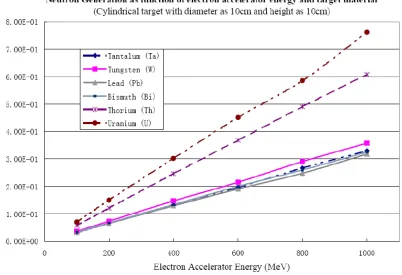
Figure 5: Target Material Neutron Production Efficiency Results [10]
The results in Figure 5 provide two important results. The first conclusion drawn
from the figure is uranium has a much higher neutron conversion efficiency than any of
the other target material candidates analyzed in the study. The second conclusion
exhibited in the figure is there was a fairly linear correlation between the incoming
electron beam’s energy and the neutron conversion rate within the range of 50-1000MeV.
In the analysis performed by Yodersmith, the electron ADS design used a Tungsten
target. Tungsten was chosen as the ADS target material because it had the second highest
neutron production efficiency after uranium. Uranium was not used in the study because
of concerns that the byproducts of the neutron production reactions would inhibit the
transmutation effectiveness of the electron ADS. During the neutron production within
uranium, some capture reactions would occur producing the same TRUs the ADS was
no production of TRUs within the system. However, in the present study, the TRU
production within a uranium target was considered along with the significant increase in
neutron production efficiency possible with uranium when determining which target
material to utilize.
Prior to making a final decision on the target material to use for the ADS design,
the previous work performed in this area by Liu was analyzed.12 Table 2 and Figure 6
show the results from the target material analysis study performed by Liu.
Figure 6: Target Material Neutron Production Efficiency Results12
From Table 2 and Figure 6 the same two trends observed in Figure 5 can be seen.
For all of the materials, a dependence of neutron conversion efficiency on electron beam
energy is shown between 100 and 1000MeV. Once again, uranium has the highest
neutron conversion efficiency of all the material tested. However, one other material,
Thorium, which was not studied by Yodersmith, also had a high neutron conversion
efficiency compared to the rest of the candidate materials.
After reviewing the results of the target material studies presented above, uranium
was shown to be the candidate material most efficient at producing neutrons per incident
electron. Thorium, was the second most efficient candidate target material within the
energy range of 100-1000MeV. Tungsten, however, was the most efficient target
utilized uranium in his ADS design to utilize the highest possible neutron efficiency and
Yodersmith utilized tungsten in an attempt to combined high neutron production
efficiency without any risk of TRU production within the target.
The electron ADS design used in this study will utilize a uranium target. The
target size that maximizes neutron production is another key aspect when designing the
target for use in an ADS. A cylindrical target was used in this study and the data used for
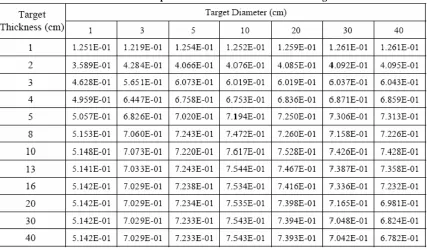
neutron conversion efficiencies from other studies also utilized a cylindrical target. Table
3 shows the results from Liu’s report for various sizes of uranium targets exposed to a
flux of 10,000 1 GeV electrons focused in a 1cm diameter beam for a uranium target.12
Table 3: Neutron Yield per Incident Electron for Various Target Sizes12
The results shown in Table 3 indicate higher neutron yields can be accomplished
by increasing the size of the target up to a point. However, one of the benefits of the
electron ADS over a proton ADS is the possibility of a smaller target; therefore, the target
chosen for this study. After 10-13 cm of thickness, the neutrons escaping the target do
not increase with increasing thickness and in some cases actually decrease. Therefore, a
target thickness of 10 cm is the optimum target size for an electron ADS design. The
maximum neutron flux escaping the outer surface of the target with a thickness of 10 cm
occurred with a diameter of 10 cm. However, the neutron flux for target with diameters 3
and 5 cm are comparable to the 10 cm diameter target. Therefore, if a smaller target is
desired, targets with diameters in the range of 3-5cm would produce neutron fluxes on
the same order as much larger targets. Once the target material has been chosen, the
target size can be more accurately determined.
2.2 ACCELERATOR BEAM
Previous studies have indicated that there is a relationship between the electron
beam energy and the neutron production efficiency of the materials. The correlation
between the neutron conversion efficiency and accelerator beam energy appears to be
linear; however, this does not necessarily mean using a higher accelerator energy is the
best option. Instead, an analysis needed to be performed to determine if more neutrons
could be produced for a given overall accelerator power level by using a higher energy
beam and therefore utilizing the higher neutron conversion efficiency or to use a lower
energy beam with a higher flux of incoming electrons to offset the lower neutron
production efficiency. Therefore, the relationship between the neutron production
efficiency (neutrons/electron) and the electron beam energy (MeV) needed to be
quantified. For a uranium target, the neutrons produced per electron per accelerator
energy, or neutrons produced per unit of accelerator power, increases with higher
value is constant.10 Therefore, anywhere between 300-1000 MeV, for a given accelerator
power, the same number of neutrons are produced by either utilizing a higher beam
current at low energies or the higher conversion ratio at high energies. Since, the number
of neutrons produced per electron per accelerator energy is constant for electron
accelerator systems between the energies of 300-1000MeV other factors besides neutron
production must be investigated to determine the optimum accelerator energy for use in a
transmutation facility.
A related factor of interest in determining the accelerator beam energy is the
technical feasibility of the selected beam energy. The presence of facilities with
experience for specific electron accelerator beam energies needs to be verified. A list of
some of the high energy electron accelerators operating around the world is given in
Table 4.
Table 4: High Energy Electron Accelerators
Accelerator Location Electron Energy Range (Mev)
ELSA13 Germany 500-3500
Bates Linear Accelerator14 USA 300-1100
CEBAF15 USA Up to 6000
MAMI16 Germany Up to 1508
From Table 4 it is clear electron accelerators with energies up to and beyond
1,000MeV have been built and operated. Currently there are not many electron
accelerators operating at 1,000MeV. As deployment of an ADS is considered to be
decades in the future7, it is assumed electron accelerators with energies up to 1,000MeV
The majority of this thesis deals with a study on the effect of loading patterns on
the keff and peaking within a single target fast flux electron ADS. Use of multiple targets
within the electron ADS in an attempt to achieve more acceptable power peaking factors
within the reactor core is also investigated. Therefore, the ability to provide an electron
beam from the accelerator facility to multiple targets must be considered. There are two
possible methods for creating multiple electron beams from the accelerator facility for
use within the ADS. The first method would be to utilize multiple accelerators. The use
of multiple accelerators is feasible; however, the second method where the beam from
one accelerator is split into multiple beams would be a more capital cost efficient method.
Accelerator beam splitting is performed at many currently operating accelerators used for
experiments. For example, CEBAF the accelerator with the highest energy electron beam
listed in Table 4 can split the beam into two or three separate experiment halls with the
beam current being divided among the targets.17
2.3 NEUTRON SPECTRUM
The third component in an ADS is the subcritical core which multiplies the
neutrons from the target. The multiplied neutron flux is used to transmute the waste
within the reactor core. The first major decision for the design of the subcritical core for
an ADS is whether to use a fast or thermal neutron flux within the core. 90Tc and 129I, the
fission products of most concern in SNF waste cannot be effectively transmuted within a
fast reactor flux. Therefore, if transmutation of these fission products is a high priority, a
thermal reactor design must be used for the ADS subcritical core. However, if
transmutation of the TRUs in SNF are the major goal of the ADS, then the cross-sections
neutron capture for TRUs does not easily result in stable isotopes. Therefore, the goal of
the ADS is to fission the TRUs. To ensure neutron economy within the ADS, the capture
to fission ratio of the TRUs becomes the most important factor. Figure 7-Figure 19 show
the capture and fission cross-sections of 237Np, 238Pu, 239Pu, 240Pu, 241Pu, 242Pu, 241Am,
242m
Am, 243Am, 244Cm, 245Cm, 246Cm, and 247Cm for energies up to 20 MeV. These plots
were produced using ENDFPLOT II18 and the MCNP library. The cross-sections of other
TRUs were also studied but only the TRUs that were eventually used in the final design
are provided here.
Figure 8: Pu-238 Cross Sections (Fission-Brown; Capture-Green)
Figure 10: Pu-240 Cross Sections (Fission-Brown; Capture-Green)
Figure 12: Pu-242 Cross Sections (Fission-Brown; Capture-Green)
Figure 14: Am-242m Cross Sections (Fission-Brown; Capture-Green)
Figure 16: Cm-244 Cross Sections (Fission-Brown; Capture-Green)
Figure 18: Cm-246 Cross Sections (Fission-Brown; Capture-Green)
Figure 7-Figure 19 show for all TRUs used in the final design the fission
cross-section is higher than the capture cross-cross-section above ~0.5-0.7MeV. Five of the TRUs
shown above have higher fission than capture cross-sections across the entire energy
range, except possibly at some resonance locations. Therefore, when considering the
higher fission to capture cross-section of the TRUs as the main design criteria, a fast
reactor flux is the best design for the sub-critical core when the transmutation of the
TRUs present in SNF is the primary concern.
2.4 FUEL MATERIALS
All LWR power reactors currently operating in the US utilize UO2 as the fuel
form. UO2 is a solid ceramic with a large experience base for reactor operations and
design. However, the fuel for an ADS will not utilize uranium because more waste
would be produced during operations. Operating and designing reactors using TRU fuel
does not have a large experience base with any particular fuel form; therefore, the fuel
form used for an ADS design is more open-ended than choosing a fuel form for a
traditional uranium fueled power reactor. ADS fuel can be in either a solid or liquid
form.
The use of liquid fuel in nuclear reactors has been briefly studied at various times.
However, most of these experiments have dealt with thermal neutron spectra. Therefore,
the experience base for a fast spectrum liquid fuel reactor is very limited when compared
to solid fuel reactors. A possible benefit of using a liquid fueled reactor for an ADS is
online reprocessing of the fuel. If online reprocessing of the fuel is possible, then there
would not be a need to fluctuate the accelerator beam current to maintain keff since the
for criticality. The most prominent liquid fueled reactor experiment in the US was the
Molten Salt Reactor (MSR) operated at Oak Ridge National Laboratory between 1950
and 1976. During the MSR experiment, many problems associated with a molten salt
reactor were identified including corrosion/noble metal plating, reactions between the
molten salt and water working fluid of a Rankine power cycle, etc. However, some of
these problems may be alleviated by technologies developed in the 30+ years since the
MSR was shutdown.19 Even with these new technologies for a molten salt reactor, liquid
fueled reactors are generally more likely to be considered for use in a thermal spectrum
ADS.4
Compared to a liquid fueled thermal reactor design, almost all designs of fast
reactors have utilized a solid fuel form. The use of solid fuels is considered more
compatible with a fast spectrum reactor. The use of solid fuels also has a much larger
experience base and has been under continuous research and development throughout the
world in fast reactors. Metal alloy fuel is also compatible with the pyrochemical
reprocessing technique developed by Argonne National Laboratory for use in the
proposed ADS fuel cycle.4 Table 5 provides a comparison of using either a solid or
liquid fuel form in the fast spectrum ADS design.
Table 5: Comparison of Solid and Liquid Fuel Forms for a Fast Spectrum ADS20
Solid Fuel Form Liquid Fuel Form
Compatible with pyrochemical reprocessing technique
Possibility of online reprocessing capability
Suitable for fast spectrum ADS Typically used in thermal spectra
Larger experience base Almost non-existent experience base for fast spectrum reactors
Given the information given above and summarized in Table 5, the design for a
fast spectrum ADS would most likely utilize a solid fuel form. Some of the possible
solid fuel types are metals fuels (usually alloys), nitride pellets, dispersion fuels, or
TRISO coated fuel particles. Table 6 lists the advantages and disadvantages possible by
using a metal alloy fuel in an ADS environment.
Table 6: Advantages and Disadvantages of Metal Alloy Fuels20
Advantages Disadvantages
High fissile atom density Little to no experience with non-fertile compositions
High thermal conductivity Fuel-cladding chemical interaction (or interdiffusion)
Low heat capacity Loss of volatile americium during fabrication
High thermal expansion Limitations to fuel temperature to avoid melting (not a restrictive criterion in
EBR-II experience) Potentially simple fabrication
Established experience base for U-bearing fuels (EBR-II, IFR)
From Table 6 there are currently four identifiable disadvantages to using a metal
alloy fuel for the ADS design. The first disadvantage listed is the low experience base
for metal alloy fuels with non-fertile compositions. However, from Table 7-Table 9 we
also see none of the four candidate fuel types have a large experience base for non-fertile
fuels. TRISO coated particles have the largest experience base but it is still not large
enough to place it ahead of the other candidates. One of the other disadvantages listed
for metal alloy fuel is the limitations on fuel temperatures required to avoid melting.
reactor, the EBR-II.20 One concern with the limit on fuel temperatures is the higher
peaking factors in an ADS core than other core designs such as the EBR-II.
Most of the advantages for a metal alloy fuel type concern safety margins within a
reactor. However, the metal alloy fuel type is the only fuel type with a relatively simple
fabrication process developed. This is a large benefit over the other possible fuel types.
Since the goal of an ADS design is to fit into the fuel cycle such that nuclear power
maintains its economic viability, low cost of fuel fabrication is essential. In a solid fueled
ADS system, the fuel will most likely be reprocessed several times to be returned to the
reactor; therefore, cheap fabrication techniques are highly beneficial. Table 7 lists the
advantages and disadvantages of nitride pellet fuel.
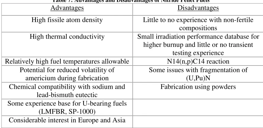
Table 7: Advantages and Disadvantages of Nitride Pellet Fuels20
Advantages Disadvantages
High fissile atom density Little to no experience with non-fertile compositions
High thermal conductivity Small irradiation performance database for higher burnup and little or no transient
testing experience Relatively high fuel temperatures allowable N14(n,p)C14 reaction
Potential for reduced volatility of americium during fabrication
Some issues with fragmentation of (U,Pu)N
Chemical compatibility with sodium and lead-bismuth eutectic
Fabrication using powders
Some experience base for U-bearing fuels (LMFBR, SP-1000)
Considerable interest in Europe and Asia
In Table 7, the disadvantage of a low level of experience with non-fertile
compositions of the fuel type is listed again. However, unlike metal alloy fuels, nitride
fuel pellets require fabrication using powders which is a disadvantage. Nitride fuel also
core. The main benefit of nitride fuels over metal alloys is the possibility of higher fuel
temperatures. When considering the disadvantages versus the advantages of using a
nitride pellet fuel form within the ADS design, metal alloy fuels were considered the
better choice. However, as shown in Table 8, using a dispersion fuel may provide
benefits over metal alloy fuels not provided by nitride pellets.
Table 8: Advantages and Disadvantages of Dispersion Fuels20
Advantages Disadvantages
High-burnup potential Little to no experience with non-fertile compositions or fuel particles of the type
proposed High thermal conductivity Low fissile density Relatively high fuel temperatures allowable
for nitride
N14(n,p)C14 reaction for nitride
Potential for reduced volatility of americium during fabrication of nitride
Possible temperature limitations for metallic dispersion
Chemical compatibility with sodium Chemical compatibility with lead-bismuth eutectic for some matrix metals Some experience base for U-bearing fuels Fabrication using powders
Table 8 shows dispersion fuels have many of the same limitation as metal alloy
fuels. The presence of 14N(n,p)14C reactions promotes the use of metal dispersion fuels
over nitride dispersion fuels. Therefore, the temperature limits of the fuel are similar
between the metal dispersion and metal alloy fuels. Metal dispersion fuels have the
disadvantage of fabrication requiring powders; however, it has a major advantage over
metal alloy fuels. The primary advantage of metal dispersion fuels over metal alloy fuels
is the possibility of higher burnup limits. High burnup limits are important in an ADS
design. With higher burnup limits the waste can be transmuted in a given cycle of the
ADS to a higher degree. The result is longer cycles for the ADS which reduce the
advantage present in metal alloy fuels. In order to make the decision between using a
metal alloy or metal dispersion fuel in the ADS a more thorough examination of the
burnup differences in the two fuel types must be made. However, before examining this
factor, a comparison with TRISO coated fuel particles is made. The aspects of using
TRISO coated fuel particles is listed in Table 9.
Table 9: Advantages and Disadvantages of TRISO Coated Fuels20
Advantages Disadvantages
High-burnup potential Small experience base with non-fertile compositions
High fuel temperatures allowable for nitride
Reliability of fuel particles in fast spectrum uncertain, at best
Good experience base for U-bearing fuels, and a small favorable experience base for a
non-fertile oxide (PuO2)
Impact of multiple valence states of TRU oxides on fabrication of fuel kernels
Some interest in non-fertile compositions for Pu disposition in Russia
Fabrication using powders
From Table 9, the TRISO coated particles have some different advantages and
disadvantages from the metal alloy or dispersion fuel types. TRISO coated fuel particles
do have high burnup limits as a main benefit. However, the major disadvantage of the
TRISO fuel particles is the fabrication of the fuel kernels when using TRUs. The
fabrication of TRISO fuel also relies on powders and these two disadvantages have a
large impact when designing an ADS system with TRU fuel where multiple fabrications
may be required. Fabrication of TRISO fuel is already a major technical hurdle and the
addition of complication form TRU oxides during the process merely increases the
difficulty. Since the fabrication process for TRISO particles appears to be the main
technical ‘show-stopper’ and multiple fabrications will be required in the ADS fuel cycle,
Therefore, the fuel type used in the fast spectrum ADS design is narrowed down to metal
alloy and metal dispersion fuels.
The major benefit of metal dispersion fuels over metal alloy fuels listed above is
the possibility of higher burnup limits which may overcome the disadvantage in the
fabrication process of metal dispersion fuels. Experimental data concerning the burnup
limits of metal alloy fuels versus metal dispersion fuels is practically non-existent.
However, some simulation data does exist which compares the burnup capabilities of
dispersion and ally fuels. Before analyzing the burnup data for the two fuel types, a note
regarding the helium generation during the transmutation of 241Am must be made.
During the transmutation of 241Am, the americium can capture a neutron and become
242
Cm after beta decay. The 242Cm then alpha decays to 238Pu, thereby producing helium
within the fuel structure. The effect of the He generation within metal dispersion fuels
has a much greater impact than He generation in metal alloy fuels. The values of
cladding strain as a function of burnup are nearly identical in metal alloy fuel with and
without He generation effects. However, in dispersion fuel the cladding strain at a
burnup level of 30a/o is 2.85% without He generation effects and 3.3% with He
generation effects. Comparing these numbers with the 3.01% cladding strain in metal
alloy fuel with 30a/o burnup reveals that the burnup limit of the dispersion fuel may be
lower or higher than alloy fuel depending on the He generation effects.21 If metal
dispersion fuels cannot provide higher burnup levels than metal alloy fuel, the fabrication
advantage of the metal alloy fuel takes precedence. 241Am accounts for over 6% of the
TRUs present by mass in the ADS fuel. Therefore, the He generation effect cannot be
2.5 CORE COOLANT
The primary candidates for coolant in a fast reactor are lead, lead-bismuth
eutectic, sodium, and helium. The first three choices are liquid metals while helium
would be a gas cooled reactor. To decide which coolant option to utilize in the reactor
design, the benefits and disadvantages of each option were analyzed. In a fast reactor, the
coolant should have a small capture cross section, high scattering cross section, low
energy transfer per collision to reduce moderation, and a larger single phase operating
range.22 All of the above coolant choices meet these requirements to varying degrees and
exhibit other beneficial qualities.
The most unique coolant choice listed above is helium which would result in a gas
cooled reactor design for the electron ADS. The design of gas cooled reactors has been
promoted for various reasons; however, the progress in designing a helium cooled reactor
is much farther behind than either a lead, lead alloy, or sodium cooled reactor. Lead and
sodium cooled reactors have been operated before, particularly in the United States and
Russia. One possible benefit of using an electron ADS over a proton ADS is that
electron accelerators are currently more developed, and therefore more stable, which is
highly beneficial in a reactor environment. Therefore, the electron ADS design should
attempt to utilize characteristics that are as far along in development as possible to allow
for the earliest possible deployment date of the system. When considering this, the use of
helium as a coolant within the electron ADS design is not considered beneficial due to its
low level of experience and knowledge base around the world when compared with the
Lead-bismuth eutectic (LBE) is a lead bismuth alloy with the proportion of lead to
bismuth which has the lowest melting point of any combination of the two components.
For a lead-bismuth alloy the eutectic occurs with 55.5w/o bismuth and 45.5w/o lead.
Lead has a melting point of 327.4oC and bismuth‘s melting point is 271oC; however, LBE
has a much lower melting point at 123.5oC. The low melting point of LBE is beneficial
in a fast reactor design which utilizes high operating temperatures but will also
experience lower temperatures during shutdown. A low melting temperature decreases
the need for special equipment for the coolant to be kept in or changed into the liquid
phase at shutdown temperatures. The boiling temperature of LBE is very high at 1670oC
satisfying the large single phase operating range requirement for the coolant. Having a
high boiling temperature reduces the need to consider reactivity effects from voids in the
coolant.22
LBE is composed of lead and bismuth which are both elements with high atomic
numbers. The heavy atoms LBE is composed of result in a low energy transfer per
collision between the coolant and neutrons within the core. The low energy transfer rate
results in a harder energy spectrum within the ADS which utilizes the higher fission to
capture cross section ratios of the TRUs at higher energies. LBE also has a low capture
cross section which is important in an electron ADS with its lower neutron productions
efficiency in the target when compared with the proton ADS. LBE has other benefits
such as a low volume change up solidification, a high level of gamma shielding and
fission product retention in case of core accidents.7
The neutronics performance and operating temperature range of LBE suggest it
disadvantages to using LBE within the design. LBE is highly corrosive and can dissolve
steels that may be utilized in the core construction. LBE’s operating experience base in
the United States is non-existent. However, in Russia there is a much larger experience
base with lead and LBE coolants. In Russia, there has also been progress in developing a
method to control the corrosiveness of LBE as a coolant. Oxygen is introduced to the
system allowing for a protective oxide coat to develop on the core structures. The
process is still relatively new and very delicate at this point in its development.
Therefore, the availability of the method in the near future for an ADS deployment
should not be assumed.7
The second disadvantage of using LBE as the coolant in an ADS design is the
production of radioactive 210Po within the coolant when exposed to a neutron flux. The
209
Bi within the LBE coolant becomes 210Bi after a neutron capture. 210Bi then captures a
neutron and after a beta emission becomes 210Po, which emits a 5.1MeV alpha particles
with a half-life of 138.3 days. 210Po can be especially harmful during a leakage accident
because it disperses quickly in a given volume of space.22
The coolant choice that can be most directly compared to using LBE is using a
pure lead coolant. Using lead as the coolant would maintain some of the benefits of LBE
such as the hard neutron spectrum and beneficial cross sections allowing for low neutron
leakages within the core while still minimizing any softening of the neutron spectrum.
Using a pure lead coolant also reduces the activation levels of the coolant when compared
with LBE. In lead coolant 208Pb can capture a neutron becoming 209Pb which beta decays
to 209Bi which as shown above can produce 210Po. However, the level of activation in a
lead coolant is able to maintain the beneficial neutronics characteristics of LBE without
having the large activation issue associated with LBE.22
Using LBE as a coolant does have advantages over using lead. The melting point
of pure lead as shown above is 327.4oC. The high melting point of lead posses problems
with maintaining the coolant in a liquid phase whenever necessary and would therefore
require a more elaborate design to control the temperature of the coolant during
shutdown. The corrosion problems that exist for LBE and pure lead are also more
pronounced at higher temperatures. A lead coolant would have to be maintained at these
higher temperatures more often due to its higher melting temperature, which would
further promote the corrosion of core structures exposed to the coolant. The higher
melting temperature of lead makes it a less attractive coolant option for the ADS design
than LBE. An ADS will be a first time endeavor and uncertainties such as corrosion
problems would need to be minimized. Whereas the activation of the coolant is a
measurable affect that can be anticipated in the design.
The final coolant option, sodium, has the ability to overcome many of the
disadvantages of using LBE, but has numerous disadvantages of its own. Sodium does
emit gammas after neutron activation of 23Na; however, the half life of 24Na is 15hrs
meaning the post operational concern of dealing with activated coolant is almost non
existent. For comparison, calculations determining the cooling down time required for
the three coolant types mentioned above in order for the used coolant to be considered
acceptable for industrial purposes by the IAEA can be analyzed. For pure sodium
coolant the cooling time required is about 7yrs and sodium coolant with activated


![Figure 5: Target Material Neutron Production Efficiency Results [10]](https://thumb-us.123doks.com/thumbv2/123dok_us/1745190.1223466/28.612.97.519.75.332/figure-target-material-neutron-production-efficiency-results.webp)