Scholarship@Western
Scholarship@Western
Electronic Thesis and Dissertation Repository
4-20-2012 12:00 AM
Assessment of Wear in Total Knee Arthroplasty Using Advanced
Assessment of Wear in Total Knee Arthroplasty Using Advanced
Radiographic Techniques
Radiographic Techniques
Matthew G. Teeter
The University of Western Ontario
Supervisor
David W Holdsworth
The University of Western Ontario
Graduate Program in Medical Biophysics
A thesis submitted in partial fulfillment of the requirements for the degree in Doctor of Philosophy
© Matthew G. Teeter 2012
Follow this and additional works at: https://ir.lib.uwo.ca/etd
Part of the Medical Biophysics Commons
Recommended Citation Recommended Citation
Teeter, Matthew G., "Assessment of Wear in Total Knee Arthroplasty Using Advanced Radiographic Techniques" (2012). Electronic Thesis and Dissertation Repository. 472.
https://ir.lib.uwo.ca/etd/472
This Dissertation/Thesis is brought to you for free and open access by Scholarship@Western. It has been accepted for inclusion in Electronic Thesis and Dissertation Repository by an authorized administrator of
ASSESSMENT OF WEAR IN TOTAL KNEE ARTHROPLASTY USING ADVANCED RADIOGRAPHIC TECHNIQUES
Spine title: Imaging of Wear in Total Knee Arthroplasty
Thesis format: Integrated-Article
by
Matthew G. Teeter
Graduate Program in Medical Biophysics
A thesis submitted in partial fulfillment of the requirements for the degree of
Doctor of Philosophy
The School of Graduate and Postdoctoral Studies The University of Western Ontario
London, Ontario, Canada
ii
THE UNIVERSITY OF WESTERN ONTARIO
SCHOOL OF GRADUATE AND POSTDOCTORAL STUDIES
CERTIFICATE OF EXAMINATION
Joint-Supervisor
______________________________ David Holdsworth, Ph.D.
Co-Supervisor
______________________________ Douglas Naudie, M.D., F.R.C.S.C.
Supervisory Committee
______________________________ Trevor Birmingham, Ph.D.
______________________________ Robert Bourne, M.D., F.R.C.S.C.
Examiners
______________________________ Michael Dunbar, M.D., Ph.D., F.R.C.S.C.
______________________________ Cynthia Dunning, Ph.D., P.Eng.
______________________________ Maria Drangova, Ph.D.
______________________________ Thomas Jenkyn, Ph.D., P.Eng.
The thesis by
Matthew G. Teeter
entitled:
Assessment of Wear in Total Knee Arthroplasty
Using Advanced Radiographic Techniques
is accepted in partial fulfilment of the requirements for the degree of
Doctor of Philosophy
iii
Abstract
Total knee arthroplasty (TKA) has become the gold standard approach for treating
advanced osteoarthritis of the knee. Although the surgery continues to be very successful
at relieving pain and restoring joint function, its longevity is challenged by wear and
loosening of the implant components. This requires the patient to undergo a revision
surgery to replace the implant, a much more challenging operation than primary
arthroplasty. Wear of the polyethylene tibial inserts from TKA is assessed in vitro using
mechanical wear simulator testing and by examining failed implants retrieved from
patients during revision surgery, as well as with direct in vivo measurements. Current in
vitro measurement tools provide only a global estimate of wear (failing to describe
whether the wear has occurred on the articulating or backside surfaces, or stabilizing
post), or are qualitative measurements, or lack resolution. Current in vivo measurement
techniques are performed statically or quasi-statically, leading to the potential for an
underestimation of wear volume as the contact area of the implant components change
throughout flexion. The purpose of this thesis was to describe, validate, and utilize new
advanced imaging techniques to measure TKA implant wear for both in vitro and in vivo
applications. Micro-computed tomography (micro-CT), a non-destructive, high resolution
imaging technique was utilized to provide detailed images of the geometry of tibial
inserts used in wear simulator trials or retrieved from patients, and create surface
deviation maps to accurately quantify wear. Ways to create an unworn reference
geometry, for use in comparing to a worn retrieved tibial insert when the pre-wear
geometry is unknown, were evaluated and a best practice approach was determined.
iv
during revision surgery, which were found to be well functioning with a yearly wear rate
equivalent to other contemporary implant designs. Finally, a pilot study to evaluate the
use of dynamic single-plane flat panel digital radiography for use in measuring TKA
implant wear in vivo was conducted. The system was determined to have a measurement
accuracy and precision sufficient to begin a pilot clinical study with patients.
Keywords: Total knee arthroplasty, micro-computed tomography, dynamic single-plane
flat panel radiography, polyethylene wear, wear assessment, surface geometry, retrieval
v
Co-Authorship
The following thesis contains manuscripts accepted for publication within
scientific journals. Chapter 2 is an original manuscript that has been published in the
journal Clinical Orthopaedics and Related Research, entitled “Quantification of
Volumetric Wear in Polyethylene Tibial Inserts Using Micro-Computed Tomography.”
The manuscript is co-authored by Matthew G. Teeter, Douglas D.R. Naudie, David D.
McErlain, Jan-Mels Brandt, Xunhua Yuan, Steven J. MacDonald, and David W.
Holdsworth. In my role as a PhD candidate, I participated in designing the study,
performed the micro-CT scans and reconstruction, performed the gravimetric analysis,
analyzed all data, performed the statistical analysis, and wrote the manuscript text. David
McErlain and Jan-Mels Brandt aided in the acquisition of the data and provided editorial
input. Xunhua Yuan and Steven MacDonald advised on study design, interpretation of
the data, and provided editorial input. Douglas Naudie and David Holdsworth, as the
candidate’s supervisors, designed the study, reviewed the results, gave editorial
assistance and provided mentorship.
Chapter 3 consists of three original manuscripts. The first has been published in
the Journal of Arthroplasty, entitled “Determination of Reference Geometry for Tibial
Insert Wear Analysis.” The manuscript is co-authored by Matthew G. Teeter, Douglas
D.R. Naudie, Jaques S. Milner, and David W. Holdsworth. In my role as a PhD
candidate, I participated in designing the study, performed the micro-CT scans and
reconstruction, performed the gravimetric analysis, analyzed all data, performed the
statistical analysis, and wrote the manuscript text. Jaques Milner developed a program
vi
Holdsworth, as the candidate’s supervisors, designed the study, reviewed the results, gave
editorial assistance and provided mentorship. The second paper is in press with the
journal Clinical Orthopaedics and Related Research, entitled “How Do CAD Models
Compare With Reverse Engineered Manufactured Components for Use in Wear
Analysis?” The manuscript is co-authored by Matthew G. Teeter, Douglas D.R. Naudie,
Robert B. Bourne, and David W. Holdsworth. In my role as a PhD candidate, I
participated in designing the study, performed the micro-CT scans and reconstruction,
performed the gravimetric analysis, analyzed all data, performed the statistical analysis,
and wrote the manuscript text. Douglas Naudie, Robert Bourne, and David Holdsworth,
as the candidate’s supervisors, designed the study, reviewed the results, gave editorial
assistance and provided mentorship. The third paper has been submitted to the journal
Knee, entitled “Effects of Reference Geometry on Penetration Measurements in a
Retrieval Study of Tibial Inserts from Total Knee Arthroplasty.” The manuscript is
co-authored by Matthew G. Teeter, Jan-Mels Brandt, Douglas D.R. Naudie, Eric R. Bohm,
Richard W. McCalden, and David W. Holdsworth. In my role as a PhD candidate, I
participated in designing the study, performed the micro-CT scans and reconstruction,
analyzed all data, performed the statistical analysis, and wrote the manuscript text.
Jan-Mels Brandt aided in the acquisition of the data and provided editorial input. Eric Bohm
and Richard McCalden advised on study design, interpretation of the data, and provided
editorial input. Douglas Naudie and David Holdsworth, as the candidate’s supervisors,
designed the study, reviewed the results, gave editorial assistance and provided
vii
Chapter 4 is an original manuscript that is in preparation for submission to the
journal Computer Methods in Biomechanics and Biomedical Engineering, entitled “In
Vivo Dynamic Measurement of Total Knee Replacement Polyethylene Wear: A Phantom
Study.” The manuscript is co-authored by Matthew G. Teeter, Petar Seslija, Kristyn M.
Leitch, Jaques S. Milner, Hristo N. Nikolov, Xunhua Yuan, Douglas D.R. Naudie, and
David W. Holdsworth. In my role as a PhD candidate, I participated in designing the
study, acquired the images, analyzed all data, performed the statistical analysis, and wrote
the manuscript text. Petar Seslija and Kristyn Leitch aided in the acquisition of the data
and provided editorial input. Jaques Milner and Hristo Nikolov contributed key technical
aspects of the methods, and provided editorial input. Xunhua Yuan advised on study
design, interpretation of the data, and provided editorial input. Douglas Naudie and David
Holdsworth, as the candidate’s supervisors, designed the study, reviewed the results, gave
viii
Acknowledgements
There are many individuals who have contributed greatly to the success of this
thesis. I would like to begin by thanking my primary supervisor, Dr. David Holdsworth,
for his mentorship over the course of my graduate education. He is responsible for many
scientific insights, large and small, throughout this thesis, but also for instilling in me a
rigorous method for developing a research project, problem solving, and for
communicating the results of my research through presentations and manuscripts. I would
also like to thank Dr. Douglas Naudie for his many contributions, particularly for
providing much clinical insight into my work, for negotiating support from our industrial
partners, and for providing a sounding board for many different ideas over the years.
The members of my supervisory committee have also provided me with valuable
insight and support. Dr. Robert Bourne is a renowned leader in the field of orthopaedic
surgery, but has always found time for me and maintains an encyclopedic knowledge of
orthopaedics. Dr. Trevor Birmingham has also been very encouraging of my work,
particularly with respect to dynamic radiography, and has allowed me to become
involved with projects outside of my normal field of arthroplasty.
I could never have accomplished the various research projects contained within
this thesis without the support of those within the Holdsworth group in the Imaging
Research Laboratories at Robarts. In particular, I would thank Jaques Milner, who
programmed numerous computer applications for me and was always willing to tackle
whatever challenge I put in front of him, and Hristo Nikolov, who has a fantastic work
ix
precise tolerances. Petar Seslija and Xunhua Yuan are responsible for much of the
dynamic radiography work and likewise helped me tackle a number of challenges with
respect to that project. Chris Norley and Steve Pollmann helped with many issues, large
and small. All members of the Holdsworth group, technicians and students alike,
provided new insights into my research and created an excellent work environment.
I would like to thank the surgeons and research staff at University Hospital for all
of their assistance with various projects over the years, particularly Drs. Steven
MacDonald and Richard McCalden, as well as Kory Charron, Lynsday Somerville, and
Nick Paterson. I have had excellent administrative support throughout my training, for
which I would like to thank Wendy Hough (Medical Biophysics), Darlene Goodine
(Robarts), Penny Campbell and Kathy Stead (LHSC), and Shannon Woodhouse and
Samantha Collings (Joint Motion Program). I would also like to thank all other
co-authors of my publications for their assistance, including Jan Brandt, Eric Bohm, and
Kristyn Leitch.
I would like to acknowledge the financial support I have received, provided by
The University of Western Ontario (Schulich Graduate Scholarship), the Ontario
Graduate Scholarship program, and the Canadian Institutes of Health Research via the
Frederick Banting and Charles Best Canada Graduate Scholarships (both master’s and
doctoral) and the Joint Motion Program.
Finally, I would of course like to thank my family and friends for all of their
support over the years. This includes my parents Valerie and Bill, my brother Jim, and
x
John Runciman provided me with excellent research opportunities during my
undergraduate training at the University of Guelph, and now serve as both friends and
collaborators as I complete graduate school at Western. In recent years my fellow trainees
of the Joint Motion Program have provided me with enjoyable times outside of the lab as
well as with new collaborative ideas, particularly the “wear team.” I will be forever
xi
Table of Contents
Abstract ... iii
Co-Authorship ... v
Acknowledgements ... viii
Table of Contents ... xi
List of Tables ... xiv
List of Figures ... xv
List of Appendices ... xviii
List of Abbreviations ... xix
Chapter 1 Introduction ... 1
1.1 Knee Arthroplasty ... 1
1.1.1 Evolution of Total Knee Arthroplasty Components ... 3
1.1.2 Polyethylene Wear ... 5
1.1.3 Modes of Damage, Types of Wear, and Creep ... 7
1.1.4 Osteolysis and Implant Failure ... 9
1.2 In Vitro Measurement of Polyethylene Wear ... 10
1.2.1 Gravimetric Analysis ... 11
1.2.2 Visual Inspection and Damage Scoring ... 12
1.2.3 Digital Photogrammetry... 14
1.2.4 Coordinate Measuring Machines ... 14
1.2.5 Laser Scanning ... 15
1.3 In Vivo Measurement of Polyethylene Wear ... 17
1.3.1 Radiography ... 18
1.3.2 Radiostereometric Analysis ... 18
1.4 Description of Imaging Modalities for In Vitro and In Vivo Measurement of Polyethylene Wear ... 20
1.4.1 Micro-Computed Tomography ... 20
1.4.2 Single-Plane Radiography ... 22
1.5 Thesis Objectives ... 25
1.6 Thesis Organization ... 27
1.7 References ... 27
Chapter 2
In Vitro
Quantification of Wear in Tibial Inserts Using
Micro-Computed Tomography ...37
2.1 Introduction ... 37
2.2 Methods ... 38
2.3 Results ... 43
2.4 Discussion... 45
2.5 References ... 49
Chapter 3 Optimization and Application of Reference Geometries for
Measuring Wear in Retrieval Studies of Polyethylene Tibial Inserts ....52
xii
3.1.1 Construction of Reference Geometries from Averaged Inserts ... 53
3.1.2 Construction of Reference Geometries from CAD Models ... 54
3.1.3 Assessment of Reference Geometries in a Retrieval Study ... 54
3.2 Methods ... 56
3.2.1 Construction of Reference Geometries from Averaged Inserts ... 58
3.2.2 Construction of Reference Geometries from CAD Models ... 61
3.2.3 Assessment of Reference Geometries in a Retrieval Study ... 65
3.3 Results ... 69
3.3.1 Construction of Reference Geometries from Averaged Inserts ... 69
3.3.2 Construction of Reference Geometries from CAD Models ... 75
3.3.3 Assessment of Reference Geometries in a Retrieval Study ... 79
3.4 Discussion... 82
3.4.1 Construction of Reference Geometries from Averaged Inserts ... 82
3.4.2 Construction of Reference Geometries from CAD Models ... 85
3.4.3 Assessment of Reference Geometries in a Retrieval Study ... 90
3.5 References ... 95
Chapter 4
In Vivo
Dynamic Measurement of Polyethylene Wear in
Total Knee Replacement: A Phantom Study ...101
4.1 Introduction ... 101
4.2 Methods ... 103
4.2.1 Calculation of Implant Penetration ... 103
4.2.2 Dynamic Knee Replacement Phantom ... 106
4.2.3 Imaging Setup and Acquisition ... 107
4.2.4 Assessment of Measurement Bias ... 110
4.2.5 Assessment of Sensitivity to Volume Change ... 113
4.3 Results ... 116
4.3.1 Assessment of Wear Measurement Bias ... 116
4.3.2 Assessment of Sensitivity to Volume Change ... 116
4.3 Discussion... 122
4.4 References ... 131
Chapter 5 Conclusions and Future Directions ...135
5.1 Summary of Results ... 135
5.2 Related Future Directions ... 140
5.1.1 Wear Simulator Studies ... 141
5.1.2 Implant Retrieval Studies ... 142
5.1.3 Reverse Engineering of Component Geometries ... 145
5.1.4 Dynamic Wear Measurement ... 146
5.1.5 Computer Modeling and Finite Element Analysis... 148
5.3 References ... 150
Appendix A Additional Analyses from the Dynamic Wear
Measurements ...153
A.1 Effect of Voxel Size on Wear Volume and Run Time ... 154
A.2 Effect of In-plane RMS Error on Wear Volume ... 155
xiii
xiv
List of Tables
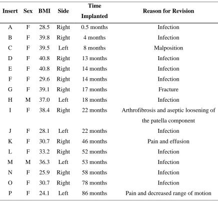
Table 3.1: Patient information for the retrieved components. Insert corresponds to the deviation maps in Figures 3.10 and 3.11. ... 66
Table 3.2: Individual insert 3D surface deviation from the reference geometries
(Absolute Mean ± Standard Deviation in µm). ... 69
Table 3.3: Results of the statistical comparisons between reference variability for the three reference geometries and scan variability, manufacturing variability, and wear rate.
... 70
Table 3.4: Mean ± SD of micro-CT, gravimetric, and CAD volumes of the tibial inserts.
... 75
Table 3.5. Mean 3D deviations between geometries within regions of the articular
surface in which wear is typically found. ... 76
Table 4.1: Wear volume and maximum wear depth in the manufactured unworn, milled unworn, and milled worn tibial inserts. ... 115
xv
List of Figures
Figure 1.1: Example of a typical total knee replacement implant. ... 4
Figure 1.2: A polyethylene tibial insert that has been retrieved from a patient during revision surgery, demonstrating severe wear. ... 6
Figure 1.3: The AMTI six station mechanical knee wear simulator located at University Hospital, London Health Sciences Centre. ... 11
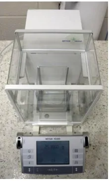
Figure 1.4: A typical high-precision scale used for gravimetric analysis. ... 12
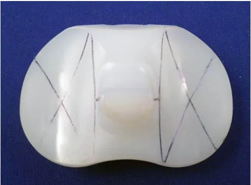
Figure 1.5: A retrieved tibial insert marked for damage scoring. ... 13
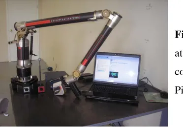
Figure 1.6: A handheld laser scanner attached to a precision arm and laptop computer. 16
Figure 1.7: The RSA Imaging Suite located in the Robarts Research Institute. ... 19
Figure 1.8: The GE eXplore Vision 120 micro-CT scanner, located in the Preclinical Imaging Research Centre at Robarts Research Institute. ... 21
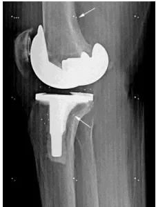
Figure 1.9: Beads (arrows) implanted in a patient’s femur and tibia surrounding a total
knee replacement implant, as part of an RSA examination. ... 23
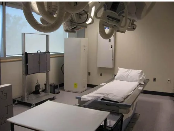
Figure 1.10: The GE Innova 4100 digital flat panel radiography system located at
University Hospital, London Health Sciences Centre. ... 24
Figure 2.1: Photograph of inserts held in foam on the bed of the scanner (A) and a rendered image of the insert in the bed at a double-oblique angle of approximately 10 degrees backward vertically and 3 degrees laterally (B). ... 39
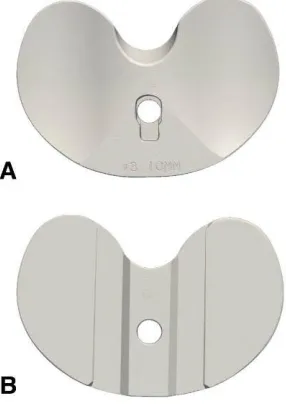
Figure 2.2: 3D rendered volume images of an unworn tibial insert scanned with micro-CT, including the bearing surface (A) and backside (B). ... 41
Figure 2.3: Rendered volume images of a worn tibial insert scanned with micro-CT. ... 41
Figure 2.4: Mean volume of the six unworn inserts (UA through UF) as measured by gravimetric analysis and micro-CT (A) and mean volume of the six worn inserts (WA through WF) as measured by gravimetric analysis and micro-CT (B). ... 44
Figure 2.5: Surface deviation map for one of the six worn inserts versus an unworn insert, for the bearing surfaces (A) and backside (B). ... 45
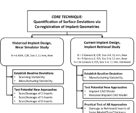
Figure 3.0: Outline of study design for Chapter 3. ... 56
Figure 3.1: 3D rendered image of an unworn polyethylene tibial insert, constructed by averaging three micro-CT scans of the insert. ... 59
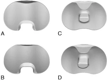
Figure 3.2: 3D geometry of the CR inserts from the CAD model (A) and micro-CT scan (B), and of the PS inserts from the CAD model (C) and micro-CT scan (D). ... 63
xvi
Figure 3.4: Maps of the 3D surface deviations (in µm) between the six individual tibial inserts (inter-insert variability due to the manufacturing process). ... 71
Figure 3.5: Maps of the overall absolute mean 3D surface deviations (in µm) between the three reference geometries and six individual tibial inserts. ... 72
Figure 3.6: Maps of the overall standard deviation of 3D surface deviations (in µm) between the three reference geometries and six individual tibial inserts. ... 73
Figure 3.7: Maps of the overall absolute mean 3D surface deviations (in µm) between the six-insert idealized reference geometry and the worn tibial insert. ... 74
Figure 3.8: Maps of the three-dimensional surface deviations (in microns) for the CR inserts. ... 77
Figure 3.9: Maps of the three-dimensional surface deviations (in microns) for the PS inserts. ... 78
Figure 3.10: Articular surface deviation maps for the retrieved inserts generated using the reverse engineered reference geometry. ... 80
Figure 3.11: Articular surface deviation maps for the retrieved inserts generated using the CAD model reference geometry. ... 81
Figure 4.1: Experimental setup of the anthropomorphic knee phantom with total knee replacement implant, mounted to the robot, ready for imaging with the single plane dynamic radiography system. ... 108
Figure 4.2: Demonstration of the translational correction factors used to initialize the implant geometry registration. ... 112
Figure 4.3: Correlation between the micro-CT measurements and dynamic wear measurements for wear volume (A), lateral maximum wear depth (B), and medial
maximum wear depth (C). ... 119
Figure 4.4: Bland-Altman plots between the micro-CT measurements and dynamic wear measurements for wear volume (A), lateral maximum wear depth (B), and medial
maximum wear depth (C). ... 120
Figure 4.5: Wear maps of the five milled worn tibial inserts. ... 121
Figure 4.6: Intersection frequency map from one acquisition cycle for the most worn milled tibial insert (MWE). ... 122
Figure 5.1: Surface reconstructions from micro-CT of a PEEK disk (A) and pin (B) before pin-on-disk material testing. ... 142
Figure 5.2: Surface deviation maps from micro-CT of a PEEK disk (A) and pin (B) after pin-on-disk material testing. ... 142
Figure 5.3: A planar image taken from a micro-CT scan of a retrieved polyethylene tibial insert, demonstrating subsurface cracking (arrows). ... 143
xvii
Figure 5.5: A highly cross-linked polyethylene acetabular liner, retrieved from a patient after 10 years implantation, and assessed for surface deviations due to wear and creep using micro-CT. ... 144
Figure 5.6: A titanium osteotomy plate (A) scanned with micro-CT to generate a surface geometry (B). ... 145
Figure 5.7: A cobalt-chromium femoral component from a total knee implant (A) scanned with micro-CT, demonstrating streaking artifact characteristic of dense metal objects (B). ... 146
Figure 5.8: A step-up platform instrumented with a force plate (A) will enable the collection of knee joint kinematics, kinetics, and implant wear from patients (B). ... 148
Figure 5.9: For a retrieved tibial insert, a deviation map was constructed (left) and compared to peak stresses during gait (right). ... 149
Figure A.1: Graph demonstrating the effect of voxel size (horizontal axis, in mm) on both wear volume (left vertical axis, in mm3, line in red) and computational run time (right vertical axis, in s, line in blue). ... 154
Figure A.2: 3D renderings of the CT isosurfaces (red) and CAD models (grey) for the femoral component (top) and tibial component (bottom). ... 156
Figure A.3: Deviation map for the femoral component, between the CT isosurface (reference) and the CAD model. ... 157
Figure A.4: Deviation map for the tibial component, between the CT isosurface
xviii
List of Appendices
Appendix A: Additional Analyses from the Dynamic Wear Measurements……..……153
Appendix B: Ethics Approvals……….………..159
xix
List of Abbreviations
2D two-dimensional
3D three-dimensional
CAD computer-aided design/computer-aided drawing
CMM coordinate measuring machine
CR cruciate retaining
CT computed tomography
HU Hounsfield unit
Hz Hertz
MBRSA model-based radiostereometric analysis
Micro-CT micro-computed tomography
mm millimetre
NSAID non-steroidal anti-inflammatory drug
PEEK polyether ether ketone
PMMA polymethylmethacrylate
PS posterior stabilizing
RSA radiostereometric analysis
SD standard deviation
THA total hip arthroplasty
TKA total knee arthroplasty
UKA unicompartmental arthroplasty
Chapter 1
Introduction
1.1 Knee Arthroplasty
Osteoarthritis is an increasingly common progressive disease.1 Worldwide, the
knee is the joint most commonly affected by osteoarthritis, and over time the entire knee
joint can become damaged by the disease.1,2 Symptoms may include pain, stiffness, and
decreased joint function.2 The initial treatment of osteoarthritis is conservative, including
regular exercise and physical therapy, as well as the use of drugs such as acetaminophen,
non-steroidal anti-inflammatories (NSAIDs), and intra-articular injections of
corticosteroids and hyaluronate.1,3,4 Should symptoms persist after these treatments,
surgical intervention is recommended.1,3 For severe osteoarthritis, partial or total knee
replacement (arthroplasty) can be undertaken. Total knee arthroplasty (TKA) is
performed to relieve pain as well as enhance function, range of motion, and joint
stability.5 The indications for TKA surgery are radiographic evidence of knee
osteoarthritis (i.e. joint space narrowing), along with pain and disability not correctable
by non-surgical therapy.1,6
Rates for joint replacement have increased worldwide, with demand expected to
increase substantially due to aging populations.1 In Canada (excluding Quebec), over
recent reporting year of the Canadian Joint Replacement Registry.7 The number of knee
replacements in Canada increased 140% between 1996-97 and 2006-07, with the largest
percent increase in the 45 to 54 year old age group (271% for males, 337% for females).7
TKA has become the gold standard for treatment of end-stage osteoarthritis in the knee,
as it has proven to be both safe and cost-effective.1,5,8 However, TKA is irreversible, and
is thus undertaken only as a last resort following the failure of other, joint-maintaining
therapies.1,3 In addition, adverse outcomes can be associated with TKA, including
mortality, infection, and pulmonary embolism.1,5,9 Age and existing co-morbidities are
the main risk factors for these negative outcomes.1
TKA, as it is known today, was developed in the early 1970’s, following on the
development of the total hip arthroplasty (THA).5,10 For the hip, numerous materials were
experimented with before a metal-on-polyethylene design was settled upon. Since the
inception of TKA, the majority of designs have consisted of a polyethylene tibial insert
sandwiched between metal femoral and tibial components.11 More recently,
unicompartmental knee arthroplasty (UKA) has been developed for patients with
osteoarthritis in only one of the three knee compartments (patellofemoral, lateral
tibiofemoral or medial tibiofemoral).1 Of these, the medial tibiofemoral is the most
common to be replaced.1 Although the 10-year survival rate for UKA is slightly worse
than for TKA, a failed UKA is more easily converted to a TKA than can a failed TKA be
revised.1,12 Therefore, UKA may be a better choice for younger patients who will likely
require revision surgery during their lifetime. In TKA, there is a greater risk of failure
over the age of 70, making patients over the age of 70 the preferred candidates for
TKA.1,8,13,14
As surgical techniques and implant technology have improved, the revision rates
for TKA have declined.1,15 Currently, there are excellent 10-15 year outcomes for
primary TKA.15 As widely successful as TKA is, it remains an imperfect technique for
many patients. Up to 19% of patients report they are unsatisfied with the outcome of their
surgery, with this lack of satisfaction focusing primarily on pain relief and return of
function.16 For surgeons and implant designers, the primary limitation associated with
TKA is wear of the polyethylene component, which can decrease the longevity of the
implant.17-20 Decreased implant longevity is of a particular concern for younger patients,
who are undergoing TKA at an increased rate and are more active than older patients
post-surgery.21 This increased activity places greater stress on the implant, and can
potentially increase the rate of wear.21 Therefore, in an attempt to improve patient
satisfaction and increase implant longevity, there has been a constant evolution in the
design and the materials used in TKA.
1.1.1 Evolution of Total Knee Arthroplasty Components
Devices for knee arthroplasty underwent a number of redesigns until the development of
a bone cement, polymethylmethacrylate (PMMA), which allowed proper fixation.5 Early devices
were of a hinged design, allowing only fixed-axis motion, with limited rotary motions added
later.5 The general TKA prosthesis design used today – involving a polyethylene tibial insert
between a metal femoral component and a metal tibial tray – was developed in the 1970’s.5,10
Since then, these three components as well as the instrumentation used to implant them, have
and materials are now available to patients and surgeons. The overall goals for all TKA designs
are to increase functional performance and wear resistance while maintaining excellent long-term
fixation.15 Metal-on-metal and ceramic-on-polyethylene TKA implants have been developed, but
concerns surrounding the biocompatibility and carcinogenicity of these implant types exist. Due
to these concerns, cobalt-chromium-molybdenum against polyethylene continues to be the most
prevalent design for TKA (Figure 1.1).11
Compared to other alternative bearings, polyethylene has remained the gold
standard for articular surfaces due to its superior wear resistance, biocompatibility, and
fracture toughness.22,23 The major limitation of polyethylene is its susceptibility to
oxidative degradation, which diminishes its mechanical advantages.22,24-26 Oxidation also
increases the formation of wear debris.27 This oxidation has been correlated to the
methods used to sterilize the polyethylene for implantation.22,23 High-energy radiation in Figure 1.1: Example of a typical total knee replacement implant. A:
Cobalt-chromium femoral component. B:
Polyethylene tibial insert. C: Titanium
air results in significant amounts of oxidation, whereas sterilization with ethylene oxide
or gas plasma does not oxidize the components.22,26,28-31
Polyethylene may also be irradiated in order to cross-link its polymers. Highly
cross-linked polyethylene was introduced in the 1990’s in an effort to improve the wear
resistance of implants and is now in widespread use for THA.27,32-34 Wear simulator
studies have also demonstrated reduced wear volumes in tibial inserts manufactured from
highly cross-linked polyethylene in comparison to those manufactured from standard
polyethylene.15,35 Unfortunately, the increased wear resistance seen with highly
cross-linked polyethylene is compromised by a decrease in material fracture toughness.34,36 The
use of highly cross-linked polyethylene in TKA is therefore controversial, yet its
significant clinical successes in THA will likely result in the widespread introduction of
highly cross-linked polyethylene in TKA to minimize wear.18,34,36
1.1.2 Polyethylene Wear
Polyethylene wear is the progressive loss of polyethylene material from the
implant due to mechanical action.18,37 This mechanical contribution to polyethylene wear
occurs in TKA due to the complex articulation of the knee, which includes rolling,
sliding, and rotational motions.18 These motions are enabled by the non-conforming
surfaces of the knee, which experience greater stresses than the hip’s conforming
surfaces.11 Due to these higher contact stresses, damage found in tibial inserts is generally
greater than damage in acetabular liners.11 Polyethylene wear can occur on any part of the
insert surface, including the bearing surface (Figure 1.2), the backside (undersurface) of
volume of polyethylene wear that occurs in vivo is dependent on patient, implant, and
surgical factors.18,21 Severe wear can occur within only a short implantation time due to
the high stress experience by the knee geometry, and can lead to restricted range of
motion, disturbance of knee joint kinematics, and possibly joint instability.11
The primary patient factors related to polyethylene wear are age, weight, and
activity level, as these factors determine the amount and rate of load applied to the
implant.11,18,21,37 Of these, activity level has the greatest effect on the implant and can
vary as much as 45-fold between individuals.18,21 Other patient factors include gait
mechanics, limb alignment, primary versus revision TKA, implant time in situ,
co-morbidities, cultural demands, and knee anthropometrics.21,44 Any patient factor that
increases the magnitude of load applied to the implant will in general decrease the wear
performance of that implant.21
Implant factors include component design, component materials, the bearing
couple, the sterilization process, and the fixation method.18,21,23 These factors relate to the Figure 1.2: A polyethylene tibial insert that has been retrieved from a
generation of particulate debris in addition to wear performance.18 Component design
factors are modularity, locking mechanism, thickness, constraint, and conformity.18,21
Material options include conventional versus highly cross-linked polyethylene, as well as
metallic and ceramic designs.11,21 The materials used are also important for the other
components involved in the bearing couple, as polyethylene may be used in conjunction
with metallic (cobalt-chromium or titanium) and ceramic components.21,37
Surgical factors are also important for minimizing polyethylene wear.18,23 These
include surgical approach, component position, restoration of the mechanical axis,
implant stability, component fixation, soft-tissue laxity and constraint, subluxation,
dislocation, and surgeon experience.18,21,23 It is imperative for the implant to be correctly
aligned along the mechanical axis, as an improperly aligned implant may result in
increased loading forces and early-onset polyethylene wear.18,23 Currently,
computer-assisted surgical methods are being developed in order to reliably achieve correct
alignment.21
1.1.3 Modes of Damage, Types of Wear, and Creep
Although patient, implant, and surgical factors may influence the amount of wear
that occurs in polyethylene tibial inserts, this wear always occurs due to well-defined
mechanisms. Four distinct modes have been proposed to describe how surface damage
and wear debris may be generated in an artificial joint due to mechanical action.17,37 They
are:
Mode 1: Motion between the two primary bearing surfaces, as intended by the
Mode 2: A bearing surface rubbing against a second non-bearing surface.
Mode 3: The two primary surfaces articulating with an abrasive third body
between them.
Mode 4: Two non-bearing surfaces rubbing against each other.
Combinations of these modes may occur simultaneously, or individually.37 The
worst-case scenario would be for modes 2-4 to occur simultaneously, resulting in rapid
failure of the implant.17 Mode 1 is the most common wear mode for normally functioning
TKAs, as this type of motion is necessary for the function of the joint.17,37 The remaining
modes correspond to a malfunctioning implant.17
The four modes create the environment for the fundamental mechanisms of wear
to occur: adhesion, abrasion, and fatigue.17,23 These processes are responsible for both
wear (removal of material) and damage (change in surface appearance).17 Although
surface damage and wear are often found together in implants, removal of material may
occur without any visible surface damage, or a great deal of damage may occur without
any loss of material. Therefore, surface damage alone is not necessarily a good indicator
for the amount of polyethylene wear that has occurred.17
Adhesion (adhesive wear) occurs when two opposing surfaces come into contact
and form a junction.37 If the adhesive force between the two surfaces is stronger than the
intra-molecular forces within the material of the individual surfaces, the weaker of the
apposing surfaces can be minimized by selecting appropriate materials and lubricants,
thereby minimizing adhesive wear.17
Abrasion (abrasive wear) is caused by a hard material being in contact with a
softer material.37 This abrasive wear may occur with two bodies (metal against
polyethylene) or three bodies (extraneous material between the bearing surfaces).23,37
Abrasion in TKA results in gouging of the polyethylene, producing wear debris.37
Abrasive wear is minimized by manufacturing smooth, polished bearing surfaces and
preventing the entrapment of third body particles.17,23
Fatigue (delamination) occurs due to fluctuating stresses within the implant.37 The
fluctuating stresses from repeated loading leads to subsurface failure of the polyethylene,
eventually causing cracks to appear.11,23,37 Large particles of polyethylene debris can then
be produced.37 Fatigue is minimized by using conforming implant designs that minimize
contact stresses, and materials with high toughness and crack resistance.11,17
In addition to wear and surface damage, creep must also be considered. Creep is
time-dependent plastic deformation in response to a constant load.37 If creep is not taken
under consideration during wear analysis, it can lead to a false wear measurement.45
Typically, creep predominates in vivo for the first year of implantation before reaching a
steady state, at which time further deformation is mostly caused by wear.46
1.1.4 Osteolysis and Implant Failure
When high volumes of polyethylene debris are generated due to wear, adverse
concern to surgeons performing TKA as it may lead to non-specific pain, loosening of the
implant and its eventual failure.11,18 Osteolysis is a significant problem for certain TKA
designs and has been identified as the leading cause of implant failure.18,22,39,47-50 The
particulate debris that is created from polyethylene wear enters the surrounding joint
space and stimulates a foreign-body cellular response.18,51,52 Although the exact immune
system reaction leading to osteolysis is unknown, several immune processes have been
identified as participating.22 Of these, the primary response is a non-specific chronic
inflammatory reaction involving macrophages and fibroblasts.11,22 The macrophages
release pro-inflammatory mediators, stimulating bone resorption by osteoclasts.37 The
number of macrophages involved with the reaction can be directly correlated to the size,
shape, volume, and number of particles.11,22 Particles of 0.1 to 10 m are the most
biologically active as they are a size easily phagocytosed by macrophages.22,37 As some
of the particles may be transported to lymph nodes, a dynamic equilibrium can be created
between particle generation and clearance to the lymphatic system.11 When this
equilibrium is upset due to an accumulation of particulate debris, the tissue reaction will
occur.11
1.2
In Vitro
Measurement of Polyethylene Wear
As the design and materials of implants used in TKA have been developed, it has
been necessary to evaluate the wear properties of the implants. Initial in vitro wear
assessments are performed using a mechanical wear simulator (Figure 1.3) that mimics
ensure the accuracy and comparability of the results.53 However, due to the wide range of
potential conditions, forces, and motions that the joint may experience it is difficult for
such testing to truly mimic in vivo conditions.23 Further economic and time constraints
are also generally imposed on wear simulator testing.53 Therefore, evaluation of the
clinical performance of the implant is necessary.36 Analysis of polyethylene tibial inserts
retrieved from patients during revision surgery has provided many valuable insights into
the occurrence of wear in vivo.17 Regardless of whether the implant undergoing analysis
comes from a wear simulator or has been retrieved from a patient, numerous assessment
techniques have been developed to quantify the amount of wear found on the insert.
1.2.1 Gravimetric Analysis
Gravimetric analysis continues to be the gold standard for assessment of
polyethylene wear during wear simulator trials.45 In this method, the insert is weighed
(Figure 1.4) before being placed in the wear simulator, and then again after undergoing a
certain number of wear cycles.54 The difference between the two masses corresponds to
the amount of polyethylene material lost due to wear. Gravimetric analysis is known to Figure 1.3: The AMTI six
station mechanical knee wear
simulator located at University
Hospital, London Health
be highly precise and accurate, and is also advantageous as it directly measures material
loss. Surface damage and creep can occur with polyethylene tibial inserts and may
contribute to inaccurate wear measurements with other assessment methods, as these do
not result in material loss. However, throughout the wear cycles in the simulator the tibial
inserts will absorb the fluid used to lubricate the artificial joint.54 In testing of highly
cross-linked polyethylene, the amount of absorbed fluid may be greater than the material
lost.54 To compensate, a “load-soak” insert must be used.55 This insert is exposed to the
forces of the wear simulator, but not the movement, thereby causing the same amount of
fluid uptake without the loss of material. The mass increase experienced by the load-soak
insert is then subtracted from the mass of the worn insert to compensate for the fluid
uptake, allowing the true material loss to be determined. An additional limitation of
gravimetric analysis is that it provides only a global accounting of material loss, without
localizing the relative loss at various locations on the insert, such as the articular surface
versus the backside surface.45
Figure 1.4: A typical high-precision scale used for
1.2.2 Visual Inspection and Damage Scoring
For tibial inserts retrieved from patients during revision surgery, visual inspection
with damage scoring is a common method of wear assessment.17,46 The scoring system
was first developed by Hood et al. and is considered semi-quantitative as it partially
quantifies the area covered by each damage mode.56,57 In this method, various zones
across the insert surface (Figure 1.5) are assigned a damage mode (e.g. delamination,
pitting, abrasion, etc.), and the locations and extent of the damage are also
determined.17,46,56 An overall damage score is then calculated. 17,46,56 Although this
approach has been widely used, it is not without limitations.17 Damage scoring relies on
observers’ interpretations of wear mechanisms and their extent, thus the approach is not
entirely quantitative.46,57 In addition, a high damage score does not necessarily correlate
with a high volume of wear.17 Much of the damage may be from plastic deformation or
creep that results in little loss of material.17,38
Figure 1.5: A retrieved tibial insert marked for damage
scoring. Each section is then
scored on the severity of
various damage features, such
1.2.3 Digital Photogrammetry
Digital photogrammetry has been used as a fast, straightforward and
“off-the-shelf” method for quantifying polyethylene wear in tibial inserts.38,57
A stereomicroscope
is first used to delineate areas of wear on the articular surfaces, which are then outlined
with a marker. A digital camera is used to take a photograph of the marked tibial insert
along with two reference grids, which are used to quantify lens distortion and enable the
accurate quantification of the worn areas. Manual or automatic image segmentation
(using edge detection methods) can then be performed with commercially available
software to trace the implant areas and quantify the worn surface area. Automatic
segmentation has been found to be more accurate than manual segmentation, with
maximum errors of 0.3-1.9% versus 0.9-3.8%, respectively.57 This corresponds to 6-46
mm2 and is acceptable for retrieval analysis; however, the error is still relatively high for
wear analysis and is a limitation of the technique. Additionally, digital photogrammetry is
a two-dimensional technique and thus underestimates the actual worn area. However, the
method requires no previous knowledge of the unworn component geometry and is much
less expensive than other techniques, thus it can be useful for simple estimations of wear
in retrieval studies.
1.2.4 Coordinate Measuring Machines
Coordinate measuring machines (CMMs) have recently become popular for both
retrieval and wear simulator studies.45,55,58-60 In CMM, a mechanical probe is used to
characterize the dimensions of the tibial insert by collecting data points along the insert
compared to corresponding points on an unworn reference insert, with the difference
between the two taken as deformation due to wear.46,60 In wear simulator studies, each
insert is usually mapped before undergoing simulator testing and thus serves as its own
unworn reference geometry.45,60 For retrieval studies, however, the unworn geometry of
the implant is unknown, thus a different, non-implanted insert or an unworn section of the
retrieved insert are used to provide the reference dimensions.45,46
The primary advantage of CMM is that it directly quantifies and localizes surface
deviations due to wear.45,46 Gravimetric analysis provides only a global accounting of
material loss, and while visual inspection localizes wear, it cannot quantify it.45,46 When
compared to other techniques such as gravimetric analysis, visual inspection, and digital
photogrammetry, CMM is time-consuming and requires more highly specialized
equipment.57,60 CMM has been shown to provide highly accurate measurements, to
within 1-7 µm.45,46,59,61 However, these measurements are taken within grids with spacing
of 500-5000 µm, thus the linear resolution of CMM is much lower than its probe
accuracy.46,59,61 Scratches due to third body wear, which may be only 200 µm wide, are
therefore unlikely to be fully detectable by CMM.61 Third body abrasion is believed by
some researchers to be the principal mode of polyethylene implant wear, with scratches
of only 1-2 µm resulting in a 7 to 15-fold increase in wear.23,61-63 An additional
significant source of wear in tibial inserts is the backside surface.18,41-43,64 CMM can only
measure backside wear indirectly through the use of additional gravimetric measurements
1.2.5 Laser Scanning
Polyethylene wear analysis using laser scanning and laser micrometry was
developed to enable the quantification of small, localized wear features. Laser scanning
has been used with polyethylene acetabular liners, metallic femoral heads, and the
backside of polyethylene tibial inserts.61,64,65 In laser micrometry, the object is held fixed
in front of the laser for scanning, and must be rotated for each additional scan until the
entire surface is obtained. The laser can only scan positive surface features, thus concave
features such as the articular surface of an acetabular cup or certain features of tibial
inserts (including complex locking mechanisms) cannot be directly scanned. To
compensate, a cast of the object must be created in order to turn negative features into
positive features. Once the appropriate geometry is obtained, the worn acetabular cup (or
tibial insert) is co-registered with an unworn version of itself, creating a wear map of the
various features. Although this method can be highly accurate (up to 0.5 µm), other
scanners may only achieve in-plane resolutions of 250 µm.61,65 In addition, laser
micrometry scans require a large amount of equipment, need extensive labour, and result
in the destruction of the liners or inserts. Finally, the inability of the laser to penetrate
recesses in objects may make it inappropriate for wear analysis of complex geometries.
Figure 1.6: A handheld laser scanner attached to a precision arm and laptop
computer. Courtesy Paul Brophy of
In handheld laser scanning (Figure 1.6), as opposed to laser micrometry, the
scanner can does not require a cast of the material. Somewhat similar to CMM, the object
is fixed in a jig and the scanner is moved across its surface. In certain cases, the object
has to be flipped and scanned in a different direction, requiring a “stitching” of multiple
scans. Disadvantages of this technique are that any reflective object first requires a spray
coating to increase the surface opacity (so that the laser does not pass into the object), and
that very small features (e.g. scratches in the case of polyethylene wear) can not be
obtained within the resolution of a standard handheld laser scanner. However, laser
scanning has significant advantages for certain applications, such as acquiring the
geometries of large objects (that might not fit within a micro-CT scanner) or metal
components (which may cause artifacts within CT images, thereby distorting the resulting
surface geometry).
1.3
In Vivo
Measurement of Polyethylene Wear
The ability to measure polyethylene wear as it is occurring in vivo is an important
goal for the clinical wellbeing of the patient and for research into implant design. Due to
the relatively straightforward geometry of the hip joint, a number of radiographic
techniques have been developed and adopted for measuring wear in THA.66 Measurement
of wear in TKA is not as straightforward, however, and no satisfactory method currently
exists.67 Nevertheless, a number of measurement techniques used to study in vivo wear of
1.3.1 Radiography
The simplest method of TKA wear measurement in vivo is the plain film x-ray,
usually taken in the anterior-posterior direction.68 Care must be taken to ensure the
acquisition is performed perpendicular to the knee joint so as not to erroneously change
the gap between the femoral and tibial components.68 As the tibial insert is not usually
visible on the radiograph, wear is assessed by measuring the distance between the metal
femoral and tibial components on both the medial and lateral sides of the joint. As the
thickness of the tibial insert at time of implantation is known, any difference between the
original thickness and the measured thickness can be considered a loss of material due to
wear. This procedure is similar to the examination of joint space narrowing that the
surgeon will perform prior to arthroplasty in order to assess the severity of the joint’s
deterioration. Although this radiographic method has been used for some studies of
polyethylene wear, it is insensitive to smaller changes due to wear and is therefore only
useful to monitor for severe degradation of the implant.67-70 Radiographs can also be
useful to assess changes secondary to polyethylene wear, such as osteolysis.71
1.3.2 Radiostereometric Analysis
Radiostereometric Analysis (RSA) is a biplane x-ray technique (Figure 1.7) that
tracks micromotion in joints based on implanted marker beads or models of the implant
components.66 RSA has become the gold standard approach to measure wear in THA,
with an accuracy of 20-450 µm in a laboratory environment, with a slightly worse
accuracy clinically.72 Recently, model-based RSA that takes advantage of
accuracy to the original marker-based RSA.72 A handful of studies have been published
detailing the use of RSA to measure wear in both TKA and UKA.67,69,70,73-75 The earlier
studies examined knee phantoms or patients at full knee extension (i.e. statically) and
measured the linear penetration of the femoral and polyethylene components to estimate
wear.67,70,75 This method unfortunately does not take into account any localized areas of
deep penetration or other areas of wear that might occur elsewhere in the flexion cycle.67
More recent studies have obtained images at sequential angles of flexion (i.e.
quasti-statically), summing the individual penetration measurements to obtain a wear
volume.69,73,76 However, questions remain regarding the validity of this approach and its
broader applicability to the many geometrically complex implant designs that are
currently available.
1.4 Description of Imaging Modalities for
In Vitro
and
In
Vivo
Measurement of Polyethylene Wear
X-ray imaging techniques have been applied to the musculoskeletal system since
Wilhelm Roentgen took the first x-ray of his wife’s hand in 1895. To solve issues
surrounding the measurement of wear of polyethylene components in TKA, two imaging
systems are particularly relevant: micro-computed tomography for in vitro measurements
of wear, and single-plane dynamic radiography for in vivo measurements of wear.
1.4.1 Micro-Computed Tomography
Micro-computed tomography (micro-CT) operates similar to a clinical CT
scanner but provides much greater image resolution, obtaining voxel sizes of less than
100 µm.77 A CT scanner (Figure 1.8) acquires hundreds of 2D x-ray projections at
multiple angles around an object that are then reconstructed into a complete 3D
image.77,78 For many micro-CT scanners, the x-ray source produces a cone-shaped beam
that passes through the objected and is projected onto a 2D detector.77 The beam is
attenuated as it passes through the object; the extent of the attenuation is based on the
object’s radiographic density.77
The resulting micro-CT scan is thus a 3D matrix of
voxels, with each voxel containing a value (CT number) proportional to the mean linear
attenuation coefficient of the material within that voxel.77 Each CT number is normalized
to the attenuation coefficient of water and expressed as a Hounsfield unit (HU).77
Typically, air is given a value of –1000 HU, water is 0 HU, and bone is above 1000
A number of parameters can be modified for each scanner and scan in order to
achieve optimal results. These parameters include spatial and temporal resolution, field of
view, scan time, and noise.77 Unfortunately, there is no single micro-CT scanner
optimized for all imaging qualities.77 Scanners may have one of two configurations,
rotating gantry or rotating sample. The rotating gantry design is the most common and is
primarily used for in vivo imaging (i.e. of small animals). This type of micro-CT is a
scaled version of a clinical CT scanner in which the x-ray tube and detector are mounted
on a gantry that rotates around a stationary table holding the scanned object.77
Rotating gantry micro-CT scanners generally use micro-focus x-ray tubes with a
focal spot of 5-50 µm, enabling high resolution imaging.77 The detector is also important
for obtaining high-resolution images. A good detector has a linear, uniform response
across scanning energies, no geometric distortion, and is consistent throughout scans.77
The detector area must be large enough to cover the entire object.77
The overall image quality obtained through the x-ray tube – detector match is
defined in terms of spatial and contrast resolution. Spatial resolution is the smallest Figure 1.8: The GE eXplore Vision 120 micro-CT scanner, located in the
Preclinical Imaging Research Centre at
distance between two structures that can be distinguished. Typically, a high spatial
resolution also requires long scan times and an increased x-ray dose, and thus may be
sacrificed for fast scan times and low doses.77 Contrast resolution is the ability to resolve
small differences between structures by the difference in their contrast. This is dependent
on the attenuation of the x-rays and the linear attenuation coefficient of the scanned
material. Contrast resolution is often sacrificed for higher spatial resolution when
scanning high contrast structures, such as calcified bone.77
After scanning, the hundreds of individual 2D projections must be reconstructed
into a 3D image. Most micro-CT reconstruction is done using filtered back projection, in
which the 2D projections are filtered with a convolution kernel to reduce blurring and are
then back projected through the sample space to produce the image.77 This convolution
back projection was developed by Feldkamp et al. to compensate for the cone-beam
geometry of micro-CT scanners.77,79
The high-resolution geometry provided by micro-CT would be ideal for the
evaluation of polyethylene wear in tibial inserts during wear simulator trials or retrieval
studies. A wear analysis method using micro-CT would provide volumetric information
as in gravimetric analysis, and quantify surface deviations, as in CMM.
1.4.2 Single-Plane Radiography
Measurement of dynamic motion, such as movement of the knee joint, requires a
digital radiography system capable of real-time image acquisition. Such systems have
been widely utilized to study patient joint kinematics after a surgical intervention. The
in which the knee joint is imaged from two separate, intersecting angles.80,81 This
configuration utilizes the principles of RSA to track the motion of the bone segments,
using either implanted marker beads or the known geometry of implanted metal
components (e.g. the CAD model of a TKA).
In marker-based techniques, at least three but typically six to nine markers are
implanted into the bone (Figure 1.9) to enable localization in 3D space. Markers are
typically made from Tantalum, due to its high biocompatibility and radio-opacity, and are
normally 0.8 to 1.0 mm in diameter. When imaged simultaneously from stereographic
x-ray sources, the markers produce a 3D spatial model, calculated through the intersection
of the rays cast between the foci of the x-ray system and the image of the markers in the
x-ray projections. Calibration of the system using a calibration cage is required to
determine the projective parameters of the x-ray system. Across successive projections in
a dynamic radiography system, the motion of the joint can be determined from a rigid
point-based registration of the spatial model acquired at each frame. Motion is typically
described as the relative translation and rotation between two segments, e.g. between the
femur and tibia. The accuracy of this method has been reported as 0.08 mm to 0.2 mm for
translations, and 0.3º to 1.6º for rotations.80
Figure 1.9: Beads (arrows) implanted in a patient’s femur
and tibia surrounding a total
knee replacement implant, as
There are disadvantages to using a biplane radiography system, however. It may
be difficult to configure this active field of view (i.e. the intersection of the two systems)
to adequately include the moving knee joint.82 In addition, such a setup typically requires
a dedicated research facility, with an associated high cost.80,81,83 For these reasons,
dynamic studies of the knee joint using biplane radiography systems are typically
unavailable for most research institutions and hospitals. In contrast, single-plane
radiography systems (Figure 1.10) are more widely available within clinics and research
institutions, and have an increased working space in comparison to biplane
configurations. The primary limitation of single-plane systems is their decreased
accuracy in measuring out-of-plane (i.e. perpendicular to the image plane) translations.
84-86
As only a single perspective view is used for localization, depth information (i.e.
out-of-plane translations) is derived from the geometric magnification within the perspective
image, which has a lower sensitivity to changes in relative position. Despite this
limitation, several techniques have been developed to measure joint kinematics using
single-perspective radiograph.84-88
Figure 1.10: The GE Innova 4100 digital flat panel radiography system
located at University Hospital, London
Marker-based single-plane radiographic measurements are also based on the
principles of RSA. Since the single perspective projections do not enable the production
of a 3D spatial model as in biplane systems, the 3D geometry of the markers must be
known before images are acquired. This 3D geometry can be acquired from a standard
biplane RSA examination or a CT scan. The 3D pose of the joint in each projection is
then determined through a 2D to 3D registration between the known 3D geometry of the
markers and the marker images in the 2D x-ray projections. Motion of the joint can then
be determined as in the biplane system, by calculating the relative motion of the markers
between projections. With single-plane systems the accuracy of measuring translations
has been reported as 0.1 mm to 1 mm in-plane, and 0.7 mm to 2.1 mm out-of-plane, with
rotational accuracy of 0.3º to 1.7º about all axes.85,86,88,89
A hospital single-plane radiography system has been adapted for use in measuring
knee joint kinematics. This single-plane radiography system, when combined with a
priori models of anatomy from a patient CT scan and models of the implant components
from micro-CT, should be capable of measuring in vivo TKA joint kinematics and
polyethylene wear.
1.5 Thesis Objectives and Hypotheses
The overall goal of this thesis is to develop and validate techniques to measure
wear in TKA components using radiographic measurements. These techniques can be