EPJ Web of Conferences will be set by the publisher DOI: will be set by the publisher
c
Owned by the authors, published by EDP Sciences, 2016
Overview of the CLIC detector and its physics potential
Rickard Ström1aon behalf of the CLICdp Collaboration
1CERN, Geneva, Switzerland
Abstract.The CLIC detector and physics study (CLICdp) is an international collabora-tion that investigates the physics potential of the Compact Linear Collider (CLIC). CLIC is a high-energy electron-positron collider under development, aiming for centre-of-mass energies from a few hundred GeV to 3 TeV. In addition to physics studies based on full Monte Carlo simulations of signal and background processes, CLICdp performs cutting-edge hardware R&D. In this contribution CLICdp will present recent results from physics prospect studies, emphasising Higgs studies. Additionally the new CLIC detector model and the recently updated CLIC baseline staging scenario will be presented.
1 Introduction
The Compact Linear Collider (CLIC) [1] is a proposal for a future electron-positron collider at CERN in the post HL-LHC era. It is the only mature option for an electron-positron multi-TeV accelerator. Figure 1 shows the CLIC project timeline including important milestones such as the decision at the update of the European Strategy for Particle Physics in 2019-2020, and first beams scheduled for 2035 following a decade of development and construction. Compared to hadron colliders CLIC has a superior sensitivity to electroweak states. This is due both to the cleaner experimental environment (including well-defined initial states) as well as the lower background from QCD processes.
CLIC is using a novel two-beam acceleration scheme going up to the full design energy of 3 TeV
in 50 km, providing an instantaneous luminosity of 6×1034 cm−2s−1. The accelerator is foreseen to
be built in several stages, each operated for 5-7 years [2]. The staging is designed to make full use of the physics potential of CLIC with initial operation at lower centre-of-mass energy focusing on
precision top and Higgs physics. The initial stage is at a collision energy of 380 GeV (500 fb−1) with
an additional dedicated run to measure the top quark mass using a threshold scan around 350 GeV
(100 fb−1). Subsequent stages at higher energies of 1.5 TeV (1.5 ab−1) and 3 TeV (3 ab−1) focus on
exploring physics beyond the Standard Model (BSM) as well as studies dedicated to the top Yukawa coupling, direct probing of the Higgs self-coupling through double-Higgs production, rare decays, etc.
Overall, the CLIC project offers a rich physics program for∼20 years, with discovery potential to new
physics, that can reach scales of up to several tens of TeV, through indirect searches with precision measurements.
CLICdp is a collaboration consisting of 28 institutes from 17 different countries. The work focuses
on evaluating the physics prospects through simulation studies, detector optimisation, and R&D for a future CLIC detector.
ae-mail: [email protected]
EPJ Web of Conferences 164, 01020 (2017) DOI: 10.1051/epjconf/201716401020
EPJ Web of Conferences
2013 - 2019 Development Phase Development of a Project Plan for a staged CLIC implementation in line with LHC results; technical developments with industry, performance studies for accelerator parts and systems, detector technology demonstrators
2020 - 2025 Preparation Phase Finalisation of implementation parameters, preparation for industrial procurement, Drive Beam Facility and other system verifications, Technical Proposal of the experiment, site authorisation
2025 Construction Start Ready for construction; start of excavations
2035 First Beams Getting ready for data taking by the time the LHC programme reaches completion 2019 - 2020 Decisions
Update of the European Strategy for Particle Physics; decision towards a next CERN project at the energy frontier (e.g. CLIC, FCC)
2026 - 2034 Construction Phase Construction of the first CLIC accelerator stage compatible with implementation of further stages; construction of the experiment; hardware commissioning
Figure 1. CLIC project timeline including important decisions and various planned phases for development, preparation, and construction. First beams are planned for 2035 and will be followed by 20 years of operation resulting in a rich physics program of both precision measurements as well as discovery. Credit: CLIC and CLICdp Collaboration.
In section 2 we will give a brief introduction to the accelerator complex and the challenging beam conditions at CLIC. In section 3 we will go through the detector requirements for a future CLIC experiment followed by an update of the latest CLIC detector model in section 4. The following sections go through the physics potential using illustrative example studies to map out the detector key capabilities. We conclude in section 8 with a short summary of these proceedings.
2 The CLIC accelerator
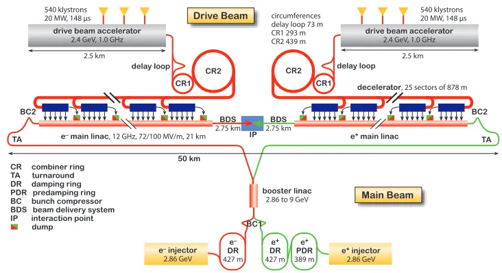
The CLIC accelerator [3] uses normal-conducting radio-frequency (RF) cavities to accelerate the main beams of electrons and positrons. In order to meet the energy and luminosity target within a few tens of kilometres many accelerating cavities (∼150,000) are needed, each with a high acceleration field of
∼100 MV m−1. Since standard RF sources scale unfavourably to high frequency, the CLIC approach is to make use of a low-frequency high-current drive beam to generate high-frequency RF (12 GHz). The drive beam itself is accelerated using conventional klystrons, and its frequency is increased using a series of delay loops and combiner rings as indicated in figure 2. The drive beam is then decelerated through a series of Power Extraction and Transfer Structures (PETS) creating high RF power that can be used to accelerate the main beams to 1.5 TeV. This two-beam concept, where the drive beam is used to deliver RF power to all the cavities along the main beam, has been demonstrated at CERN in the dedicated CLIC Test Facility (CTF).
The large number of accelerating cavities and decelerating structures constitute a big challenge, not only in precision during production but also in terms of operation where the breakdown rate needs
EPJ Web of Conferences 164, 01020 (2017) DOI: 10.1051/epjconf/201716401020
EPJ Web of Conferences
2013 - 2019 Development Phase Development of a Project Plan for a staged CLIC implementation in line with LHC results; technical developments with industry, performance studies for accelerator parts and systems, detector technology demonstrators
2020 - 2025 Preparation Phase Finalisation of implementation parameters, preparation for industrial procurement, Drive Beam Facility and other system verifications, Technical Proposal of the experiment, site authorisation
2025 Construction Start Ready for construction; start of excavations
2035 First Beams Getting ready for data taking by the time the LHC programme reaches completion 2019 - 2020 Decisions
Update of the European Strategy for Particle Physics; decision towards a next CERN project at the energy frontier (e.g. CLIC, FCC)
2026 - 2034 Construction Phase Construction of the first CLIC accelerator stage compatible with implementation of further stages; construction of the experiment; hardware commissioning
Figure 1. CLIC project timeline including important decisions and various planned phases for development, preparation, and construction. First beams are planned for 2035 and will be followed by 20 years of operation resulting in a rich physics program of both precision measurements as well as discovery. Credit: CLIC and CLICdp Collaboration.
In section 2 we will give a brief introduction to the accelerator complex and the challenging beam conditions at CLIC. In section 3 we will go through the detector requirements for a future CLIC experiment followed by an update of the latest CLIC detector model in section 4. The following sections go through the physics potential using illustrative example studies to map out the detector key capabilities. We conclude in section 8 with a short summary of these proceedings.
2 The CLIC accelerator
The CLIC accelerator [3] uses normal-conducting radio-frequency (RF) cavities to accelerate the main beams of electrons and positrons. In order to meet the energy and luminosity target within a few tens of kilometres many accelerating cavities (∼150,000) are needed, each with a high acceleration field of
∼100 MV m−1. Since standard RF sources scale unfavourably to high frequency, the CLIC approach is to make use of a low-frequency high-current drive beam to generate high-frequency RF (12 GHz). The drive beam itself is accelerated using conventional klystrons, and its frequency is increased using a series of delay loops and combiner rings as indicated in figure 2. The drive beam is then decelerated through a series of Power Extraction and Transfer Structures (PETS) creating high RF power that can be used to accelerate the main beams to 1.5 TeV. This two-beam concept, where the drive beam is used to deliver RF power to all the cavities along the main beam, has been demonstrated at CERN in the dedicated CLIC Test Facility (CTF).
The large number of accelerating cavities and decelerating structures constitute a big challenge, not only in precision during production but also in terms of operation where the breakdown rate needs
ICNFP 2016
(c)FT
TA BC2 delay loop
2.5 km
decelerator, 25 sectors of 878 m 540 klystrons 20 MW, 148 µs
CR2 CR1
circumferences delay loop 73 m CR1 293 m CR2 439 m
BDS
2.75 km
IP TA
BC2
delay loop
2.5 km 540 klystrons 20 MW, 148 µs
drive beam accelerator
2.4 GeV, 1.0 GHz
CR2 CR1
BDS
2.75 km
50 km CR combiner ring
TA turnaround DR damping ring PDR predamping ring BC bunch compressor BDS beam delivery system IP interaction point dump
drive beam accelerator
2.4 GeV, 1.0 GHz
Drive Beam
Main Beam
booster linac
2.86 to 9 GeV
e+ main linac e– main linac, 12 GHz, 72/100 MV/m, 21 km
e+ injector
2.86 GeV
e+ PDR
389 m
e+ DR
427 m
e– injector
2.86 GeV
e– DR
427 m
BC1
Figure 2. The CLIC accelerator at 3 TeV, including the drive beam complex at the top and the main beam at the bottom. The drive beam frequency is increased through a series of delay loops and combiner rings before reaching the desired bunch structure used to generate the high frequency RF power needed for the main beam acceleration. Credit: CLIC Collaboration.
to be kept at a manageable level. Further challenges for the CLIC accelerator complex come from the luminosity requirement, where a very small and dense beam, 40 nm x 1 nm in the transverse plane and
∼109particles per bunch, is needed to reach high enough statistics for rare processes at high energy. This puts constraints on both beam stability and alignment.
The beam and bunch structure of CLIC is rather distinct, with a bunch train repetition rate of 50 Hz. Each train consists of 312 bunches with a bunch spacing of 0.5 ns. Individual bunch crossings cannot be identified online, but the slow train repetition rate allows a readout of the complete detector during the 20 ms between bunch trains, making an offline selection possible (it is estimated that only
about one hard e+e−physics interaction will be produced per bunch train crossing) [1].
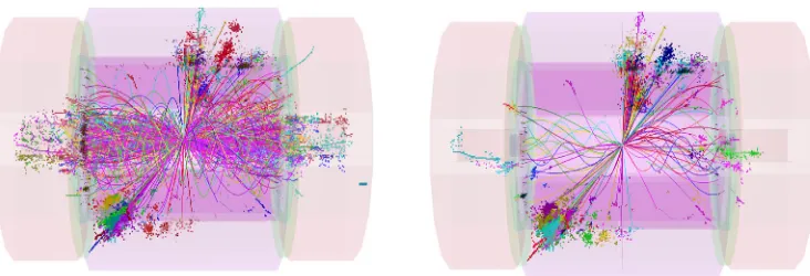
The very small beam size and high bunch charge leads to large electromagnetic fields and interac-tions between colliding bunches. The resulting background of e+e−pairs andγγ→hadrons, so-called
beamstrahlung, constitute a large experimental background for CLIC, predominately in the forward regions. It is estimated that around 3γγ → hadrons interaction occurs for every bunch crossing at
3 TeV, depositing ∼20 TeV per bunch train in the calorimeters. The background can be reduced to
a manageable level by applying combinedpT and timing cuts for the different subdetectors. Figure
3 shows an e+e− →H+H−→ t ¯bb¯t event before (left) and after (right) such cuts have been applied.
The cuts are designed to protect high pT physics objects. Using hadron-collider-like jet clustering algorithms with beam-jets further reduces the impact of the background on physics measurements.
The chiral nature of the weak force offers enhancement or suppression of different physical
pro-cesses by introducing polarisation of the main beams. For example WW-fusion Higgs production is greatly enhanced but the effect is less significant in other channels. In the baseline CLIC design a
polarisation of 80% in the electron beam is foreseen. Positron polarisation is considered an option for future upgrades of the CLIC facility.
EPJ Web of Conferences 164, 01020 (2017) DOI: 10.1051/epjconf/201716401020
EPJ Web of Conferences
2.5 TIMINGREQUIREMENTS ATCLIC
Table 2.4: Assumed time windows used for the event reconstruction and the required single hit time resolutions.
Subdetector Reconstruction window hit resolution
ECAL 10 ns 1 ns
HCAL Endcaps 10 ns 1 ns
HCAL Barrel 100 ns 1 ns
Silicon Detectors 10 ns 10/p12 ns
TPC entire bunch train n/a
is performed. Monte Carlo information is used at no stage in the reconstruction. Figure2.12shows the
reconstructed particle flow objects for a simulated e+e−!H+H−!tbbt event atps=3 TeV. At the
reconstruction level, the background fromgg!hadrons produces an average energy of approximately
1.2 TeV per event, mostly in the form of relatively lowpTparticles at relatively low angles to the beam axis. The level ofgg!hadrons background is roughly 1/15 of that for the entire bunch train (Table2.3),
commensurate with integrating over 10 ns from the total 156 ns. The background can be further reduced by applying tighter timing cuts based on the reconstructed calorimeter cluster time. The cluster time is obtained from a truncated mean of the energy-weighted hit times constituting the cluster. In a fine
grained particle flow detector many hits contribute to a single cluster andclustertime resolutions of
<1 ns are easily achievable. Efficient background rejection is achieved by using tight cuts in the range
of 1.0–2.5 ns on the clusters (depending on the type of reconstructed particle and itspT). This
proce-dure is applied to both neutral particle flow objects and to charged objects where the time of the cluster associated to the track, corrected by the helical propagation time, is used. These additional timing cuts are applied to only relatively lowpTparticle flow objects. The details of the cuts used are discussed in
Section12.1.4. As a result of the cluster-based timing cuts the average background level can be reduced
to approximately 100 GeV with negligible impact on the underlying hard interaction. The use of
hadron-collider inspired jet-finding algorithms further reduces the impact of the background ofgg!hadrons
and precision physics measurements are achievable in the CLIC background environment as shown in Chapter12.
Fig. 2.12: (left) Reconstructed particles in a simulated e+e−!H+H−!tbbt event at 3 TeV in the
CLIC_ILD detector concept with background fromgg!hadrons overlaid. (right) the effect of applying
tight timing cuts on the reconstructed cluster times.
61
Figure 3. The beam and bunch structure at CLIC induces a challenging experimental background of beam-strahlung events. The background is reduced by combined cuts in the different subdetectors protecting the im-portant highpTphysics objects. The left (right) hand side show an multi-jet e+e−→H+H−→t ¯bb¯t event at 3 TeV overlaid withγγ→hadrons background before (after) such cuts have been applied. Figures taken from [1].
3 Detector requirements
The performance requirements for the CLIC detector are driven by the physics goals, requiring:
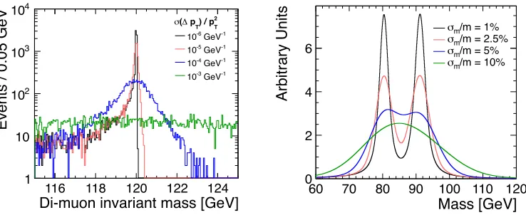
• Precise impact parameter resolution:σ2d0=(5µm)2+(15µm GeV)2/p2sin3θ, needed for accurate vertex reconstruction to enable flavour-tagging with clean b-, c- and light-quark jet separation,
• Excellent track-momentum resolution:σpT/p2T 2·10−5GeV−1, needed for Higgs recoil analysis
(see section 5), extraction of the position of kinematic edges (see section 7.1), etc. The impact
of different resolutions is illustrated in the left of figure 4 [4], showing the reconstructed di-muon
invariant mass for H→µ+
µ−events.
• Jet-energy resolution for high-energy jets: at least 3.5% above 100 GeV, needed to distinguish e.g.
W/Z/H di-jet decays. The effect of using various jet-mass resolutions is shown in the right of figure
4 [1] (a mass resolution of 2.5% corresponds to a jet-energy resolution of 3.5%),
• Overall need for precise timing to suppress background: translates to about 10 ns hit time-stamping
resolution in the tracking region and about 1 ns accuracy for calorimeter hits (the resolution for a cluster of hits<0.5 ns),
• Overall detector coverage (hermeticity), particularly in the forward region. This is needed for lepton
identification and missing energy.
4 CLIC detector overview
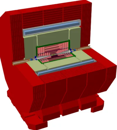
The CLIC detector design is based on the requirements outlined in section 3 and is optimised for a wide range of physics benchmark analyses. The current detector model is illustrated in figure 5 with the main features described below.
The innermost part of the CLIC detector consists of a low-mass vertex detector, containing 3 cylindrical double layers in the barrel and 3 spiral double layers in the forward regions. Each layer
corresponds to 0.2%X0(equivalent to about 200µm of Si). Such a small radiation length is needed
to reach the impact parameter resolution described in section 3. The detector design has roughly 2
EPJ Web of Conferences 164, 01020 (2017) DOI: 10.1051/epjconf/201716401020
EPJ Web of Conferences
2.5 TIMINGREQUIREMENTS ATCLIC
Table 2.4: Assumed time windows used for the event reconstruction and the required single hit time resolutions.
Subdetector Reconstruction window hit resolution
ECAL 10 ns 1 ns
HCAL Endcaps 10 ns 1 ns
HCAL Barrel 100 ns 1 ns
Silicon Detectors 10 ns 10/p12 ns
TPC entire bunch train n/a
is performed. Monte Carlo information is used at no stage in the reconstruction. Figure2.12shows the
reconstructed particle flow objects for a simulated e+e−!H+H−!tbbt event atps=3 TeV. At the
reconstruction level, the background fromgg!hadrons produces an average energy of approximately
1.2 TeV per event, mostly in the form of relatively lowpTparticles at relatively low angles to the beam axis. The level ofgg!hadrons background is roughly 1/15 of that for the entire bunch train (Table2.3),
commensurate with integrating over 10 ns from the total 156 ns. The background can be further reduced by applying tighter timing cuts based on the reconstructed calorimeter cluster time. The cluster time is obtained from a truncated mean of the energy-weighted hit times constituting the cluster. In a fine
grained particle flow detector many hits contribute to a single cluster andclustertime resolutions of
<1 ns are easily achievable. Efficient background rejection is achieved by using tight cuts in the range
of 1.0–2.5 ns on the clusters (depending on the type of reconstructed particle and its pT). This
proce-dure is applied to both neutral particle flow objects and to charged objects where the time of the cluster associated to the track, corrected by the helical propagation time, is used. These additional timing cuts are applied to only relatively lowpTparticle flow objects. The details of the cuts used are discussed in
Section12.1.4. As a result of the cluster-based timing cuts the average background level can be reduced
to approximately 100 GeV with negligible impact on the underlying hard interaction. The use of
hadron-collider inspired jet-finding algorithms further reduces the impact of the background ofgg!hadrons
and precision physics measurements are achievable in the CLIC background environment as shown in Chapter12.
Fig. 2.12: (left) Reconstructed particles in a simulated e+e−!H+H−!tbbt event at 3 TeV in the
CLIC_ILD detector concept with background fromgg!hadrons overlaid. (right) the effect of applying
tight timing cuts on the reconstructed cluster times.
61
Figure 3. The beam and bunch structure at CLIC induces a challenging experimental background of beam-strahlung events. The background is reduced by combined cuts in the different subdetectors protecting the im-portant highpTphysics objects. The left (right) hand side show an multi-jet e+e−→H+H−→t ¯bb¯t event at 3 TeV overlaid withγγ→hadrons background before (after) such cuts have been applied. Figures taken from [1].
3 Detector requirements
The performance requirements for the CLIC detector are driven by the physics goals, requiring:
• Precise impact parameter resolution:σ2d0=(5µm)2+(15µm GeV)2/p2sin3θ, needed for accurate vertex reconstruction to enable flavour-tagging with clean b-, c- and light-quark jet separation,
• Excellent track-momentum resolution:σpT/p2T2·10−5GeV−1, needed for Higgs recoil analysis
(see section 5), extraction of the position of kinematic edges (see section 7.1), etc. The impact
of different resolutions is illustrated in the left of figure 4 [4], showing the reconstructed di-muon
invariant mass for H →µ+
µ−events.
• Jet-energy resolution for high-energy jets: at least 3.5% above 100 GeV, needed to distinguish e.g.
W/Z/H di-jet decays. The effect of using various jet-mass resolutions is shown in the right of figure
4 [1] (a mass resolution of 2.5% corresponds to a jet-energy resolution of 3.5%),
• Overall need for precise timing to suppress background: translates to about 10 ns hit time-stamping
resolution in the tracking region and about 1 ns accuracy for calorimeter hits (the resolution for a cluster of hits<0.5 ns),
• Overall detector coverage (hermeticity), particularly in the forward region. This is needed for lepton
identification and missing energy.
4 CLIC detector overview
The CLIC detector design is based on the requirements outlined in section 3 and is optimised for a wide range of physics benchmark analyses. The current detector model is illustrated in figure 5 with the main features described below.
The innermost part of the CLIC detector consists of a low-mass vertex detector, containing 3 cylindrical double layers in the barrel and 3 spiral double layers in the forward regions. Each layer
corresponds to 0.2%X0(equivalent to about 200µm of Si). Such a small radiation length is needed
to reach the impact parameter resolution described in section 3. The detector design has roughly 2
ICNFP 2016
billion pixels, each 25µm square with a single point resolution of∼3µm. The vertex detector covers
the areaθ > 7◦ and is designed to consume very little power since there is no material budget for
liquid cooling. Cooling is achieved via an active air cooling strategy that induces a spiral airflow, and the power consumption is kept low via power-pulsing of the front-end electronics.
Moving outwards, the tracking system is complemented by a large silicon tracker with a radius of 1.5 m (4.6 m long) operating in a 4 T solenoid field. The inner (outer) tracker has 3 (3) barrel layers
and 7 (4) forward disks. The material budget allowed is only 1-2%X0 per layer. The sensors will
contain either large pixels or short strips with a granularity of approximately 50µm x (1 - 10) mm,
and a single point resolution of∼7µm. A minimum number of hits is required for pattern recognition,
which is why the tracking system is designed for at least 8 hits atθ >8◦per event.
The Electromagnetic calorimeter consists of 40 layers of tungsten absorbers interleaved with
sil-icon sensors of 300 micron thickness and with 5x5 mm2pads. The full depth of the electromagnetic
calorimeter corresponds to 23X0. The hadronic calorimeter consists of 60 layers of steel absorbers
interleaved with scintillator tiles of 30x30 mm2. The total depth of the hadronic calorimeter is 7.5λ
int. The whole calorimeter system is optimised for particle flow analysis (PFA) [5, 6].
The above mentioned detector components are all enclosed in a 4 T superconducting solenoid magnet with an inner radius of 3.4 m and a length of 8.3 m. The iron return yoke enclosing the magnet is instrumented with muon chambers than are used for muon identification. The detector also has a complex forward region with two important sub-detector systems: LumiCal (luminosity monitoring through Bhabha scattering) and BeamCal (beam monitoring and extended coverage for electromagnetic particles in the very forward region).
The physics studies presented in this proceeding were done using predecessors to the CLIC de-tector model presented above. These predecessors, CLIC_ILD and CLIC_SiD [1], are variants of the ILD and SiD [7] designs used at the International Linear Collider (ILC) but adapted for the CLIC
envi-ronment. These two models differ from each other primarily in the tracking system where the former
is using a time projection chamber (TPC), whereas the latter utilises a silicon tracker. All studies were
performed using a detector simulation of the physics events of interest overlaid withγγ→ hadrons
background.
10.5 Impact of the Momentum Resolution
]
°
[
θ
0 20 40 60 80
[GeV]
Tp
10 2 10 310 -1]
[GeV T
2
) / p T
p ∆ ( σ -5 10 -4 10 -3 10 ] -1 [GeV T 2 / p T p ∆
-0.3 -0.2 -0.1 0 0.1 0.2 0.3 -3 10 × Reconstructed muons 0 200 400 600 800
1000 h →µ+µ
-° < 30 µ θ ° > 30 µ θ All muons
Figure 10.14:∆pT/p2Tresolution of muons depending on the polar angle✓and the transverse momentum extracted from all fully simulated samples (left) and∆pT/p2Tresolution in h!µ+µ−events for di↵erent regions in✓(right).
Di-muon invariant mass [GeV]116 118 120 122 124
Events / 0.05 GeV
1 10 2 10 3 10 4 10 T 2 ) / p T p ∆ ( σ -1 GeV -6 10 -1 GeV -5 10 -1 GeV -4 10 -1 GeV -3 10 ] -1 [GeV T 2
) / p
T p ∆ ( σ -6
10 10-5 10-4
[%] BR × σ BR) × σ ( δ 0 10 20 30 40 -1
Fast sim, 2 ab
-1
Full sim, 2 ab
-1
Fast sim, 5 ab
-1
Full sim, 5 ab
Figure 10.15: Di-muon invariant mass distribution for di↵erent∆pT/p2Tresolutions (left) and relative statistical uncertainty on the h!µ+µ−cross section times branching ratio measurement depending on the∆pT/p2
T resolu-tion for an integrated luminosity of 2 and 5 ab−1(right).
previous sections using the same boosted decision tree. Only the BDT selection cut has been changed to optimize the significance. The di-muon invariant mass distribution of the signal and background contributions are fitted to obtain their expected shapes and the cross section times branching ratio is
extracted from 100 toy Monte Carlo experiments. The impact of theγγ !hadrons background is not
included but expected to be similar to the results obtained in Section10.4.
Fig.10.15(right) shows the resulting statistical uncertainty on the cross section times branching ratio
measurement depending on the momentum resolution, assuming a total integrated luminosity of 2 ab−1
and 5 ab−1, respectively. The points corresponding to the result from the full simulation sample obtained in Section10.3.3are consistent with the results obtained from fast simulations. The relative statistical
uncertainty degrades noticeably for momentum resolutions worse than a few times 10−5GeV−1. The
measurement does not improve for better momentum resolutions because of the intrinsic statistical
fluc-121
2 CLIC EXPERIMENTALCONDITIONS ANDDETECTORREQUIREMENTS
Mass [GeV]
60 70 80 90 100 110 120
Arbitrary Units
0 2 4 6
/m = 1% m
σ
/m = 2.5% m
σ /m = 5% m
σ
/m = 10% m
σ
[GeV] C M
400 600 800 1000 1200
C dN/dM 0 0.005 0.01 0.015 no smearing /E = 3% E
σ
/E = 5% E
σ
/E = 10% E
σ
Fig. 2.6: (left) Ideal W/Z separation vs. jet mass resolution obtained using a Gaussian smearing of Breit-Wigner distributions; (right) Reconstructed contravariant mass,MC, for e+e−!eqReqR!qec0qec0
(including the effects of Beamstrahlung) for different jet energy resolutions. The plot was obtained by applying a Gaussian energy smearing to reconstructed jets based on the generator level particles.
2.2.4 Forward Coverage
At CLIC manySMprocesses will result in particles produced at relatively low angles to the beam axis; either due to the boost along the beam axis from beamstrahlung or fromt-channel processes. To study these processes, on the one hand, or to reduce their impact onBSMphysics studies, on the other hand, extending the detector coverage to small polar angles is important [22].
For example, at 3 TeV, approximately 80% of the leptons in the l+l−l+l−final state, dominated by gauge boson pairs, are produced at polar angles of<30◦to the beam axis. The forward region is also important for physics signatures with missing energy. It helps to reject background processes like multi-peripheral two photon processes, e+e−!e+e−ff¯, where the scattered electrons are usually at low polar angles. For example, forward electron tagging is essential to reject the e+e−!e+e−µ+µ−background in the measurement of the Higgs branching ratio into two muons. As shown in Section12.4.2, it im-proves the achievable statistical accuracy of this measurement from 23% to 15%, assuming an integrated luminosity of 2 ab−1and 95% electron tagging efficiency down to ⇡40 mrad polar angle. Another
example is the production and decay of stau pairs, e+e−!etet!t+t−ec0
1ec01, which, in some regions of SUSYparameter space, results in a signal with relatively small missing transverse momentum. In this case, the e+e−!e+e−t+t−and e+e−!e+e−qq background processes need to be rejected by efficient electron tagging at low polar angles. It is therefore important, in general, to provide precision tracking and calorimetry coverage down to small angles, and to extend the forward electron tagging capabilities to very low angles.
2.2.5 Lepton ID Requirements
Many of the potentialBSMphysics signals at CLIC will rely on the ability to efficiently identify high energy electrons and muons, and efficient lepton identification is central to the CLIC detector require-ments. For efficient selection of final states with two or more leptons, lepton identification efficiencies of more than 95% over a wide range of momenta are highly desirable. In addition the identification of leptons in jets from semi-leptonic decays of b- and c-quarks will benefit heavy flavour tagging.
Figure 4.Left: Di-muon invariant mass distribution in a search for H→µ+µ−decays at √s=3 TeV for different
σp T/p
2
Tresolutions. Figure taken from [4]. Right: The required W/Z jet mass separation is obtained for mass resolutions below 2.5%, corresponding to a jet-energy resolution of 3.5%. Figure taken from [1].
5
EPJ Web of Conferences 164, 01020 (2017) DOI: 10.1051/epjconf/201716401020
EPJ Web of Conferences
Figure 5.The CLIC detector model. Starting from the innermost part it consists of a low mass vertex detector, a large radius tracker detector, and a calorimeter system optimised for particle flow analysis. These parts are enclosed in a 4 T solenoid field. The outermost layer consists of the return yolk of the magnetic field and is instrumented with muon detectors. Credit: CLICdp Collaboration.
5 Higgs physics at CLIC
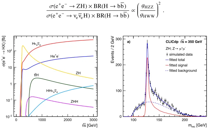
The clean collision environment of an electron-positron collider is ideal for precision physics studies of the Higgs boson, a prime target of CLIC operation at 380 GeV. CLIC is a Higgs factory covering several Higgs production processes as can be seen on the left hand side of figure 6 where the cross-sections of various Higgs processes are shown as a function of centre-of-mass energy of the collisions. At the initial energy stage roughly 70,000 Higgsstrahlung events are produced, and about 3 million Higgs bosons will be produced at the two higher energy stages.
5.1 Higgsstrahlung
The Higgsstrahlung production mode (e+e− → HZ), illustrated in the leftmost diagram of figure 7,
allows for a model-independent measurement of the absolute coupling of the Higgs boson to the Z boson, which is unique for lepton colliders [8]. This is achieved by studying the mass recoiling against the Z boson for events with two oppositely charged leptons that have an invariant mass consistent with
mZ. The right side of figure 6 shows the Z-recoil mass for Z → µ+µ−events at a studied benchmark
energy of 350 GeV where the cross-section is dominant and close to maximal. The remainder of the event, i.e. the particles from the Higgs decay, is not considered in the event selection, giving a result that is independent of specific Higgs decay modes. Note that this also applies to potential invisible final states. This technique for determining the absolute HZZ coupling is possible due to the well-defined initial state and clean experimental conditions at a linear collider.
EPJ Web of Conferences 164, 01020 (2017) DOI: 10.1051/epjconf/201716401020
EPJ Web of Conferences
Figure 5.The CLIC detector model. Starting from the innermost part it consists of a low mass vertex detector, a large radius tracker detector, and a calorimeter system optimised for particle flow analysis. These parts are enclosed in a 4 T solenoid field. The outermost layer consists of the return yolk of the magnetic field and is instrumented with muon detectors. Credit: CLICdp Collaboration.
5 Higgs physics at CLIC
The clean collision environment of an electron-positron collider is ideal for precision physics studies of the Higgs boson, a prime target of CLIC operation at 380 GeV. CLIC is a Higgs factory covering several Higgs production processes as can be seen on the left hand side of figure 6 where the cross-sections of various Higgs processes are shown as a function of centre-of-mass energy of the collisions. At the initial energy stage roughly 70,000 Higgsstrahlung events are produced, and about 3 million Higgs bosons will be produced at the two higher energy stages.
5.1 Higgsstrahlung
The Higgsstrahlung production mode (e+e− → HZ), illustrated in the leftmost diagram of figure 7,
allows for a model-independent measurement of the absolute coupling of the Higgs boson to the Z boson, which is unique for lepton colliders [8]. This is achieved by studying the mass recoiling against the Z boson for events with two oppositely charged leptons that have an invariant mass consistent with
mZ. The right side of figure 6 shows the Z-recoil mass for Z →µ+µ−events at a studied benchmark
energy of 350 GeV where the cross-section is dominant and close to maximal. The remainder of the event, i.e. the particles from the Higgs decay, is not considered in the event selection, giving a result that is independent of specific Higgs decay modes. Note that this also applies to potential invisible final states. This technique for determining the absolute HZZ coupling is possible due to the well-defined initial state and clean experimental conditions at a linear collider.
ICNFP 2016
The uncertainty on the HZZ coupling is calculated to 2% using the leptonic Z decays. These decays give the cleanest signature, but the result can be improved significantly by adding the large statistics from the hadronic Z decays. The combined uncertainty on the HZZ coupling is about 0.8%. The analysis described above can also be used to put constraints on the Higgs branching ratio to invisible states: the estimated uncertainty is below 1% at 90% confidence level [9].
5.2 Higgs production at higher energies
At higher energies the Higgs production is dominated by vector boson fusion where either W or Z bosons fuse to produce a Higgs boson, see the middle and right diagram of figure 7. The dominant WW-fusion process gives a constraint on the H coupling to W and also gives the best sensitivity for the Higgs mass and Higgs total decay width. The Higgs mass can be extracted with a precision of 24 MeV (including electron polarisation) using a combination of both high energy stages (1.5 and 3 TeV). This precision compares favourably with the HL-LHC projection of 50 MeV per experiment [10].
Rarer Higgs decays, with branching ratios at the sub-% level, such as H → µ+µ−, H → γγ, and
H→Zγ, also benefit from the higher statistics at high energies. Here we reach an uncertainty on the
cross-section×branching ratio for the three processes mention above of 25% (with CLIC at 3 TeV),
15% (with CLIC at 1.4 TeV), and 42% (with CLIC at 1.4 TeV) respectively [9].
Once the Higgs coupling to the Z,gHZZ, has been determined using the recoil mass technique,
the Higgs coupling to W,gHWW, can be determined by studying the cross-section×branching ratio
fraction between Higgsstrahlung and WW-fusion events, e.g. using b-tagged events,
σ(e+e−→ZH)×BR(H→bb)
σ(e+e−→νeνeH)×BR(H→bb) ∝ gHZZ
gHWW
2 . (1)
[GeV] s
0 1000 2000 3000
HX) [fb]
→
-e
+
(e
σ
2
− 10
1
− 10
1 10 2 10
e
ν
e
ν
H
-e + He
ZH
ZHH H
tt
e
ν
e
ν
HH
[GeV]
rec
m
100 150 200
Events / 2 GeV
0 100 200 300
simulated data fitted total fitted signal fitted background
-µ + µ →
ZH; Z
= 350 GeV s CLICdp a)
Figure 6. Left: Dominant Higgs production cross-sections at CLIC as a function of center-of-mass collision energy. The distributions shown correspond to unpolarised beams and do not include the effects of initial-state radiation (ISR) or beamstrahlung. The plot is produced using perturbative NLO calculation with the generator Whizard 1.95. Figure taken from [9]. Right: The Z-recoil mass for Z→µ+µ−events at a studied benchmark energy of 350 GeV. Figure taken from [9].
EPJ Web of Conferences 164, 01020 (2017) DOI: 10.1051/epjconf/201716401020
EPJ Web of Conferences
Z
e− e+
H Z
W W
e− e+
νe
H
νe
Z Z
e− e+
e− H e+
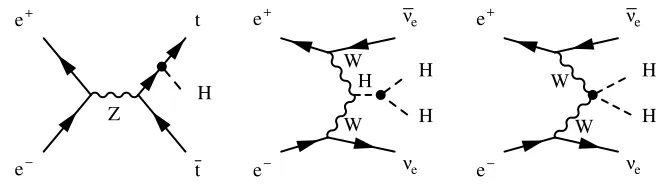
Figure 7.The three highest cross-section Higgs production processes at CLIC.
Z
e− e+
t H t
W W H
e− e+
νe
H H
νe
W W
e− e+
νe
H H
νe
Figure 8. Higgs processes at CLIC involving the top Yukawa couplinggHtt, the Higgs boson trilinear self-couplingλand the quartic couplinggHHWW.
In order to determine absolute measurements of other Higgs couplings, the Higgs total decay
width needs to be derived from the data1. For example it can be determined by measuring the Higgs
decay to WW∗in the WW-fusion process,
σ(Hνeνe)×BR(H→WW∗)∝g
4 HWW
ΓH , (2)
given that the model-independent measurement ofgHWWwas derived following equation 1 above. In
practice however, both the Higgs couplings and the total decay width are determined through a global fit of all available experimental measurements involving the Higgs boson processes, see section 5.2.1. Another interesting process accessible at the second and third stages of CLIC is the top Yukawa process illustrated in the left diagram of figure 8. In this process a Higgs boson is produced in
asso-ciation with a pair of top quarks. The channel with the dominant decay mode, H → b ¯b, has eight
fermions in the final sample, including four b-jets. Naturally flavour tagging information is one of the crucial elements to distinguish the signal from the background. Therefore this process also provides an excellent detector benchmark test. The precision reached with CLIC using both the fully-hadronic and semi-leptonic final states is 4-5% [9] at 1.4 TeV. As a comparison, for HL-LHC the prediction is 7-10% [10] per experiment.
Double Higgs production e+e− → HHν
eνe, as illustrated in the middle and right diagrams of
figure 8, is best reachable at the highest energy scale of 3 TeV. The high energy is crucial in order to
1The total Higgs decay width,Γ
H, is less than 5 MeV and hence too small to be measured directly with current experiments. EPJ Web of Conferences 164, 01020 (2017) DOI: 10.1051/epjconf/201716401020
EPJ Web of Conferences
Z
e− e+
H Z
W W
e− e+
νe
H
νe
Z Z
e− e+
e− H e+
Figure 7.The three highest cross-section Higgs production processes at CLIC.
Z
e− e+
t H t
W W H
e− e+
νe
H H
νe
W W
e− e+
νe
H H
νe
Figure 8. Higgs processes at CLIC involving the top Yukawa couplinggHtt, the Higgs boson trilinear self-couplingλand the quartic couplinggHHWW.
In order to determine absolute measurements of other Higgs couplings, the Higgs total decay
width needs to be derived from the data1. For example it can be determined by measuring the Higgs
decay to WW∗in the WW-fusion process,
σ(Hνeνe)×BR(H→WW∗)∝g
4 HWW
ΓH , (2)
given that the model-independent measurement ofgHWWwas derived following equation 1 above. In
practice however, both the Higgs couplings and the total decay width are determined through a global fit of all available experimental measurements involving the Higgs boson processes, see section 5.2.1. Another interesting process accessible at the second and third stages of CLIC is the top Yukawa process illustrated in the left diagram of figure 8. In this process a Higgs boson is produced in
asso-ciation with a pair of top quarks. The channel with the dominant decay mode, H → b ¯b, has eight
fermions in the final sample, including four b-jets. Naturally flavour tagging information is one of the crucial elements to distinguish the signal from the background. Therefore this process also provides an excellent detector benchmark test. The precision reached with CLIC using both the fully-hadronic and semi-leptonic final states is 4-5% [9] at 1.4 TeV. As a comparison, for HL-LHC the prediction is 7-10% [10] per experiment.
Double Higgs production e+e− → HHν
eνe, as illustrated in the middle and right diagrams of
figure 8, is best reachable at the highest energy scale of 3 TeV. The high energy is crucial in order to
1The total Higgs decay width,Γ
H, is less than 5 MeV and hence too small to be measured directly with current experiments.
ICNFP 2016
coupling relative to SM
0.8 1 1.2
1% 5%
H
Γ µ
c τ b t W Z g γ γ
Z H CLICdp
model independent 350 GeV+ 1.4 TeV + 3 TeV
coupling relative to SM
0.9 1 1.1
0.5% 2.5%
H
Γ µ
c τ b t
W Z g
γ
γ
Z H CLICdp
model dependent 350 GeV+ 1.4 TeV + 3 TeV
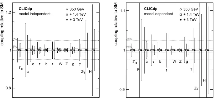
Figure 9. Illustration of the precision of the Higgs couplings and decay width of the studied three-stage CLIC programme. Figures taken from [9]. Left: Results using a independent fit. Right: Results using a model-dependent fit as described in 5.2.1.
profit from the higher cross-section and higher luminosity at this energy. This channel gives access to
the Higgs tri-linear self-couplingλ, a direct probe of the Higgs potential, at the precision of about 10%
for 1.4 TeV and 3 TeV operation combined [9]. This is considerably more precise than the predicted
precision of∼30% for the HL-LHC.
5.2.1 Global Higgs fit
The global fit results of the full CLIC program, i.e.∼5-7 years of running at each stage, is presented
in figure 9, where the model-independent (model-dependent) couplings are shown to the left (right).
In general, model-independent couplings can be determined down to∼2% for most couplings while
model-dependent couplings can be determined to∼0.1-1%2. The accuracy on the Higgs total decay
width is∼3.6% (model-independent) [9],∼0.3% (model-dependent, derived) [9]. It should be noted
that CLIC sensitivity is significantly better than HL-LHC for the couplings to c, b, W, Z, and g, the
self-coupling and the Higgs total decay width. Further the couplings toµ,τ, t,γ, and Zγare at a
similar level of sensitivity.
6 Top physics at CLIC
The top quark is of particular interest due to its strong coupling to the Higgs field; a precise measure-ment of the top quark mass is needed to verify the relation between the top quark and the SM gauge bosons. Further, precision top quark studies may be a prominent place where indications of potential new physics show up. The determination of the top quark mass and the top quark couplings to Z and
γwith high precision are among the main focuses of the initial stage of CLIC. Rare decays such as
t→cH and t→cγcan also be studied and here CLIC provides competitive limits.
2The fit is done in the same manner as for the LHC experiments, i.e. assuming no invisible Higgs decays, leading to a model-dependence.
EPJ Web of Conferences 164, 01020 (2017) DOI: 10.1051/epjconf/201716401020
EPJ Web of Conferences
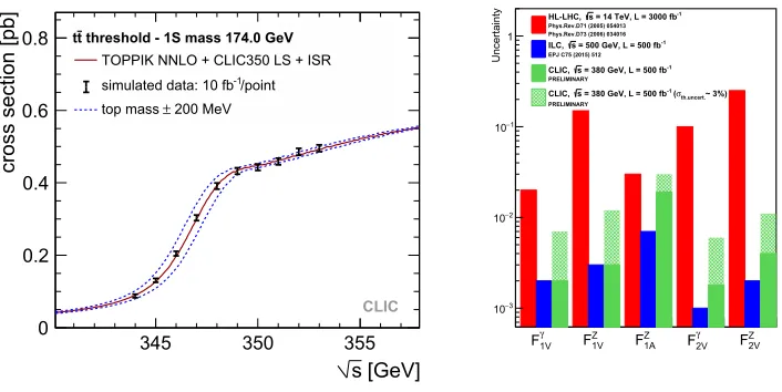
As mentioned in section 1 the CLIC staging program includes a dedicated threshold scan around 350 GeV to measure the top quark mass. This is shown in the left of figure 10, where the tt production
cross-section is shown as a function of centre-of-mass energy for 10 measurements of 10 fb−1 each
[11]. The position of the threshold is related to the top quark mass, and the slope of the rise in cross-section around the threshold reflects its natural width. From the normalisation we can extract a measurement of the strong coupling constant and the top Yukawa coupling. While the former is sensitive to QCD corrections close to the threshold where the tt-system experiences QCD bound state effects, the latter is related to H loop corrections.
Extraction of the theoretically well-defined 1S top quark mass can be done with a statistical accu-racy of about 30 MeV [11, 12]. At this level of precision we expect the experimental and theoretical systematic uncertainties to become relevant. The theoretical uncertainty includes the uncertainty in the NNNLO description of the threshold shape and the uncertainty in the conversion of the thresh-old mass to the minimal subtraction MS scheme [13]. A total uncertainty on the top quark mass of about 50 MeV [12] seems feasible, which is about one order of magnitude beyond the capabilities of HL-LHC.
The top gauge couplings can be determined through measurements of cross-sections and
forward-backward asymmetries for different polarisations [14]. The general t¯tV vertex can be parameterised
using either form factors or effective operators. The related parameters are substantially modified in
many BSM models, e.g. in models with extra dimensions and new heavy gauge bosons. The right side of figure 10 shows a comparison of the uncertainty on the measured top quark form factors. The precision reached by CLIC (at the level of 1% or below) is shown in green, and foresees an order of magnitude better precision than HL-LHC shown in red [2]. Further, the fact that the top quark decays before it hadronizes allows access to its polarisation by measuring the angular distributions of the decay products. This is a sensitive probe for CP violation in the top sector.
[GeV] s
345 350 355
cross section [pb]
0 0.2 0.4 0.6
0.8 tt threshold - 1S mass 174.0 GeV
TOPPIK NNLO + CLIC350 LS + ISR /point
-1
simulated data: 10 fb 200 MeV
±
top mass
CLIC
γ
1V
F Z
1V
F Z
1A
F γ
2V
F Z
2V
F
Uncertainty
3 −
10
2 −
10
1 −
10
1 Phys.Rev.D73 (2006) 034016 Phys.Rev.D71 (2005) 054013
-1 = 14 TeV, L = 3000 fb s
HL-LHC,
EPJ C75 (2015) 512 -1 = 500 GeV, L = 500 fb s
ILC,
PRELIMINARY
-1 = 380 GeV, L = 500 fb s
CLIC,
PRELIMINARY th.uncert.~ 3%) σ ( -1 = 380 GeV, L = 500 fb s
CLIC,
Figure 10.Left: Cross-section of tt production as function of centre-of-mass energy for 10 measurement points of 10 fb−1 each around the top quark threshold mass. For illustration a±200 MeV mass shift is indicated by dashed lines. Figure taken from [11]. Right: Comparisons of the uncertainty on the measured top quark form factors (considering parity conserving couplings). Figure taken from [2].
EPJ Web of Conferences 164, 01020 (2017) DOI: 10.1051/epjconf/201716401020
EPJ Web of Conferences
As mentioned in section 1 the CLIC staging program includes a dedicated threshold scan around 350 GeV to measure the top quark mass. This is shown in the left of figure 10, where the tt production
cross-section is shown as a function of centre-of-mass energy for 10 measurements of 10 fb−1 each
[11]. The position of the threshold is related to the top quark mass, and the slope of the rise in cross-section around the threshold reflects its natural width. From the normalisation we can extract a measurement of the strong coupling constant and the top Yukawa coupling. While the former is sensitive to QCD corrections close to the threshold where the tt-system experiences QCD bound state effects, the latter is related to H loop corrections.
Extraction of the theoretically well-defined 1S top quark mass can be done with a statistical accu-racy of about 30 MeV [11, 12]. At this level of precision we expect the experimental and theoretical systematic uncertainties to become relevant. The theoretical uncertainty includes the uncertainty in the NNNLO description of the threshold shape and the uncertainty in the conversion of the thresh-old mass to the minimal subtraction MS scheme [13]. A total uncertainty on the top quark mass of about 50 MeV [12] seems feasible, which is about one order of magnitude beyond the capabilities of HL-LHC.
The top gauge couplings can be determined through measurements of cross-sections and
forward-backward asymmetries for different polarisations [14]. The general t¯tV vertex can be parameterised
using either form factors or effective operators. The related parameters are substantially modified in
many BSM models, e.g. in models with extra dimensions and new heavy gauge bosons. The right side of figure 10 shows a comparison of the uncertainty on the measured top quark form factors. The precision reached by CLIC (at the level of 1% or below) is shown in green, and foresees an order of magnitude better precision than HL-LHC shown in red [2]. Further, the fact that the top quark decays before it hadronizes allows access to its polarisation by measuring the angular distributions of the decay products. This is a sensitive probe for CP violation in the top sector.
[GeV] s
345 350 355
cross section [pb]
0 0.2 0.4 0.6
0.8 tt threshold - 1S mass 174.0 GeV
TOPPIK NNLO + CLIC350 LS + ISR /point
-1
simulated data: 10 fb 200 MeV ± top mass CLIC γ 1V F Z 1V F Z 1A F γ 2V F Z 2V F Uncertainty 3 − 10 2 − 10 1 − 10
1 Phys.Rev.D73 (2006) 034016 Phys.Rev.D71 (2005) 054013
-1 = 14 TeV, L = 3000 fb s
HL-LHC,
EPJ C75 (2015) 512 -1 = 500 GeV, L = 500 fb s
ILC,
PRELIMINARY
-1 = 380 GeV, L = 500 fb s
CLIC,
PRELIMINARY th.uncert.~ 3%) σ ( -1 = 380 GeV, L = 500 fb s
CLIC,
Figure 10.Left: Cross-section of tt production as function of centre-of-mass energy for 10 measurement points of 10 fb−1 each around the top quark threshold mass. For illustration a±200 MeV mass shift is indicated by dashed lines. Figure taken from [11]. Right: Comparisons of the uncertainty on the measured top quark form factors (considering parity conserving couplings). Figure taken from [2].
ICNFP 2016
[GeV]
jj,1M
40 60 80 100 120 140 160
[GeV]
jj,2M
40 60 80 100 120 140 160 0 10 20 30 40 50 -W + W → -1 χ + 1 χ hh → 0 2 χ 0 2 χ hZ → 0 2 χ 0 2 χ)
2Di-Jet Invariant Mass (GeV/c
600 800 1000 1200 1400-1
Entries / 2 ab
0 20 40 60 80 100 120 HA -H + H WW ZZ tt+4b WWZ+ZZZ
Figure 11. Left: The reconstructed di-jet masses from the decay product of directly produced charginos and neutralinos. Figure taken from [1]. Right: The reconstructed di-jet mass in a scenario with heavy Higgs bosons. Figure taken from [1].
At high-energy CLIC operation, an increased boost leads to better separation between the decay products of the two top quarks. A top tagging algorithm based on the method presented in [15] is under development and currently being re-optimised for electron-positron collisions. The focus is on
further exploration of top gauge couplings. For example for effective D6 operators we see a significant
improvement going to higher energies. Further, initial studies of the CKM matrix elementνtb, through
the study of single top production e+γ
→t+b+ν¯look promising. This process has no background
from t¯t.
7 BSM physics at CLIC
In addition to the Higgs and top physics programs outlined in section 5 and 6, CLIC also has an excellent sensitivity to BSM physics through both direct and indirect measurements. Due to the clean collision environment CLIC is particularly suited to study non-colored TeV-scale particles such as for example sleptons and charginos in supersymmetry (SUSY). These might be hidden in the large QCD backgrounds at the LHC. To quantify the performance and give input to the detector optimisation
effort, three different SUSY scenarios were defined and used as benchmark signal samples for various
BSM analyses [1]. In general each analysis was able to measure the mass and other basic properties of the particles set out to find. A small selection of the BSM benchmark analyses are highlighted in section 7.1 and 7.2.
7.1 Direct searches for BSM physics
Direct production of new particles is possible up to the kinematic limit (√s/2 for particles produced
in pairs). This includes studying e.g. mono-photon events allowing model-independent searches for dark matter. Below we show a few examples of analyses concerning the reconstruction and direct measurements of possible SUSY particles.
EPJ Web of Conferences 164, 01020 (2017) DOI: 10.1051/epjconf/201716401020
EPJ Web of Conferences
Slepton signatures are particularly clean with two high-momentum leptons and missing energy in the final state (e+e− → µ+
Rµ−R → µ+µ−χ˜01χ˜01). The slepton and gauginos masses are extracted from the position of the kinematic edges of the lepton energy distribution, the so-called endpoints. The
precision on slepton masses is below 1 % for sleptons with a mass∼1 TeV.
Also hadronic events were studied, e.g. through the pair-production of charginos (e+e−→χ˜1
1χ˜11→ ˜
χ0
1χ˜01W+W−) and neutralinos (e.g. e+e− → χ˜02χ˜02 → HH ˜χ01χ˜01), reconstructed into 4 jets and missing
energy, see figure 11. The precision,∆m/m, on gaugino masses of a few hundred GeV is roughly
1-1.5%.
Scenarios with heavy Higgs bosons typically have complex final states, e.g. e+e− → H0A →
b ¯bb ¯b and e+e−→ H+H− →t ¯bb¯t, requiring precise flavour tagging. The H
0, A0, and H±states are almost degenerate in mass. The right side of figure 11 shows the di-jet invariant mass distribution for
the b ¯bb ¯b final states. Here CLIC reaches as mass precision∆m/m=0.3% [1].
7.2 Indirect searches for BSM physics
Indirect searches are conducted by studying the variables and couplings in the SM with very high precision and allow discovery of BSM signals beyond the centre-of-mass energy of the collider. For
example Zand Higgs compositeness models can be probed up to scales of tens of TeV [10, 16].
Zis a hypothetical gauge boson arising from extensions of the electroweak symmetry of the SM.
This can be described e.g. in so-called Minimal anomaly-free Zmodels (AFZ). These are accessible
by precision studies of e+e− → µ+µ− including measurements of the cross-section and both the
forward-backwards and left-right asymmetry. Model-dependence arise through mixing of the Zand
Z and allow for discovery up to 50 TeV [16]. In case a Zis indeed found in LHC or HL-LHC data,
CLIC can measure the effective couplings with high precision.
Another important analysis is the study of vector boson scattering (VBS). While the SM Higgs preserve the unitarity of scattering amplitudes in longitudinal VBS, anomalous couplings or additional resonances can be introduced in BSM models. At first glance, CLIC at 3 (1.5) TeV is roughly two (one) orders of magnitude more precise for anomalous couplings than LHC at 8 TeV.
8 Conclusions & Summary
CLIC has a well-established physics program that spans over several decades with a three-stage
im-plementation. CLIC opens up the possibility of e+e−collisions with √s 1 TeV, giving improved
precision of many observables, access to rare Higgs decays, and discovery potential for BSM physics at the energy frontier with a reach in indirect search up to tens of TeV.
A model-independent measurement of the HZZ coupling can be extracted at the initial stage at 380 GeV. This stage also includes a dedicated threshold scan to precisely measure the top mass. At the two higher energy stages, 1.5 TeV and 3 TeV, statistics improve for the rare Higgs decays and we get direct access to e.g. the top Yukawa coupling and the Higgs self-coupling.
The feasibility of the CLIC program has been demonstrated through extensive simulation, proto-typing, and accelerator and detector R&D. Results from the LHC provide an important input for the
CLIC physics program, a strategy that can be adapted to potential LHC/HL-LHC discoveries.
References
[1] L. Linssen et al.,CLIC Conceptual Design Report: Physics and Detectors at CLIC,
CERN-2012-003 (2012)
EPJ Web of Conferences 164, 01020 (2017) DOI: 10.1051/epjconf/201716401020
EPJ Web of Conferences
Slepton signatures are particularly clean with two high-momentum leptons and missing energy in the final state (e+e− → µ+
Rµ−R → µ+µ−χ˜01χ˜01). The slepton and gauginos masses are extracted from the position of the kinematic edges of the lepton energy distribution, the so-called endpoints. The
precision on slepton masses is below 1 % for sleptons with a mass∼1 TeV.
Also hadronic events were studied, e.g. through the pair-production of charginos (e+e−→χ˜1
1χ˜11→ ˜
χ0
1χ˜01W+W−) and neutralinos (e.g. e+e− → χ˜02χ˜02 → HH ˜χ01χ˜01), reconstructed into 4 jets and missing
energy, see figure 11. The precision,∆m/m, on gaugino masses of a few hundred GeV is roughly
1-1.5%.
Scenarios with heavy Higgs bosons typically have complex final states, e.g. e+e− → H0A →
b ¯bb ¯b and e+e−→ H+H− → t ¯bb¯t, requiring precise flavour tagging. The H
0, A0, and H±states are almost degenerate in mass. The right side of figure 11 shows the di-jet invariant mass distribution for
the b ¯bb ¯b final states. Here CLIC reaches as mass precision∆m/m=0.3% [1].
7.2 Indirect searches for BSM physics
Indirect searches are conducted by studying the variables and couplings in the SM with very high precision and allow discovery of BSM signals beyond the centre-of-mass energy of the collider. For
example Zand Higgs compositeness models can be probed up to scales of tens of TeV [10, 16].
Zis a hypothetical gauge boson arising from extensions of the electroweak symmetry of the SM.
This can be described e.g. in so-called Minimal anomaly-free Zmodels (AFZ). These are accessible
by precision studies of e+e− → µ+µ− including measurements of the cross-section and both the
forward-backwards and left-right asymmetry. Model-dependence arise through mixing of the Zand
Z and allow for discovery up to 50 TeV [16]. In case a Zis indeed found in LHC or HL-LHC data,
CLIC can measure the effective couplings with high precision.
Another important analysis is the study of vector boson scattering (VBS). While the SM Higgs preserve the unitarity of scattering amplitudes in longitudinal VBS, anomalous couplings or additional resonances can be introduced in BSM models. At first glance, CLIC at 3 (1.5) TeV is roughly two (one) orders of magnitude more precise for anomalous couplings than LHC at 8 TeV.
8 Conclusions & Summary
CLIC has a well-established physics program that spans over several decades with a three-stage
im-plementation. CLIC opens up the possibility of e+e−collisions with √s1 TeV, giving improved
precision of many observables, access to rare Higgs decays, and discovery potential for BSM physics at the energy frontier with a reach in indirect search up to tens of TeV.
A model-independent measurement of the HZZ coupling can be extracted at the initial stage at 380 GeV. This stage also includes a dedicated threshold scan to precisely measure the top mass. At the two higher energy stages, 1.5 TeV and 3 TeV, statistics improve for the rare Higgs decays and we get direct access to e.g. the top Yukawa coupling and the Higgs self-coupling.
The feasibility of the CLIC program has been demonstrated through extensive simulation, proto-typing, and accelerator and detector R&D. Results from the LHC provide an important input for the
CLIC physics program, a strategy that can be adapted to potential LHC/HL-LHC discoveries.
References
[1] L. Linssen et al., CLIC Conceptual Design Report: Physics and Detectors at CLIC,
CERN-2012-003 (2012)
ICNFP 2016
[2] M. J. Boland et al. [CLIC and CLICdp Collaborations],Updated baseline for a staged Compact
Linear Collider, CERN-2016-004 (2016)
[3] M. Aicheler et al., CLIC Conceptual Design Report: A Multi-TeV Linear Collider Based on
CLIC Technology, CERN-2012-007 (2012)
[4] C. Grefe,Detector Optimization Studies and Light Higgs Decay into Muons at CLIC, PhD
The-sis, CERN-THESIS-2012-344, BONN-IR-2013-14 (2012)
[5] M. A. Thomson, Particle Flow Calorimetry and the PandoraPFA Algorithm, Nucl. Instrum.
Meth.A611(2009)
[6] J. S. Marshall, A. Munnich and M. A. Thomson,Performance of Particle Flow Calorimetry at
CLIC, Nucl. Instrum. Methods Phys. Res. A700(2012)
[7] H. Abramowicz et al.,The International Linear Collider Technical Design Report - Volume 4:
Detectors, ILC-REPORT-2013-040 (2013)
[8] M. A. Thomson,Model-independent measurement of the e+e−→ HZ cross section at a future
e+
e−linear collider using hadronic Z decays, Eur. Phys. J. C76(2016)
[9] H. Abramowicz et al., Higgs Physics at the CLIC Electron-Positron Linear Collider,
arXiv:1608.07538 (2016)
[10] S. Dawson et al.,Higgs Working Group Report of the Snowmass 2013 Community Planning
Study, Proceedings of the Community Summer Study 2013: Snowmass on the Mississippi, CNUM: C13-07-29.2, arXiv:1310.8361 (2013)
[11] K. Seidel, et al.,Top quark mass measurements at and above threshold at CLIC, Eur. Phys. J.,
C73(2013)
[12] F. Simon, A First Look at the Impact of NNNLO Theory Uncertainties on Top Mass
Mea-surements at the ILC, Proceedings for the International Workshop on Future Linear Colliders, arXiv:1603.04764 (2015)
[13] P. Marquard et al.,Quark Mass Relations to Four-Loop Order in Perturbative QCD, Phys. Rev.
Lett.114(2015)
[14] M. Amjad et al.,A precise characterisation of the top quark electro-weak vertices at the ILC,
Eur. Phys. J. C75(2015)
[15] D. E. Kaplan, et al.,Top Tagging: A Method for Identifying Boosted Hadronically Decaying Top
Quarks, Phys. Rev. Lett.101(2008)
[16] J.-J. Blaising and J. D. Wells,Physics performances for Zsearches at 3 TeV and 1.5 TeV CLIC,
LCD-NOTE-2012-009, arXiv:1208.1148 (2012)
EPJ Web of Conferences 164, 01020 (2017) DOI: 10.1051/epjconf/201716401020