A Comparative Study on Protection Methods in
MPLS-TP Networks
Jiji Soman1, Devi Murali2
Semester II, M.Tech Communication Engineering, Sree Buddha College of Engineering for Women, Elavumthitta, Pathanamthitta, Kerala, India1
Assistant Professor, Dept. of Electronics & Communication, Sree BuddhaCollege of Engineering for Women, Elavumthitta, Pathanamthitta, Kerala, India 2
ABSTRACT: Today the data traffic is growing more than ten times the rate of voice traffic. Time Division Multiplexing
(TDM) based technologies has been for a long time a major player for data transport, it shows weakness on busty traffic such as packetized voice and video especially because of the fast growth of the demand for service sophistication and expansion. Carriers need to migrate from TDM to packet in order to meet packet transport network (PTN) requirements and to make efforts to minimize the cost for providing these services. Traffic Engineered Provider Backbone Bridging (PBB-TE) is a new technology concept that promises to provide a true Carrier grade Ethernet transport network solution. A Joint Working Team created by International Telecommunication Union-Telecommunication Standardization Sector (ITU-T) and Internet Engineering Task Force (IETF) is actually developing a new packet transport technology namely, Multi-Protocol Label Switching-Transport Profile (MPLS-TP) taking benefits from existing MPLS networking infrastructure. As per MPLS-TP requirements, protection and resiliency are the key features for packet transport networks. The traditional protection mechanism in MPLS-TP can provide various protection methods, e.g. the 1+1, the 1:1,the m: n, and the ring protection. The concept of shared risk link groups (SRLG) has been proposed and widely used in the calculation of protection path. The active fault-alarm technology (AFA) has great potential for a more efficient and dynamic protection mechanism in the future high-speed transport network. The active dynamic pre-protection (ADPP) mechanism combines together both advantages of the 1:1 protection mechanism and the restoration approach. A comparative study on traditional and novel protection mechanism used in MPLS-TP gives an effective idea about the protection schemes and further modifications.
.
KEYWORDS: MPLS-TP; SRLG; AFA; ADPP.
I. INTRODUCTION
The rapid change in data traffic in communication field, the obsolete concept of telephone networks that were used to carry data will be replaced by the data networks concept. Another reason is that circuit switched networks are less cost effective as it concerns the network utilization than IP-based network such as Internet services which they need both, data and voice transmission simultaneously. Multi-Protocol Label Switching (MPLS) is a maturing packet technology and it is already playing an important role in transport networks and services. However, not all of MPLS’s capabilities and mechanisms are needed and/or consistent with transport network operations. There are also transport technology characteristics that are not currently reflected in MPLS. Therefore, there is the need to define an MPLS Transport Profile (MPLS-TP) that supports the capabilities and functionalities needed for packet-transport network services and operations through combining the packet experience of MPLS with the operational experience and practices of existing transport networks.
paths. There is a physical separation of the control and management planes from the data plane. That is, it must be possible to operate the control and management planes out-of-band. Static provisioning of transport paths is via the management plane.
II. MULTI-PROTOCOLLABELSWITCHING-TRANSPORTPROFILE
MPLS-TP is a profile of MPLS. It is designed to use as a network layer technology in transport networks. MPLS-TP is to be based on the same architectural principles of layered networking that are used in longstanding transport network technologies like SDH, SONET and OTN. Service providers have already developed management processes and work procedures based on these principles. MPLS-TP will provide service providers with a reliable packet-based technology that is based upon circuit-based transport networking, and thus is expected to align with current organizational processes and large-scale work procedures similar to other packet transport technologies. MPLS-TP is a low cost Layer 2 (L2) technology that will provide Quality of Service (QoS), end-to-end operation, administration, and maintenance (OAM) and protection switching.
Some features that were removed from the traditional MPLS, since it was felt that these were not needed in Transport World and leads to the simplification of the network. The features from MPLS that are not supported by MPLS-TP are: 1. MPLS Control Plane: MPLS-TP does not require LDP or any other control plane protocol to set up the circuits. Instead a user provisioned model is followed. The user can provision a circuit from a centralized Network Management System in a way similar to TDM networks.
2. Penultimate Hop Popping (PHP): PHP is used by MPLS Edge Routers to reduce the load of two label lookups. However this causes problems with QoS and was disabled in MPLS-TP.
3. LSP Merge: Merging two LSPs (going to the same destination) reduces the number of labels being used in the network. However it makes it impossible to differentiate between traffic common from two different sources before the merging happened. To simplify things in transport networks, LSP merge was also disabled.
4. Equal Cost Multi Path: In traditional IP/MPLS networks different packets between a source –destination pair can take different paths. This is especially true when multiple equal cost paths exist. However this is in conflict with the concept of a circuit where all the traffic should follow the same path. Hence ECMP is disabled.
A. MPLS-TP Connections
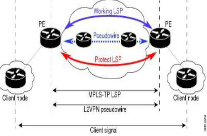
MPLS transport profile (MPLS-TP) LSPs are bidirectional and congruent where LSPs traverse the same path in both directions. An MPLS-TP tunnel can be associated with either working MPLS-TP LSP, protect MPLS-TP LSP, or both.
The working LSP is the primary LSP backed up by the protect LSP. When a working LSP goes down, protect LSP is automatically activated. In order for an MPLS-TP tunnel to be operationally up, it must be configured with at least one LSP.
B. OAM
MPLS-TP has a robust and a transport-like operations and management (OAM) capabilities. It permits guaranteed service level agreements (SLAs), defines protection switching and restoration, enables efficient fault localization, continuity and connectivity verifications, and provides Quality control capabilities and multiservice provider service offerings. MPLS support three kind of OAM: Hop-by-hop (e.g. control plane based), Out-of-band OAM (e.g. UDP return path) and In-band OAM (e.g. PW Associated Channel ACH). The last model (PW ACH) is adopted by MPLS-TP and generalized to LSPs and sections level. The OAM packets can than run in-band, share the same path of user traffic, operate on a per-domain basis and/or across multiple domains, and are able to be configured in the absence of a control plane. The Associated Channel (ACh) is known as technique for in-band Virtual Circuit Connectivity Verification (VCCV) applicable only for Pseudo wires, the LSPs have no mechanism to differentiate user packets from OAM packets. Within MPLS-TP, the ACh is extended to the Generic Associated Channel (G-ACh) and a new label is introduced G-ACh Alert Label (GAL) to identify packets on the G-Ach.
III.LINEAR PROTECTION WITH PSC SUPPORT
The Multiprotocol Label Switching (MPLS) Transport Profile (TP) enables you to create tunnels that provide the transport network service layer over which IP and MPLS traffic traverse. Network survivability is the ability of a network to recover traffic deliver following failure, or degradation, of network resources. The MPLS-TP Survivability Framework (RFC-6372) describes the framework for survivability in MPLS-TP networks, focusing on mechanisms for recovering MPLS-TP label switched paths (LSPs). Linear protection provides rapid and simple protection switching because it can operate between any pair of points within a network. Protection switching is a fully allocated survivability mechanism, meaning that the route and resources of the protection path are reserved for a selected working path or set of working paths. For a point-to-point LSPs, the protected domain is defined as two label edge routers (LERs) and the transport paths that connect them. Protection switching in a point-to-point domain can be applied to a 1+1, 1:1, or 1: n unidirectional or bidirectional protection architecture. When used for bidirectional switching, the protection architecture must also support a Protection State Coordination (PSC) protocol. This protocol is used to help coordinate both ends of the protected domain in selecting the proper traffic flow. For example, if either endpoint detects a failure on the working transport entity, the endpoint sends a PSC message to inform the peer endpoint of the state condition. The PSC protocol decides what local action, if any, should be taken. The figure shows the MPLS-TP linear protection model used and the associated PSC signaling channel for state coordination. In 1:1 bidirectional protection switching, for each direction, the source endpoint sends traffic on either a working transport entity or a protected transport entity, referred to as a data-path. If the either endpoint detects a failure on the working transport entity, that endpoint switches to send and receive traffic from the protected transport entity. Each endpoint also sends a PSC message to inform the peer endpoint of the state condition. The PSC mechanism is necessary to coordinate the two transport entity endpoints and implement 1:1 bidirectional protection switching even for a unidirectional failure.
IV.RING PROTECTION
There are two protection architecture mechanisms, that applied to ring topologies, based on SDH specification and have been proposed in various forums to perform recovery of a topological ring network - "Wrapping" and "Steering".
A. Wrapping
need to "wrap" all data traffic around the ring, on an alternate data path, until arriving at the node that is on the opposite side of the fault. When this far-side node also detects that there is a fault condition on the working path, it can identify that the data traffic that is arriving on the alternate (protecting) data path is intended for the "broken" data path. Therefore, again taking a local decision, can wrap the data back onto the normal working path until the egress from the ring segment. Applying this methodology to MPLS, it is possible to wrap the traffic of each LSP around the failed links via a detour tunnel using a different label for each LSP or to wrap all LSPs using a bypass tunnel and a single label.
This protection scheme is simple in the sense that there is no need for coordination between the different LSR in the ring - only the LSRs that detect the fault must wrap the traffic, either onto the wrapped data path (at the near-end) or back to the working path (at the far-end). Coordination of the switch over to the protection path would be needed to maintain the traffic on a co-routed bidirectional LSP even in cases of a unidirectional fault condition.
B. Steering
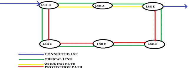
The ring protection mechanism, steering, takes advantage of the ring topology by defining two paths from the ingress point (to the ring) to the egress point going in opposite directions around the ring. This is illustrated in Figure 2, where if we assume that the traffic needs to enter the ring from node B and exit through node F, we could define a primary path through nodes B-A-F, and an alternate path through the nodes B-C-D-E-F. In steering the switching is always performed by the ingress node. If a fault condition is detected anywhere on the working path (B-A-F), then the traffic would be redirected by B to the alternate path (i.e. B-C-D-E-F).
Figure 2: Steering Protection in an MPLS-TP Ring
This mechanism bears similarities to linear 1:1 protection. The two paths around the ring act as the working and protection paths. There is need to communicate to the ingress node the need to switch over to the protection path and there is a need to coordinate the switchover between the two end-points of the protected domain.
V. ACTIVE DYNAMIC PRE-PROTECTION MECHANISM
is in the low-quality or fault state of the work path. In addition, it only keeps the TPP flexibly during the low-quality or fault period.
A. Active Dynamic Pre-Protection Mechanism
The main ideas of the ADPP are as follows:
1. The intermediate node equipped with AFA functions receives the state parameter information from the internal or external performance monitoring components, and judges the information of link and node according to the mapping relationship between the performance parameters and the QoS level of each connection.
2. The intermediate node generates abnormal alarm message to the source and trigger a route flooding, when state value of the corresponding link or node (V) is set to 1.
3. The source node establishes TPP for suffered connections in PW, on receiving abnormal alarm message from the intermediate node.
4. When a fault occurs, the intermediate node would receive the fault state information from monitoring components embedded in it and set V=∞. Then, it will send fault notification message to the source node.
5. The source node switches the suffered connections from PW to TPP on receiving the fault notify message.
6. Return to Step 1. If the fault is relieved, to set V=0, and the normal notification message will be send to the source node, which will switch from TPP to PW and tear down TPP.
VI. COMPARISON ON PROTECTION SCHEMES
Parameter Linear Protection Mechanism
Ring Protection Mechanism Active Dynamic Pre-Protection Mechanism
Protocols Protection state coordination (PSC)
protocol
Coordination protocol ReSerVation protocol-traffic engineering (RSVP-TE) protocol or Open Shortest Path First Traffic Engineering (OSPF-TE) protocol
LSP Path Selection Weighted Shared Risk Link Groups (WSRLG)
Weighted Shared Risk Link Groups (WSRLG)
Active Dynamic Pre-Protection
Utilization Rate of Resources
High High Low
Blocking Rate Of Protection Paths
High Medium Low
Control Plane Load Medium Medium High
VII. CONCLUSION
paths that traverse a ring within an MPLS network can be provided by applying an appropriate instance of linear protection. The active dynamic pre-protection mechanism (ADPP) will provide new alternatives for the diversity of QoS services. It is greatly different from the 1+1 or 1:1 traditional linear protection mechanism from the perspective of time, because the new ADPP scheme can establish the so called temporary protection path before the fault occurs based on the AFA functions. Then it allows switch to TPP immediately when failure occurs. This new mechanism can achieve better efficiency of resources utilization and flexibility when compared with traditional ones.
REFERENCES
[1]. Makoto Murakami And Yoshinori Koike, Highly Reliable And Large-Capacity Packet Transport Networks: Technologies, Perspectives, And Standardization, Journal Of Lightwave Technology, Vol. 32, No. 4, February 15, 2014, 805—816.
[2]. Bai Huifen, Ji Yuefeng, Active dynamic pre-protection mechanism for MPLS-TP network, High Technology Letters, Vol.17, No.4, Dec. 2011, 354--359.
[3]. Y. Weingarten, D. Ceccarelli, D. Caviglia et al., Applicability of MPLS-TP Linear Protection for Ring Topologies, ZTE Corporation April 29, 2013. [4]. Turner S. Bryant, N. Sprecher, et al., MPLS-TP Linear Protection, Nokia Siemens Networks July 26, 2010.