*
Progress and prospect of true steady state operation with RF
Jean Jacquinot1,*1IRFM CEA Cadarache 13108 Saint Paul lez Durance, France
Abstract. Operation of fusion confinement experiments in full steady state is a major challenge for the development towards fusion energy. Critical to achieving this goal is the availability of actively cooled plasma facing components and auxiliary systems withstanding the very harsh plasma environment. Equally challenging are physics issues related to achieving plasma conditions and current drive efficiency required by reactor plasmas. RF heating and current drive systems have been key instruments for obtaining the progress made until today towards steady state. They hold all the records of long pulse plasma operation both in tokamaks and in stellarators. Nevertheless much progress remains to be made in particular for integrating all the requirements necessary for maintaining in steady state the density and plasma pressure conditions of a reactor. This is an important stated aim of ITER and of devices equipped with superconducting magnets. After considering the present state of the art, this review will address the key issues which remain to be solved both in physics and technology for reaching this goal. They constitute very active subjects of research which will require much dedicated experimentation in the new generation of superconducting devices which are now in operation or becoming close to it.
1 Introduction
In the past decades, emphasis of fusion research has been placed on demonstrating, albeit during short pulses, plasma parameters required, at least in dimensionless form, by future fusion reactors. In particular, the world tokamak community has adopted a “wind tunnel” approach which has led to dimensioning the ITER tokamak for achieving, with high confidence, a fusion gain Q = 10 lasting in excess of 300 seconds. This approach left the goal of running in true steady state or at least during very long pulses as an objective to be achieved later in a second phase. This steady state objective has now become a first priority and accordingly the new generation of national machines is conceived with super conducting magnets with the stated aim to be operating in steady state. These new devices are already operating (EAST, KSTAR, SST1, W7X and very recently WEST) or will operate in the near future (JT60-SA).
Several excellent review papers address the physics and technical challenges of steady state operation in reactor relevant conditions. An early paper draws the attention [1] that the baseline tokamak “Elmy H-mode” would require far too much external current drive power which would result in too much recirculating power in a reactor. A large fraction of self-generated bootstrap current is mandatory for a steady state tokamak reactor. A comprehensive physics basis is provided in a recent review [2]. It puts the emphasis on the profound coupling between MHD stability, bootstrap current,
transport and edge plasma conditions and shows the narrow way forward towards a steady state tokamak. Chapter 6 of the Progress in the ITER physics basis [3] reviews the situation for ITER. It considers two target scenarios in addition to the baseline Elmy H-mode for ITER operating either in a hybrid mode (meaning with some remaining inductive drive) of 1000 s or in a non-inductive steady state mode lasting more than 3000 s.
In this paper we first consider recent integrated attempts to steady state achieved to date by the fusion community. We then review the progress made by the actuators based on waves in the electron cyclotron (EC), the ion cyclotron (IC) and the lower hybrid (LH) range of frequencies both in their technical realization and for their properties for driving plasma current. We include using combined operation of neutral beam (NB) and RF systems. Finally we outline the major issues which need to be resolved in line with the ITER programme.
energy extracted from the discharge. For the second category one can choose, for tokamaks, a fusion figure of merit, G, to be maintained for at least several current diffusion times. Here we use G defined as [2, 3]:
G=H89βN /(q95)2 (1) With βN= β/(Ip/aBT); β = <P>/(B2/2μ0) (2) A discharge running in a small or medium size tokamak with a high value of G would extrapolate to a high fusion gain in a tokamak scaled up to the size of ITER or DEMO and operating with the same dimensionless parameters except ρ*. For instance G = 0.3 for the Q = 5 steady state scenario foreseen in ITER.
2.1. The long duration approach
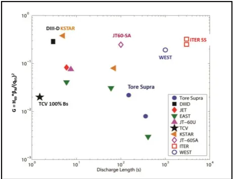
Figure 1 shows some experimental results of steady state operation of fusion devices in terms of energy extracted versus pulse length and figure 2 represents the same data in terms of G versus pulse duration.
Fig. 1. Energy versus duration for steady state operation in recent fusion devices operating with zero loop voltage. The TCV point (black star) refers to a 100% bootstrap current discharge. Open symbols refer to targets set for WEST and the ITER steady state scenarios.
The largest extracted energy of 1.6 GJ has been reached in the stellarator LHD and durations in excess of 5 hours was obtained in the tokamak TRIAM. Tore-Supra holds the record of the highest energy extracted in a tokamak. These records have been achieved in devices equipped with super-conducting magnets potentially allowing of CW plasma operation but, interestingly, in these cases the duration was not limited by the capability of some components of the machine but by unexpected events such as a radiation collapse triggered by detached flakes (LHD), very low frequency oscillations (TRIAM) or MHD events (Tore-Supra).
The ability to operate with Vloop strictly zero and
without any core particle source using RF systems opens the possibility to reveal new physics. For example the neo-classical Ware particle pinch vanishes in these
conditions. Nevertheless the Vloop = 0 Tore Supra
experiments [4] reveal moderately peaked density profiles corresponding to a turbulent inward pinch which would, if present in ITER, provide a significant gain in Q values on the order of 30%.
2.2 The fusion performance approach
Fig. 2. The fusion figure of merit G versus duration for steady state operation in recent fusion devices operating with zero loop voltage. The TCV point (black star) refers to the 100% bootstrap current discharge. Open symbols refer to targets set for JT60-SA, WEST and the ITER steady state scenarios.
When the data of figure 1 is now plotted with respect to the fusion figure of merit G, the high performance steady state discharges (DIII-D, KSTAR) are now seen to match the G requirement for ITER but the duration is short by 3 orders of magnitude. Nevertheless, as discussed below, they stand as the most promising approach to steady state for tokamaks. Also quite remarkable but for a different reason, is the TCV point [5] which corresponds to a fully non inductive plasma despite avoiding the use of any external current drive. It shows that auto generated plasma currents (the bootstrap current) can reach 100% of the plasma current and maintain the configuration in steady state. Furthermore, it demonstrates that the bootstrap current profile can be exactly and stably aligned with the high gradient region it engenders; this auto regulation process is remarkable and will also be seen in the section 2.3 dealing with the hybrid discharges.
Let us now recall that the bootstrap current fraction αBS is proportional to the poloidal pressure βp and can
written as:
αBS∝βp∝βNB/I = CBSβNq95 (3) As already mentioned in the introduction αBS should
be large in a steady state tokamak reactor (say > 0.6) in order to avoid excessive external current drive power. Comparing equations 1 and 3 and wanting to realize large values of both G and αBS, we are faced with the
The 100% TCV discharge does realize good normalized confinement at very high q95 thanks to an ITB (Internal Transport Barrier) resulting from a reverse magnetic shear configuration. However the q95 is far too high for achieving a reactor relevant fusion performance. The next section shows how to remedy this at the expense of a lower αBS which is still quite acceptable.
2.3 Realizing both high G and high αBS
Reactor/ITER relevant steady state plasmas require high values of both G and αBS. Modern tokamaks (Asdex-Upgrade, DIII-D, JET, JT60-U and KSTAR) have demonstrated this by realizing simultaneously high values of H89 and βN while keeping q95 rather large in order to keep at a low level the requirement for external current drive.
The limit of βN is set by ideal MHD stability. Neglecting the influence of the walls and with an ITER like configuration this limit is close to 3.5 (the ‘no-wall limit’). With broad plasmas close enough to the walls and/or with feedback stabilization this can be extended to values approaching 5, the ‘wall-limit’. H89, the confinement H-mode factor, which reaches a value of 2 in the standard elmy H-mode thanks to a confinement barrier forming in the plasma periphery can be increased further by proper tailoring of the plasma current density profile.
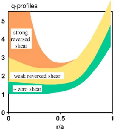
Fig. 3. Profiles of the safety factor q leading to improved confinement in the plasma core. Reproduced from [3]
An important consideration for improving the core confinement is to avoid the existence in the plasma of low rational numbers of q which can sustain major MHD instabilities such as 1/1 leading to sawteeth or 3/2 leading to NTM (neo classical tearing modes). When this is achieved, it is observed that reversed, weak or nearly zero central shear profiles generates high core confinement.
Highly reversed shear produces a very strong localized confinement barrier which in turn creates a significant bootstrap current. A spectacular example of such a regime is the JET D/T shot [6] where the ion temperature reached 40 keV and the fusion power 8 MW. However MHD stabilities with such a steep pressure gradient do not allow reaching a high value of βN which was limited to 1.9 in the JET case before going unstable. Therefore such a scenario does not seem particularly well suited to steady-state operation for fusion energy.
On the contrary stable plasmas with βN values reaching 3.5 were obtained in weak central shear regimes were the minimum value of q, qmin, is raised either slightly above 1 or even above 1.5.
2.3.1 The ‘hybrid’: a scenario with weak central shear and qminslightly above 1
The so-called hybrid scenario involves a weak central shear and qmin slightly above 1. It has been pioneered by the Asdex-Upgrade team [7], reproduced with variants in most other tokamaks and developed on DIII-D [8] to be shown compatible with the planned Q=5 ITER steady state scenario.
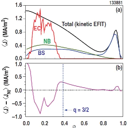
Fig. 5. Current drive sources in a hybrid discharge in DIII-D. ECCD overdrives the central part of the current but poloidal magnetic flux pumping manages to distribute the current across the profile in a stable way. Reproduced from [8].
Initially, the term ‘hybrid’ was given to suggest that inductive discharges could, thanks to a large bootstrap fraction, be lengthened significantly whilst not being fully steady state. It now turns out that, with proper optimisation, they could well become fully non-inductive as shown on figures 4 and 5 which give their peculiar characteristics. The heating and current drive systems are started before the ohmic current has fully penetrated in the plasma centre. Therefore the safety factor q is above 1 everywhere, sawteeth are absent and the current profile is broad which is favourable for MHD stability. This configuration becomes frozen by programming the H&CD systems for maintaining null the loop voltage (figure 4). Note that ECCD overdrives the central current density. Nevertheless qmin keeps hovering slightly and stably above 1. A weak 3/2 NTM is detected. This mode has a minute effect on energy confinement but seems to be responsible for maintaining a stable current profile and energy confinement. The use of ECCD near the centre offers the benefit of good current drive efficiency and there is no need to align the current sources.
This mode is resilient to both ELM mitigation using RMP coils (figure 4) and to enhancing radiation in the divertor using argon injection [8] as would be required in ITER. It has also been demonstrated recently in Asdex-Upgrade equipped with tungsten plasma facing components (figure 6, [9]).
Fig. 6. A raised qmin quasi steady state discharge in Asdex-Upgrade equipped with tungsten PFC. The contributions to the plasma current are in grey for ohmic, yellow from bootstrap red from the beams and blue from EC. Courtesy of S. Bock
2.3.2 The raised qminaround 1.4
It is also possible [10] to achieve similar results without having to rely on the somewhat miraculous action of the weak 3/2 mode which also takes its toll by reducing the global energy confinement time by some 10%. In this case, significant external off-axis current drive needs to be available and is programmed to maintain qmin around 1.4 where optimum results are obtained. A broad pressure profile is obtained which is favourable to MHD stability thanks to the proximity of the walls. Therefore this mode offers more stability margin than the previous one but requires off-axis current drive power. ECCD and NBCD (neutral beam current drive) become notoriously inefficient the further you go off-axis. The use of LHCD (Lower Hybrid Current Drive) for the off-axis drive would be well adapted to this (section 3.3).
3 The RF actuators
If all the longest discharges have been obtained with RF systems only, the discharges with the highest values of G values have all been obtained with neutral beams as a work horse complemented by some RF power. In present day machines, the beams have the advantage of heating mainly the ions and of injecting torque and particles. However these 3 properties will not extrapolate to ITER conditions and even less to a reactor. One has to wonder if the nice results just reported will carry over in ITER when fusion born alpha particles will be the main heat source and with a much increased role of RF systems. It is therefore a priority to demonstrate equivalent scenarios using mainly RF systems. Let us consider them in turn.
3.1. ECRH and ECCD
breakdown, highly localised heating and current drive and control of sawteeth and NTMs. No wonder, they are tools highly sought after in fusion research. However they involve advanced hardware (gyrotrons, diamond windows, long transmission lines) which can be delicate and costly.
Fig. 7. The three 170 GHz gyrotrons developed for ITER by Russia, Japan and EU. The maximum power and pulse duration obtained during tests are indicated. Reproduced from [11].
Figure 7 shows the three gyrotrons [12, 13, and 14] which have been developed for ITER and the performance in duration and power reached so far. They are well on the way to reaching the ITER specifications (pulse length of 3600 s, 1MW at window with ≥95%
TEM00 mode purity, LHe free cryogenic magnets, >50% efficiency (Pout/Pin)). Some designs still have to face the challenges of mass production, high reliability, higher power (≥1.0MW), long life (≥5 years) and resilience to external magnetic fields (0.1mT < |Br| < 0.25mT). Research in the field of gyrotrons is very active and making progress towards higher power units and the capability of operating at several different frequencies with the same tube [13].
The W7-X stellarators is not yet ready for true steady state operation with RF but its 140 GHz 1000 s system is fully commissioned for operating in this way when required [15]. It includes actively cooled steerable mirrors and interlocked systems for protecting against
stray microwave radiation which could damage in-vessel components such as cryo-pumps. It is also worth noting the development of a remote steering capability of the EC beams [16] which offers a simple and compact solution.
3.2. ICRH and ICCD
Despite obvious constraints of having to couple through an evanescent zone at the plasma edge, ICRH and ICCD (Ion cyclotron Resonance Heating and Ion Cyclotron Curent Drive)) are toolsLHCD of choice in modern tokamak research. Used with good success on the D/T programs of both JET and TFTR [17], the method extrapolates well to large D/T plasmas such as ITER where temperature and size guarantee single–pass damping in several scenarios and the broad frequency bandwidth of the entire system allows interacting with electrons or a chosen ion species.
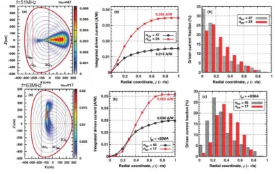
This property can be used, not only for localised heating but also in steady state tokamak scenarios to drive current either close to the plasma axis with an
equatorial launcher or around ρ = 0.3 with a launcher located on the top of the machine (figure 8). Although modest, the current drive efficiency is the best one can do with any external central CD system for instance with NBCD at 1.5MeV [18] because the plasma electrons receive directly parallel energy from TTMP and Landau damping. We will see later that LHCD can also give an even more competitive CD efficiency but its use in ITER-size machines is restricted to a far off axis contribution.
Fig. 8. ICCD for DEMO plasmas with 2 different locations of IC antennas. The 3 graphs on the top row corresponds to the equatorial launcher and compares the efficiency and the current profile of 2 toroidal mode numbers 47 and 24. The 3 graphs on the bottom row corresponds to the top launcher and compares the efficiency of the toroidal mode numbers 45 and 17 The upper launcher gives the
best CD efficiency of 0.052 A/W. Reproduced from [18].
3.3. LHCD
Historically, the first demonstration of steady state operation of a tokamak without any inductive drive for more than 3 s was made with lower hybrid waves launched in PLT [25]. In small or medium size devices LHCD has the clear advantage over all the other methods that the waves can damp most their energy to super-thermal electrons which, because of their reduced drag, provides a very effective way to drive current. LHCD antennas are made of multiple waveguides (figure 9) each being phased to launch, with high directivity, traveling waves with a parallel index of refraction chosen to be high enough for providing accessibility (N|| >N||a ≈ ωpe/Ωce ∝√ne/B) but small
enough to couple to fast electrons carrying the current. In
small or medium size devices, typically N// equals 1.4 to
3 and supra-thermal electrons are in the range of 30 to 120keV. The waves can travel a long way in the plasma before being damped and during this process undergo an up-shift of the index of refraction (figure 10). A quasi-linear plateau in the electron distribution function is created leading to the formation of the super-thermal population. Detailed comparisons between theory, simulation and experiments [27] show good agreement provided the most accurate description of the wave ray-tracing propagation and the relativistic effects in the quasi-linear interaction are taken into account. It also seems necessary [27] to assume that a tail in the N//
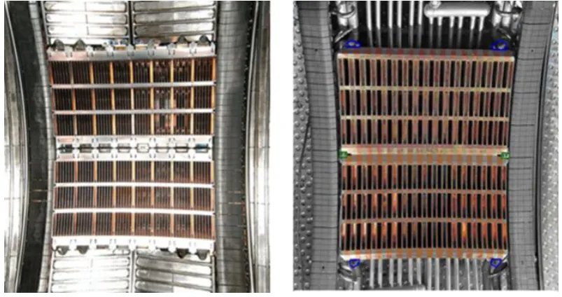
Fig. 9. Two types of LHCD launchers used in Tore-Supra and installed in WEST: Left: FAM, all wave guides are powered and phased using a multijunction. Right: PAM, waveguide are alternately active and passive to ease active cooling. These modules are rated for a total of 7 MW 1000s operation [28, 29].
Fig. 10. Illustration of the N||upshift, occurring during propagation in the plasma or near the antenna. It closes the spectral gap so that the waves launched at N//0 can couple to fast electrons. Left: The launched wave spectrum N//0 brodenned to N//L. Right and in
blue: The electron distribution functions before application of the RF (log(f0) and after (log (f). Reproduced from [26].
In large, dense and hot plasmas such as ITER, N||a ,
the minimum refraction index of waves which can access to the plasma, increases and N||L (6.5/√Te [keV]), the
refraction index coupling to thermal electrons, becomes close to N//0 the index launched by the antenna. We are
now in a different situation of single pass damping driving current far off-axis without creation of very fast electrons; best results from simulations of the current drive efficiency are obtained [30] with an index close to N// = 1.9.
Figure 9 illustrates actively cooled LHCD launchers capable of launching in Tore Supra 3 to 4 MW per port for 1000 s. The LH waves do not propagate in vacuum and have to tunnel through a cut-off layer. Nevertheless, it is possible to couple at about 10 cm from the plasma using gas puffing in the vicinity of the launcher.
Klystrons and sometimes gyrotrons provide the power sources in frequencies ranging from 2.45 GHz to 8 GHz. For instance, Tore-Supra/WEST can use 16 klystrons at 3.7 GHz capable of delivering 9.2 MW for 1000 s. These klystrons are not, at present, using a depressed collector and their efficiency is only 37.5%. Recent developments have led to availability of 4.6 GHz systems used on Alcator C-mod and EAST and 5 GHz systems intended for KSTAR and ITER [31, 32].
4 Steady state operation of ITER
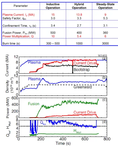
Table 1. The ITER design basis scenarios.
Fig. 11. Scaling of the DIII-D discharge (figure 4) to ITER’s R and magnetic field with fixed dimensionless parameters except ρ*. Note that the current relaxation time τRextrapolates from 1.9 s to 245 s in ITER. Reproduced from [8].
The hybrid scenario plans is based on the hybrid mode of operation described in section 2.2.1. Long burn times of 1000 s are expected from a discharge sustained by a high bootstrap current supplemented by the external current supplied by the ITER H&CD systems not far from the axis and by some remaining inductive current. Figure 11 shows that the high G discharges discussed in figure 4 would indeed extrapolate well to the ITER conditions with the same dimensionless parameters except ρ*. The extrapolation matches the gain Q and the fusion power
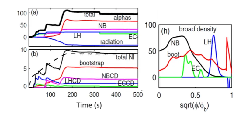
Fig. 12. Simulation of the full steady state operation in ITER using 33 MW of NB, 20 MW of both EC and LH. Left: power and plasma current traces during the setting-up phase (first 500s). Right: profiles of the currents generated by bootstrap, NB, EC and LH. It is found that the 20 MW of LH is necessary to broaden the profile ensuring both high βN stability and high confinement.
The third scenario, steady state operation, reduces further the plasma current and the fusion power to ensure that full non inductive operation is possible. However the target gain (Q = 6) remains significant which requires an excellent normalized confinement at high βN.
We have seen in section 2.2.2 that this can be achieved with qmin raised at about 1.4 which requires off-axis
current drive in order to broaden the current profile. Recently, the current diffusive ballooning mode (CDBM) model has been used to simulate steady state operation of ITER [33]. This model simulates, in particular, the formation of ITBs resulting from a vanishing local shear. Figure 12 gives the results of a simulation for ITER. It is shown that the combination of EC and LH waves is an effective combination for this mode of operation. ECCD at mid radius prevents the bootstrap current from peaking and LHCD ensures that the current profile remains broad. These very interesting results should however be seen from the perspective that CDBM has not yet been benchmarked against the international ITB data base and that there are some doubts that the GENRAY code used in this simulation accounts correctly to the LH physics at high density.
5
Conclusions
Operation in true steady state has now become a major research area in fusion research. Although no experiments have yet been able to combine simultaneously ITER-long pulses and high performance, it is apparent from this review that considerable progress has been made on the many aspects, sometimes conflictual, which have to be integrated for reaching the goal.
New modern devices equipped with CW components (super-conducting magnets, active cooling of all in vessel components, RF power sources and controls) are now operational or coming into operation.
New steady state records are around the corner. In what area would they matter most?
We have noted the gap between the high G discharges dominated by NB but only capable so far of relatively short pulses and the very long pulse discharges dominated by RF with low G values. Bridging this gap should receive a high priority; it would demonstrate the successful integration of the core/edge plasma constraints with the plasma/wall interactions operating in complete active cooling conditions. Doing it with RF only, with low torque and no direct ion heating, would be particularly ITER and reactor relevant.
A major recent advance is without doubt the experimental demonstration by nearly all large tokamaks of stable high performance discharges with qmin raised
above 1 and with low central shear. They provide high performance and a high bootstrap current fraction. They extrapolate well to the ITER secondary goal of extended burn and provide a path towards a reactor running in steady state with a tolerable recirculating power devoted to external current drive. The documentation of this scenario by an international data base is of great value.
The author would like to acknowledge gratefully the information and advices provided by many colleagues especially from: B. Beaumont, V. Bobkov, G. Denisov, A. Ekedahl, R. Ikeda, E. Joffrin, M. Goniche, Ph. Lamalle, T. Luce, A. Mukherjee, J.-M. Noterdaeme, Y. Peysson, D. Van Ester, W. Zhang.
References
1. J. Jacquinot, V.P. Bhatnagar, C. Gormezano and the JET Team, Plasma Phys. Control. Fusion 35 A35 (1993)
2. T.C. Luce, Physics of Plasmas 18, 030501 (2011); doi: 10.1063/1.3551571
3. C. Gormezano et al. Nucl. Fusion 47 S285–S336 (2007)
4. G.T. Hoang, Phys. Rev. Lett. 90 1555507 (2003) 5. S. Coda, O. Sauter, M. A. Henderson, and T. P.
Goodman, Proceedings of the IAEA Fusion Energy
Conference (2008)
6. C. Gormezano et al. Phys. Rev. Lett. 80, 5544 (1998)
7. A. C. C. Sips, Plasma Phys. Control. Fusion 44 B69–B83 (2002)
8. C. C. Petty et al. Nucl. Fusion 56 (2016) and Proceedings of the IAEA Fusion Energy Conference (2016)
9. S. Bock, submitted to Nucl. Fusion
10. C.T. Holtcomb, Nucl. Fusion 54 093009 (2014) 11. B. Beaumont, ITER Business Forum, March (2017) 12. G.G. Denisov and A.G. Litvak FIP/1-6Ra,
Proceedings of the IAEA Fusion Energy
Conference (2016)
13. R. Ikeda et al. FIP/1-6Rb Proceedings of the IAEA
Fusion Energy Conference (2016); see also this
conference (2017)
14. S. Bethuys, this conference (2017)
15. H.-S. Bosch and H. Laqua, private communication; T. Stange, this conference (2017)
16. B. Plaum et al. J. Phys. Conference Series 25 84-91(2005)
17. J. Jacquinot and the JET team, Plasma Phys. Control. Fusion 41 A13 (1999)
18. Y. Kazakov, D. Van Ester et al. Plasma Phys. Control. Fusion 57 025014(2014)
19. A. Mukherjee et al, Proceedings of the IAEA Fusion
Energy Conference (2016)
20. C. Bourdelle et al. Nucl. Fusion 55 063017 (2015) 21. D. D’Ippolito, J. Myra, M. Bures and J. Jacquinot,
Plasma Phys. and Control. Fusion 33 607 (1991). 22. L. Colas et al. Phys. Plasmas 19 052505 (2012); L.
Colas review paper at this conference (2017) 23. M. Bures, J. Jacquinot, M. Stamp, D. Summers, D.
Start, T. Wade, D.A. D'Ippolito and J.R. Myra, Nucl. Fusion 32 1139 (1992)
24. V. Bobkov et al, Plasma Phys. Control. Fusion 59 014022 (2017)
25. S. Bernabei et al., Phys. Rev. Lett. 49, 1255 (1982) 26. Y. Peysson et al. 42nd EPS conf. Lisbon (2015) 27. Y. Peysson et al. Plasma Phys. Control. Fusion 58
044008 (2016); see also Y. Peysson et al. invited
paper at this conference (2017)
28. A. Ekedahl et al., Nucl. Fusion 50 112002 (2010) and A. Ekedahl et al. Proceedings of the IAEA
Fusion Energy Conference (2016)
29. M. Goniche et al. Physics of Plasmas 21 061515 (2014)
30. J. Decker et al.,Nucl. Fusion, 073025 (2011) 31. J. Hillairet et al. Fusion Engineering and Design 94
22-30 (2015)