NUMERICAL SOLUTION OF A FLOW INSIDE A LABYRINTH SEAL
Jan ŠIMÁK*, Petr STRAKA,Jaroslav PELANT
Abstract: The aim of this study is a behaviour of a flow inside a labyrinth seal on a rotating shaft. The labyrinth seal is a type of a non-contact seal where a leakage of a fluid is prevented by a rather complicated path, which the fluid has to overcome. In the presented case the sealed medium is the air and the seal is made by a system of 20 teeth on a rotating shaft situated against a smooth static surface. Centrifugal forces present due to the rotation of the shaft create vortices in each chamber and thus dissipate the axial velocity of the escaping air.The structure of the flow field in-side the seal is studied through the use of numerical methods. Three-dimensional solution of the Navier-Stokes equations for turbulent flow is very time consuming. In order to reduce the computational time we can simplify our problem and solve it as an axisymmetric problem in a two-dimensional meridian plane. For this case we use a transformation of the Navier-Stokes equations and of the standard k-omega turbu-lence model into a cylindrical coordinate system. A finite volume method is used for the solution of the resulting problem. A one-side modification of the Riemann prob-lem for boundary conditions is used at the inlet and at the outlet of the axisymmetric channel. The total pressure and total density (temperature) are to be used preferably at the inlet whereas the static pressure is used at the outlet for the compatibility. This idea yields physically relevant boundary conditions. The important characteristics such as a mass flow rate and a power loss, depending on a pressure ratio (1.1 - 4) and an angular velocity (1000 - 15000 rpm) are evaluated.
1
I
NTRODUCTIONThe aim of this study is to investigate a behaviour of a flow inside a labyrinth seal and evaluate its characteristics such as a mass flow rate and a power loss. The labyrinth seal is a type of a non-contact seal where a leakage of a fluid is prevented by a rather complicated path, which the fluid has to overcome. In the presented case, we study a seal attached to a rotating turbine shaft, which is a part of an experimental device. The sealed medium is an air and the labyrinth seal is made by a set of twenty teeth situated on the rotating shaft against a smooth static surface. Centrifugal forces present due to the rotation of the shaft create vortices in each chamber and thus dissipate the axial velocity of the escaping air.
2
N
UMERICAL MODELThe flow of the air through the seal is described by a system of the RANS equations combined with a
k–ωturbulence model [1, 5]. The form of the equations for a mean value variables is the following:
∂ρ
∂t + div (ρv) = 0, (1)
∂ρvi
∂t + div (ρviv) = div (T)i, i= 1,2,3, (2) ∂E
∂t + div (Ev) = div (Tv)−divq. (3)
We use a standard notation here, the stress tensorT is defined by
T = (−p+λdivv)I+ 2μD, (4)
* Výzkumný a zkušební letecký ústav, a.s., Beranových 130, 199 05 Praha 9 - Letˇnany, Czech republic, [email protected]
whereD, a strain rate tensor, is given byD= 1/2∇v+∇vT.
Taking into consideration the geometry of our problem, it is really natural to use cylindrical coordinates, which simplify the description of the problem. The Cartesian coordinates(x, y, z)are then transformed to a new coordinate system(h, r, ϕ),
h=x,
r=y2+z2, (5)
ϕ= arctan(z/y).
The inverse coordinate transformation can be, of course, expressed as
x=h,
y=rcosϕ, (6)
z=rsinϕ.
A transformation of a vector will be of the form
(u, v, w) = (ur, vrcosϕ−wrsinϕ, vrsinϕ+wrcosϕ). (7)
It is possible to show that the gradient expressed in cylindrical coordinates is of the form
∇f =
∂f ∂h, ∂f ∂r, 1 r ∂f ∂ϕ (8)
and that the divergence of a vector in the new system is
divv= ∂ur
∂h + ∂vr ∂r + vr r + 1 r ∂wr
∂ϕ. (9)
The flow inside the seal can be assumed axisymmetric so the derivatives in the ϕ direction can be neglected. Thus the third space variable is eliminated from the system and we can solve our problem in a two-dimensional plane section along the axis. In the following text, we will deal only with cylindrical coordinates. The notations xi andvi denote components of a space and a velocity vector, now with respect to the new coordinates.
After some rearrangements, the equations (1) – (3) can be written in the form of
∂ρ ∂t + 2 j=1 ∂ρvj
∂xj + ρv2
x2 = 0, (10)
∂ρvi
∂t +
2
j=1
∂(ρvivj+δijp)
∂xj + (1 +δi3) ρviv2
x2 −δi2 ρv2
3 x2 =
2
j=1 ∂τˆij
∂xj + (1 +δi3) ˆ τi2 x2 +δi2
ˆ τ33
x2,
i= 1,2,3, (11)
∂E ∂t +
2
j=1
∂(E+p)vj
∂xj +
(E+p)v2
x2 =
2 j=1 ∂ ∂xj 3 k=1 ˆ
τjkvk+κ
μ Pr+ μT PrT ∂e
∂xj +
+1 r 3 k=1 ˆ
τ2kvk+κ
μ Pr+ μT PrT ∂e
∂x2 . (12)
Thek–ωturbulence model is of the form
∂ρk ∂t + 2 j=1 ∂ρkvj
∂xj + ρkv2
x2 = ˆPk−β
∗ρωk+2
j=1 ∂ ∂xj
(μ+σkμT) ∂k ∂xj
+1
r(μ+σkμT) ∂k
∂x2, (13)
∂ρω ∂t + 2 j=1 ∂ρωvj
∂xj + ρωv2
x2 = ˆPω−βρω 2+2
j=1 ∂ ∂xj
(μ+σωμT) ∂ω ∂xj
+1
r(μ+σωμT) ∂ω
The above mentioned system of partial differential equations is solved by an implicit finite volume method on a structured grid. As a boundary condition for an inlet part of the boundary, we prescribe a total temperature and a total pressure. On the outlet part of the boundary, a static pressure is prescribed. To obtain proper values of state variables on a boundary edge, located on the inlet or outlet boundary, a modified 1d Riemann problem is solved. The formulation of this representation of boundary conditions can be found in [2].
3
RESULTS
The numerical method is validated on a smooth cylinder rotating around its axis and the computed moment is compared with values obtained by Theodorsen [4]. Even though the flow is not exactly axisymmetric due to the presence of instabilities in a boundary layer, the model is sufficiently precise for our purpose. Moreover, in cases with a pressure gradient present, these effects are diminished and thus do not spoil the results.
3.1 VALIDATION ON A SMOOTH CYLINDER
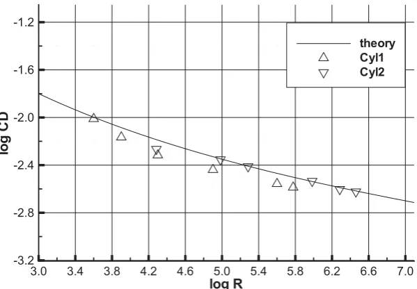
The problem of a drag of a revolving cylinder was extensively studied in the past and many experimental results can be found in the literature. The drag coefficient for a revolving cylinder, which is equal to a moment coefficient, is given by
CD =qSrM , (15)
whereM is a moment acting on the cylinder, q is a dynamic pressure (defined by q = 1/2 ρω2r2),
S is a surface of the cylinder and r is a radius. The symbol ω will denote an angular velocity. The theoretical drag coefficient for a turbulent flow can be expressed as a function of the Reynolds number
R(R=ρωr2/μ),
1
√
CD =−0.6 + 4.07 log10
RCD
. (16)
The Figure 1 shows a theoretical prediction and evaluated values for two cylinders, differing in a diameter
rand a lengthl. The comparison with measurements presented in [4] shows a quite good agreement.
log R
lo
g
C
D
3.0 3.4 3.8 4.2 4.6 5.0 5.4 5.8 6.2 6.6 7.0 -3.2
-2.8 -2.4 -2.0 -1.6 -1.2
theory Cyl1 Cyl2
3.2 SHAFT SEAL
The rotating turbine shaft is sealed by a labyrinth seal, which is made of twenty teeth. The plane section is depicted in the Figure 2. The total length of the seal is 117 mm and the smallest gap is 0.5 mm. The air is entering the seal through a narrow gap from the left and leaving it on the right side. Due to a large opening of the seal, there is a recirculation across the outlet boundary. As an inlet boundary condition, a total temperatureT0= 20°C and a total pressure p0in the range of40–130kPa are prescribed. The results were computed for different back pressure ratiosp0/p1 in the range of1.1– 4.0 and for design regimes between1000–15000revolutions per minute.
0 0.02 0.04 0.06 0.08 0.1
0.16 0.165 0.17
Figure 2: The geometry of a plane section of the shaft seal
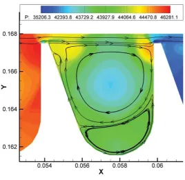
The structure of the flow inside a cavity is shown in the Figure 3. The vortices are caused by centrifugal forces and by the geometry of the rotating lower wall. Also it is clearly seen a pressure drop between cavities.
Figure 3: Pressure distribution in a cavity and streamlines
p0/p1
M
1 2 3 4
0 0.2 0.4 0.6 0.8 1 1.2 1.4 40kPa, 1000rpm 40kPa, 5000rpm 40kPa, 15000rpm p0/p1 M
1 2 3 4
0 0.2 0.4 0.6 0.8 1 1.2 1.4 60kPa, 1000rpm 60kPa, 5000rpm 60kPa, 10000rpm 60kPa, 15000rpm p0/p1 M
1 2 3 4
0 0.2 0.4 0.6 0.8 1 1.2 1.4 1.6 1.8 2 2.2 100kPa, 1000rpm 100kPa, 5000rpm 100kPa, 10000rpm 100kPa, 15000rpm p0/p1 M
1 2 3 4
0 0.2 0.4 0.6 0.8 1 1.2 1.4 1.6 1.8 2 2.2 130kPa, 1000rpm 130kPa, 7500rpm 130kPa, 10000rpm
Figure 4: The moment [Nm] acting on the shaft as a function of the pressure ratiop0/p1
p0/p1
Q
1 2 3 4
0 0.005 0.01 0.015 0.02 0.025 0.03 40kPa, 1000rpm 40kPa, 5000rpm 40kPa, 15000rpm p0/p1 Q
1 2 3 4
0 0.005 0.01 0.015 0.02 0.025 0.03 60kPa, 1000rpm 60kPa, 5000rpm 60kPa, 10000rpm 60kPa, 15000rpm p0/p1 Q
1 2 3 4
0 0.01 0.02 0.03 0.04 0.05 0.06 0.07 100kPa, 1000rpm 100kPa, 5000rpm 100kPa, 10000rpm 100kPa, 15000rpm p0/p1 Q
1 2 3 4
0 0.01 0.02 0.03 0.04 0.05 0.06 0.07 130kPa, 1000rpm 130kPa, 7500rpm 130kPa, 10000rpm
Figure 5: The leakage of the air [kg/s] through the seal as a function of the pressure ratiop0/p1
rpm
Q
5000 10000 15000 0.01 0.02 0.03 0.04 60kpa,1.1 60kpa,1.4 60kpa,2 60kpa,3 60kpa,4 rpm Q
5000 10000 15000 0.01 0.02 0.03 0.04 100kpa,1.1 100kpa,1.4 100kpa,2 100kpa,3 100kpa,4 rpm Po w e r lo s s
5000 10000 15000 0.5 1 1.5 2 2.5 3 60kpa,1.1 60kpa,1.4 60kpa,2 60kpa,3 60kpa,4 rpm Po w e r lo s s
5000 10000 15000 0.5 1 1.5 2 2.5 3 100kpa,1.1 100kpa,1.4 100kpa,2 100kpa,3 100kpa,4
4
D
ISCUSSIONThe mentioned method was used to solve a flow inside a labyrinth seal. The real problem was simplified to an axisymmetric problem, which is very close to the reality. The results are in accordance with the expectations. The advantage of the method is its speed and reasonable computer requirements. Nevertheless, it will be worth comparing obtained results with a full 3d model in the future.
Another problem may be a propagation of a heat, especially in the case of a higher angular frequency. The air is heated by the moving wall and the temperature of the seal is rising. This problem requires a better treatment of boundary conditions on walls, including heat transfer to the surroundings. But in the assumed extent of regimes, this problem is not so noticeable.
REFERENCES
[1] Kok J.C.: Resolving the Dependence on Freestream Values for thek–ω Turbulence Model, AIAA Journal Vol. 38, No. 7, July 2000
[2] Kyncl M., Pelant J.: Applications of the Navier-Stokes Equations for 3d Viscous Laminar Flow for Symmetric Inlet and Outlet Parts of Turbine Engines with the Use of Various Boundary Conditions, VZLU Report R–3998, Prague, 2006
[3] Kyncl M., Pelant J.: Applications of the Navier-Stokes Equations for 3d Viscous, Compressible Lam-inar and Turbulent Flow in the Axis-symmetrical Channels as Parts of Turbine Engines with Steady or Moving Walls, VZLU Report R–4301, Prague, 2007
[4] Theodorsen T., Regier A.: Experiment on Drag of Revolving Disks, Cylinders, and Streamline Rods at High Speeds, NACA Report No. 793, 1944
![Figure 4: The moment [Nm] acting on the shaft as a function of the pressure ratio p0/p1](https://thumb-us.123doks.com/thumbv2/123dok_us/8084102.1348990/5.595.80.520.548.712/figure-moment-nm-acting-shaft-function-pressure-ratio.webp)
