Performance of Pile groups under Combined
Uplift and Lateral Loading
Bhavik Parekh1, S. W. Thakare2
P.G. Student, Department of Civil Engineering, Government College of Engineering, Amravati, Maharashtra, India1 Associate Professor, Department of Civil Engineering, Government College of Engineering, Amravati, Maharashtra,
India2
ABSTRACT: When soil of low bearing capacity extends to a considerable depth, piles are generally used to transmit vertical and lateral loads to the surrounding soil media. Piles that are used under tall chimneys, television towers, high rise buildings, offshore structures, etc. are normally subjected to high uplift loads. These piles or pile groups should resist not only uplift movements but also lateral movements. This paper presents the behaviour of pile groups under combined uplift and lateral loading in sand for various parameters. Experiments were performed to investigate the behaviour of single pile, square pile group and hexagonal pile group under independent lateral, independent uplift, and under combined uplift and lateral loading.Tests were carried out on model piles with length to diameter ratios of 10, 20, 30, and 40. The experimental results indicated that lateral load capacity of single pile and square pile group increases significantly with increase in L/D ratio up to 30, however beyond 30 increase in lateral capacity is marginal. It was found that Lateral load capacity of hexagonal pile group increased almost linearly with increase in L/D ratio from 20 to 40. It was also observed that under combined loading for hexagonal pile group, uplift load capacity increased marginally up to L/D ratio 30. However, beyond 30 increased in uplift capacity was significant. Increase in uplift load acting on pile results in increase in its lateral load capacity and vice versa.
KEYWORDS: Lateral load, Uplift load, Square pile group, Hexagonal pile group. I. INTRODUCTION
Pile foundation belongs to the category of deep foundation. A pile is a slender columnar structure buried inside the earth. It serves to transmit the load to deeper lying firm strata when the soil at shallow depth can’t provide adequate support to the load. According to current practice, piles are independently analyzed first for the vertical load to determine their bearing capacity and settlement and then for the lateral load to determine its lateral load capacity. This approach is valid only for small lateral loads, However, in case of coastal/offshore applications, the lateral loads are significantly high; of the order of 10–20% of the vertical loads and in such cases, studying the interaction effects due to combined vertical and lateral loads is essential. Piles are often constructed in groups and behavior of single pile differs significantly from that of pile group.
The use of pile foundations is increasing day by day due to non-availability of suitable land for construction. Heavy multi-storied building are being constructed, and load from these structures can not be directly transferred to ground due to low bearing capacity issue and stability issues of building during lateral load application. So, demand for use of pile foundations are increasing day by day.The scope of present work was to study experimentally the behavior of pile groups in sandy soil under combined uplift and lateral loading for various parameters.
II. RELATEDWORK
1. Patra and Pise (2001)1 conducted an experimental study on model pile groups of configuration 1× 1, 2×1, 3×1, 2×2 and 3×2 for embedment length-to-diameter ratios L/d = 12 and 38, spacing from 3 to 6 pile diameter, and pile friction angles ϕ = 20° and 31°, subjected to lateral loads, in dry Ennore sand obtained from Chennai, India.. This study concluded that the ultimate lateral capacity of pile group depends on the length-to-diameter ratio of pile, pile friction angle, pile group geometry, spacing of piles in a group, and sand placement density. Pile groups having rough piles offered more resistance than groups with smooth piles.
2. Chandrasekaranet al (2010)2 carried out static lateral load tests on 1×2, 2×2, 1×4, and 3×3 model pile groups embedded in soft clay. Tests were carried out on piles with length to diameter ratios of 15, 30, and 40 and three to nine pile diameter spacing. Group efficiency, critical spacing, were evaluated from the experimental study.This study concluded that percentage reduction in the lateral capacity increased with the number of piles and a maximum reduction in capacity of about 40% was noted for the 3×3 pile group.
3. Sudharani and Rakaraddi (2014)3 conducted an experimental investigation on single pile, group of pile, enlarged based pile, smooth pile, rough pile embedded in sand poured to desired densities by rainfall technique using model pile of solid mild steel, aluminium and wood material 12.7 mm diameter & length 360 mm.This study concluded that the increase in the density of soil increased the load carrying capacity of single and group of pile both in tipped pile and enlarge base pile and safe load carrying capacity of pile was high in enlarge base pile than tipped pile.
4. Shah and Vaniya (2014)4 conducted an experimental study on mono pile with varying embedment length to diameter ratio (L/D) of 4, 6 & 8 length of mono pile being 360 , 540 & 720 mm. This study concluded that for any slenderness ratio high friction mono pile was more efficient than smooth mono pile. As the slenderness ratio of mono pile increased the maximum uplift capacity of mono pile also increased.
5. Reddy and Ayothiraman (2015)5 carried out experiments in the laboratory to investigate the behavior of a single pile in sand under combined uplift and lateral load. The model pile was made up of aluminium and had outer and inner diameters of 25.4 mm and 19.0 mm, respectively. Different length-to-diameter ratios of 18, 28, and 38 were considered by varying the pile length to simulate behavior of both stiff and flexible piles. This study concluded that long flexible piles had nearly the same lateral capacity under both independent and combined loading.
III. MATERIALS & PROPERTIES
The materials used for the dissertation work was sand, model pile cap and model piles of circular section. Test Sand:
For the model tests, cohesionless, dry, cleanKanan sand was used as the foundation materialThe various laboratory tests were performed to determine the different engineering properties of sand in accordance with relevant IS codes. The properties of sand used are listed in Table 1.
Table1: Properties of Sand Used
Sr. No. Properties Values
1 Specific gravity 2.6 2 ɤ 16.49 kN/m3 3 ɤ 15.59 kN/m3 4 Angle of internal friction, Ø 27º
5 Effective grain size (D10) 1 6 Cohesion 1.8 7 Coefficient of uniformity (Cu) 1.15 8 Coefficient of curvature (Cc) 1.03
Model Pile
The model piles of circular section were fabricated by using mild steel rods of diameter 10 mm and of different length corresponding to length to diameter ratio of pile varying from 10 to 40. The pile length included the embedment length required for a particular L/D ratio, plus a free-standing length of 50 mm for avoiding contact of the pile cap with the soil.The model piles were threaded at one of their ends for fixing them to the model pile cap. A typical model pile is as shown in Fig.1
Fig. 1: Model Pile used for experimental investigations
Model pile cap
The model pile caps were fabricated by using mild steel plates 6 mm thick. Threaded holes were made in the model pile caps for fixing them to the pile. The location of holes made in the pile caps were corresponding to the various configurations of pile groups as discussed in test program. Different pile caps were made corresponding to different configurations of pile group.
Test tank
The test tank was made of 3 mm thick M.S. sheets having internal dimensions 650 mm ×650 mm in plan and 650 mm high. Sufficient horizontal and vertical bracings are provided to prevent it from bulging.
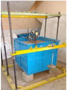
Loading Frame
The loading frame to apply static uplift loads and static lateral loads on piles is shown in Fig.2. The static uplift loads and static lateral loads were applied to the pile caps by means of dead weights placed on a loading hanger connected to a flexible steel rope, strung over a pulley supported by a loading frame. The loading frame had a provision to vary the heights of the pullies so as to apply the load either horizontally, vertically or in any inclined direction.
Test Procedure
Lateral Load Tests
The static lateral load tests were conducted on piles as per the procedure recommended by IS: 2911 (Part 4)–1985.The static lateral load was applied in increments by adding dead weights through the loading arrangement. For each increment of loading, the horizontal deflection of the pile head was measured at different times after loading with the help of dial guages. When the deflection of the pile head ceases, the next load increment was applied. The test was continued until the specified maximum deflection value of 5 mm was reached.
Uplift Load Tests
The static uplift load tests were conducted on piles as per the procedure recommended by IS: 2911 (Part 4)–1985 (BIS 1985). Before applying the load, the initial reading in the dial gauges was noted. The static uplift load was applied in several increments by adding dead weights through a loading arrangement. For each increment of loading, the pile head movement was measured at different times after loading. When the pile head movement ceases, the next load increment was applied. The test was continued until the failure of the pile takes place.
Tests Under Combined Loading
In first group of experiments, initially 20% of ultimate uplift load was applied to the pile / pile group. Then initial reading in the dial guages were made zero. Then static lateral load was applied in increments by adding dead weights through the loading arrangement. For each increment of loading, the horizontal deflection of the pile head was measured at different times after loading. When the deflection of the pile head ceases, the next load increment was applied. The test was continued until the specified maximum deflection value of 5 mm was reached. The same procedure was repeated for uplift load equal to 40% and 60% of the ultimate load.
In second group of experiments, initially 20% of ultimate lateral load was applied to the pile / pile group.Then initial reading in the dial guages were made zero. The static uplift load was applied in several increments by adding dead weights through a loading arrangement. For each increment of loading, the pile head movement was measured at different times after loading. When the pile head movement ceases, the next load increment was applied. The test was continued until the failure of the pile takes place. The same procedure was repeated for lateral load equal to 40% and 60% of the ultimate load.
Test Program
Laboratory studies were conducted on model pile / pile groups with differing number of model piles and lengths of pile. The pile / pile groups were subjected to uplift and lateral loading in the laboratory model loading setup and their ultimate capacities were determined. The details of parametric study is given in Table 2.
Table 2: Details of Parametric Study
Sr. No. Parameters Details of parameter 1 Number of piles
(N)& pattern
N = 1, 4 (Square pattern) & 6 (Hexagonal pattern) 2 Length to diameter
ratio (L/D) L/D = 10, 20, 30 & 40 3 Types of loading
i. Uplift ii. Lateral iii. Combined uplift and
IV. RESULTSANDDISCUSSION
Overall, 80 tests were conducted for single pile, square pile group and hexagonal pile group. The static lateral load tests were conducted on piles as per the procedure recommended by IS: 2911 (Part 4)–1985. Thetest was continued until the specified maximum deflection value of 5 mm was reached. The static uplift load tests were conducted on piles as per the procedure recommended by IS: 2911 (Part 4)–1985. This procedure was repeated until the failure of the pile takes place.
Behaviour of single Pile under Lateral Load
The ultimate lateral load capacities of single pile for different L/D ratio is shown in Fig.3. From figure it is seen that there is increase in lateral load capacity of pile with increasing the L/D ratio of pile. Lateral load capacity of single pile increases significantly with increase in L/D ratio up to 30, however beyond 30 increase in lateral capacity is marginal.
Figure 3: Variation of lateral load capacity of single pile with L/D ratio
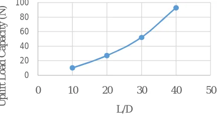
Behaviour of single Pileunder Uplift load
The ultimate uplift load capacities of single pile for different L/D ratio is shown in Fig.4. It is seen that there is significant increase in uplift load capacity of pile with increase in L/D ratio of pile.
Figure 4: Variation of uplift load capacity of single pile with L/D ratio
Behaviour of single Pile under combined loading
The variation of ultimate lateral capacity with pile length measured from tests for various uplift load is shown in Fig.5. It is seen that lateral load capacity of single pile increases significantly with increase in L/D ratio up to 30. However, beyond 30 increase in lateral capacity is marginal under constant uplift loads.
0 20 40 60 80
0 10 20 30 40 50
L
a
te
ra
l
L
o
a
d
C
a
p
a
ci
ty
(N
)
L/D
0 20 40 60 80 100
0 10 20 30 40 50
U
pl
if
t
L
o
a
d
Ca
pa
ci
ty
(N
)
Figure 5: Variation of ultimate lateral capacity of single pile with L/D ratio for various uplift load
The variation of ultimate uplift capacity with pile length measured from tests for various lateral load is shown in Fig.6. From figure, it is seen that uplift load capacity increases with increase in L/D ratio of pile under constant lateral loads.
Figure 6: Variation of ultimate uplift capacity of single pile with L/D ratio for various lateral load
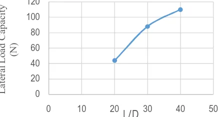
Behaviour Square Pile group under Lateral Load
The ultimate lateral load capacities of the pile for different L/D ratio is shown in Fig.7. From figure, it is seen that increase in lateral load capacity is high when L/D ratio increases from 20 to 30. However, as the L/D ratio is increased beyond 30, increase in lateral capacity is comparatively lower.
Figure 7: Variation of ultimate lateral load capacity of square pile group with L/D ratio
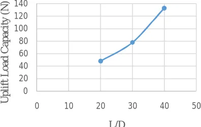
Behaviour of Square Pile group under Uplift Load
The ultimate uplift load capacities of the pile for different L/D ratio is shown in Fig.8. From figure, it is seen that increase in uplift load capacity is less when L/D ratio increases from 20 to 30. However, as the L/D ratio is increased beyond 30, increase in lateral capacity is high.
0 20 40 60 80 100
0 10 20 30 40 50
U lt im a te L a te ra l L o a d (N ) L/D
P = 0
P = 0.2 Pu
P = 0.4Pu
P = 0.6 Pu
0 20 40 60 80 100 120 140
0 20 40 60
U lt im a te U pl if t L o a d (N ) L/D
H = O
H = 0.2 Hu
H = 0.4 Hu
H = 0.6 Hu
0 20 40 60 80 100 120
0 10 20 30 40 50
Figure 8: Variation of ultimate uplift load capacity of square pile group with L/D ratio
Behaviour of Square Pile group under combined loading
The variation of ultimate lateral capacity with pile length measured from tests for various uplift load is shown in Fig.9. It is seen that lateral load capacity of square pile group increases significantly with increase in L/D ratio up to 30, however beyond 30 increase in lateral capacity is marginal under constant uplift loads.
Figure 9: Variation of lateral load capacity of square pile group with L/D ratio for various uplift load
The variation of ultimate uplift capacity with pile length measured from tests for various lateral load is shown in Fig.10.From figure, it is seen that increase in uplift load capacity is less when L/D ratio increases from 20 to 30. However, as the L/D ratio is increased beyond 30, increase in lateral capacity is high under constant lateral loads.
Figure 10: Variation of ultimate uplift load capacity of square pile group with L/D ratio for various lateral load 0 20 40 60 80 100 120 140
0 10 20 30 40 50
U pl if t L o a d Ca pa ci ty (N ) L/D 0 20 40 60 80 100 120 140
0 20 40 60
U lt im a te L a te ra l L o a d (N ) L/D
P = 0
P = 0.2 Pu
P = 0.4 Pu
P = 0.6 Pu
0 20 40 60 80 100 120 140 160
0 10 20 30 40 50
U lt im a te U pl if t L o a d (N ) L/D
Behaviour of Hexagonal Pile group under Lateral Load
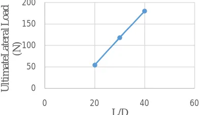
The ultimate lateral load capacities of the hexagonal pile group for different L/D ratio is shown in Fig.11.It is seen that lateral load capacity of hexagonal pile group increases almost linearly with increase in L/D ratio from 20 to 40.
Figure 11: Variation of ultimate lateral load capacity of hexagonal pile group for L/D ratio
Behaviourof Hexagonal Pile group under Uplift Load
The ultimate uplift load capacities of the hexagonal pile group for different L/D ratio is shown in Fig.12. It is seen that uplift load capacity of hexagonal pile group increases marginally up to L/D ratio 30 and increases significantly as L/D ratio changes beyond 30.
Figure 12: Variation of ultimate uplift load capacity of hexagonal pile group for L/D ratio
Behaviourof Hexagonal Pile group under combined loading
The variation of ultimate lateral load capacity with pile length measured from tests for various uplift load is shown in Fig.13. It is seen that lateral load capacity of hexagonal pile group increases almost linearly with increase in L/D ratio from 20 to 40 under constant uplift loads.
Figure 13: Variation of ultimate lateral load capacity of hexagonal pile group with L/D ratio for various uplift load 0
50 100 150 200
0 20 40 60
U
lt
im
a
te
L
a
te
ra
l L
o
a
d
(N
)
L/D
0 50 100 150 200 250 300
0 20 40 60
U
pl
if
t
L
o
a
d
(N
)
L/D
0 50 100 150 200
0 20 40 60
L
a
te
ra
l
L
o
a
d
(N
)
L/D
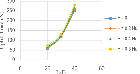
The variation of ultimate uplift capacity with pile length measured from tests for various lateral load is shown in Fig.14.It is seen that uplift load capacity of hexagonal pile group increases marginally up to L/D ratio 30 and increases significantly as L/D ratio increases beyond 30 under constant lateral load.
Figure 14: Variation of ultimate uplift load capacity of hexagonal pile group with L/D ratio for various lateral load
V. CONCLUSIONS
Based on the results obtained from the experimental investigation, the following conclusions are drawn
[1] Lateral load capacity of single pile increases significantly with increase in L/D ratio up to 30, however beyond 30 increase in lateral capacity is marginal for both; independent lateral loading and under combined loading with constant uplift load.
[2] Uplift load capacity of single pile increases linearly with increase in L/D ratio from 10 to 40 for both; independent uplift loading and under combined loading with constant lateral load.
[3] Lateral load capacity of square pile group increases substantially with increase in L/D ratio up to 30, and marginally increases for L/D ratio beyond 30 for independent lateral loading as well as under combined loading with constant uplift load.
[4] Uplift load capacity of square pile group increases with increase in L/D ratio from 20 to 40for independent uplift loading and also under combined loading with constant lateral load.
[5] Lateral load capacity of hexagonal pile group increases almost linearly with increase in L/D ratio from 20 to 40for independent lateral loading and under combined loading with constant uplift load.
[6] Uplift load capacity of hexagonal pile group increases marginally up to L/D ratio 30 and increases significantly as L/D ratio changes beyond 30 for independent uplift loading and under combined loading with constant lateral load.
[7] Lateral load capacity of single pile / pile group increases due to application of uplift load. Higher the magnitude of uplift load, higher will be the lateral load capacity.
[8] Uplift load capacity of single pile / pile group increases due to application of lateral load. Higher the magnitude of lateral load, higher will be the uplift load capacity.
REFERENCES
[1] Patra, N. R., and Pise, P.J., ‘‘Ultimate Lateral Resistance of Pile Groups in Sand’’,Journal of Geotechnical and Geoenvironmental Engineering, ASCE, Vol. 127 No.6, pp. 481–487, 2001.
[2] Chandrasekaran, S., Boominathan, A., and Dodagoudar, G. R., “Group Interaction Effects on Laterally Loaded Piles in Clay”, Journal of Geotechnical and Geoenvironmental Engineering, ASCE, Vol.136, No. 4, pp. 573-582, 2010.
[3] Sudharani, S., and Rakaraddi P., “An Experimental Study on Vertical Uplift Capacity of Piles”,Proceedings of IGC 2014, pp. 1996-2004, 2014.
[4] Shah, M., and Vaniya J., “Model Test to Determine Uplift Capacity & Settlement Characteristics of Mono Piles Embedded in Sandy Soil”,Proceedings of IGC 2014, pp.2146-2153, 2014.
[5] Reddy, K., and Ayothiraman R., “Experimental Studies on Behavior of Single Pile Under Combined Uplift and Lateral Loading”,Journal of Geotechnical and Geoenvironmental Engineering, ASCE, Vol.141, 2015.
[6] Chapparaband, N., and Rakaraddi P., “Experimental Study on Laterally Loaded Driven Single & Group of Pile”,Proceedings of IGC 2014, pp.2374-2382, 2014.
0 50 100 150 200 250 300
0 20 40 60
U
pl
if
t
L
o
a
d
(N
)
L/D
H = 0
H = 0.2 Hu
H = 0.4 Hu