A Study of Cooling of Continuously Variable
Transmission (CVT)
Mayur U Patil 1, Kaushik Bharadwaj1, Sameer Sathwick1, Baskar.P2 P.G. Student, SMEC, VIT University, Vellore, Tamilnadu, India1
Associate Professor, SMEC, VIT University, Vellore, Tamilnadu, India2
ABSTRACT: Continuously variable transmission (CVT) is an automatic transmission used to obtain infinite gear ratios between driver and driven shafts. They are used in scooters, Baja vehicles etc. Engine power is transmitted from driver side to driven side (secondary) by means of a belt and pulleys. Infinite gear ratios are obtained by varying belt diameter over pulleys. At higher speed instances and clutch slippage situations more heat is generated in CVT components and if it is operated for a long run it also affects the service life of components and simultaneously performance is reduced. So, cooling of CVT is necessary. This research aims at reducing the surface temperature around the pulleys of a CVT. Work consists of design modification of CVT and changing material of the pulleys to increase heat flow rate. The temperature distribution is analyzed for different designs using steady state thermal analysis tool in Ansys.
KEYWORDS: CVT, automatic transmission, gear ratio
I. INTRODUCTION
Transmission allows the variation of torque between engine crank and road wheels by using gearbox. Automobiles require different torque at various driving conditions. Transmission is mainly classified as manual transmission and automatic transmission. Manual transmission consists of changing gears manually by using a clutch and gearshift lever. So performance of transmission is dependent on skill of the driver. Whereas in automatic transmission gear change is done by sensing speed of the vehicle all automatically. There is no need of disengaging clutch and driver is free from gear changing efforts. Continuously variable transmission (CVT) is a step less automatic transmission which offers infinite number of gear ratios. A pulley based CVT is used for investigation in current work, which consists of two V belt pulleys which are split in between to accommodate the V belt. Primary pulley is connected to engine crank side and secondary pulley to wheel side. The gear ratio is changed by moving the two sheaves of one pulley closer together and the two sheaves of the other pulley farther apart, which changes effective diameter of both the pulleys. The contact between V belt sidewalls and pulley groove is the main source of heat generation in CVT. This temperature generation affects the service life of pulley and belt due to material degradation. Expansion of belt due to heating results in loss of transmission efficiency and less durability of CVT parts. Studies show that CVT temperature may reach up to 150 0C. Present paper deals with design modification and change in material of pulleys to achieve better heat dissipation properties. New material used is aluminium metal matrix composite (Al MMC) due to its high thermal conductivity and design modification involved provision of fins and holes.
II. RELATEDWORK
ISSN(Online) : 2319-8753 ISSN (Print) : 2347-6710
I
nternational
J
ournal of
I
nnovative
R
esearch in
S
cience,
E
ngineering and
T
echnology
(An ISO 3297: 2007 Certified Organization)
Vol. 5, Issue 11, November 2016
Vaishya A. et al. [2] studied air flow path and air flow rate inside CVT casing. Increase in air inlet and outlet area was 4 % and 22 % respectively. Corresponding changes were reduction in air inlet temperature by 15 0C and 13 % increase in air flow at outlet. Modifications reduced maximum belt temperature by 20 0C, also driver and driven pulley temperature reduced by 5 0C. Karthikeyan N. et al. [3] performed CFD analysis of CVT for air flow path modification to reduce clutch temperature. Change in fan design, provision of convergent guide and increasing outlet area by 184 % improved clutch housing flow by 40 % and clutch surface temperature reduced by 8 0C.
Belt is a crucial component in thermal characteristics of a CVT. The power is lost to bending, compression and shearing of the belt from friction, belt hysteresis, belt engagement and disengagement. Losses depends upon properties of the belt [4]. Design modification of belt is also a way to decrease heat generation. Lolli Sergio et al. [5] improved shape and material characteristics of belt to develop a new belt called as CVTH belt. It composed of a continuity element, polymeric rigid material and rubber stiffened by fiber cords. Good distribution of belt contact area and belt lifetime of 200 hours at 90 Nm torque was obtained. Johannes wurm et al. [6] developed a numerical model predicting thermal conditions of a CVT. A time efficient and novel model was developed to find temperature profile. The heat generated in CVT is dissipated through CVT fluid. Many researchers evaluated properties of these fluids for better heat dissipation. Murakami et al. [7] developed a new CVT fluid and evaluated its traction coefficient with respect to contact pressure, fluid temperature and slip ratio. The newly developed T-CVT fluid was superior to conventional fluids. Bert Pennings et al. [8] performed fluid test to find cooling and heat dissipation characteristics. Results were compared with a reference fluid and suitability of a specific fluid for a push belt CVT operation was obtained.
III.METHODOLOGY
A.BASE DESIGN
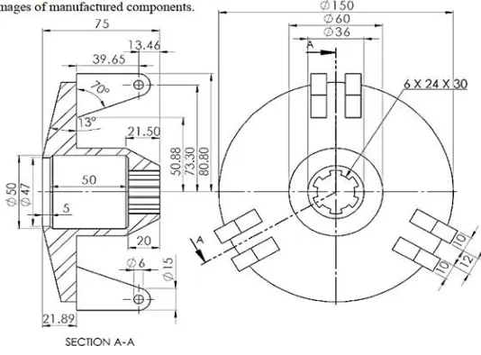
Pulley based CVT model is created in CATIA V5 from the drawings of B&S engine with a capacity of 10hp which is used in BAJA vehicle [9]. Figure 1 and Fig.2 shows the dimensions of movable and fixed pulley on primary clutch side respectively. Figure 3 shows dimensions of fixed and movable pulleys on secondary clutch.
Fig. 2.Dimensions of fixed pulley on the side of primary clutch Fig. 3. Dimensions of fixed and movable pulleys on secondary clutch
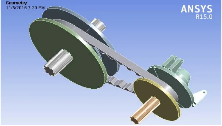
Three dimensional sketch of CVT drawn from given dimensions is showed in Fig.4. Belt used for this type of CVT is made of cogged version of steel. Specifications of belt are mentioned below
Belt length: 1022.54 mm
Belt dimensions: 18.66 mm x 10 mm Internal grove angle: 600
ISSN(Online) : 2319-8753 ISSN (Print) : 2347-6710
I
nternational
J
ournal of
I
nnovative
R
esearch in
S
cience,
E
ngineering and
T
echnology
(An ISO 3297: 2007 Certified Organization)
Vol. 5, Issue 11, November 2016
B. MODIFIED DESIGN
From Fourier’s law of heat conduction heat transfer through a body is given by,
Q = - k A (dT/dx) (1)
Where A is cross sectional area of heat transferring element k is thermal conductivity of the body and (dT/dx) is temperature gradient
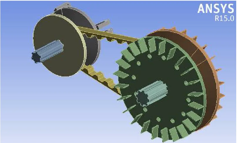
So, to achieve better heat dissipation one way is to increase heat transfer area A, which is done by using extended surfaces called fins. Hence, in our modified design secondary pulleys are incorporated with fins of cross section 30 mm x 2 mm of length 20 mm. Also holes of 10 mm diameter with depth 10 mm are introduced to compensate the weight increase in pulley due to attachment of fins. Due to which heat transfer area is increased by 27.41 %
Another factor in heat transfer is thermal conductivity (k) of material, which is the ability of a material to conduct heat. So, increasing thermal conductivity will also increase heat transfer. As thermal conductivity of aluminium (Al) metal matrix composite (MMC) is higher than steel and it also possesses low weight, low wear, high strength and low coefficient of thermal expansion, pulleys are assigned with Al MMC to improve the heat dissipation characteristics. Al MMC used is Al MMC T5 [10] which is A356 alloy with 20% SiC reinforcement and properties of it are shown in table 1.
Table 1.Properties of Aluminum MMC
Properties Value
Elastic modulus 108.2 Gpa
Ultimate tensile strength 320.6 Mpa
Thermal Conductivity 97 W/m-k
Specific heat capacity 0.798 J/g-0c
Mass density 2.75 g/cc
Poisson’s ratio 0.33
Coefficient of friction 0.37
Tensile strength at upper yield point 260 Mpa
Coefficient of thermal expansion 14 x 10-6/0 C
Fig. 5. Modified design of pulley based CVT
C. STEADY STATE THERMAL ANALYSIS
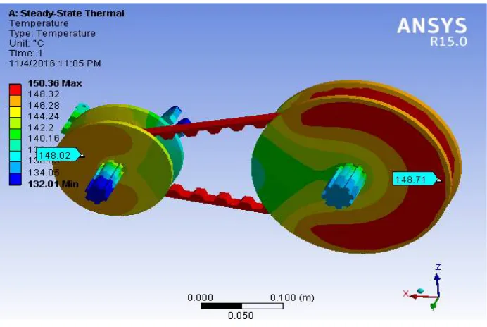
To find out the temperature distribution around the surface of pulleys of CVT steady state thermal analysis is used in ANSYS work bench. Thermal analysis is done by applying temperature of 150 0C [11] on belt surface where maximum heat is generated. Base model and modified design model are analyzed. Surface temperatures around the surface of pulley of both the models are compared. The boundary conditions are applied as given below
Initial temperature: 220 C
Temperature over the belt: 1500 C
Convection film coefficient between steel and air: 7.9 W/m2 0 C
Convection film coefficient between Al MMC and air [12]: 147 W/m2 0C
IV.RESULTS AND DISCUSSIONS
ISSN(Online) : 2319-8753 ISSN (Print) : 2347-6710
I
nternational
J
ournal of
I
nnovative
R
esearch in
S
cience,
E
ngineering and
T
echnology
(An ISO 3297: 2007 Certified Organization)
Vol. 5, Issue 11, November 2016
Fig. 6.Temperature distribution over the pulley surface for a base model design of CVT
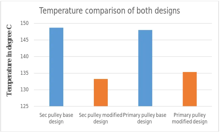
Thus from results it can be seen from graph of Fig. 8 that secondary pulley temperature is reduced by 15.47 0C and primary pulley temperature is reduced by 12.67 0C. So, using fins on secondary pulley and changing pulley material to Al MMC reduced secondary pulley and primary pulley temperature by 10.4 % and 8.55 % respectively
Fig. 8 Comparison of temperature for base design and modified design
V. CONCLUSION
Providing fins and changing material of CVT pulleys caused a drop in temperature of CVT system. It can be concluded that by adapting design modifications to pulley based CVT
1. Temperature on the surface of secondary pulley is reduced nearly by 10.40 % 2. Temperature on the surface of primary pulley is reduced nearly by 8.55 %
3. From results it can be seen that secondary pulley temperature is reduced by 15.47 0C and primary pulley temperature is reduced by 12.67 0C
4. Provision of fins increased heat transfer area by 27.41 %
5. The reduction in temperature is due to large heat transfer area of fins and higher thermal conductivity of Al MMC.
REFERENCES
[1] Dhongde, Snehal Vasant, and Vinilkumar Chandran,“Experimental Study of cooling of Continuously Variable Transmission (CVT) in
Scooter”, No. 2014-01-2003, SAE Technical Paper, 2014.
[2] Vaishya, Abhishek Lakhanlal, and Sachin Phadnis,“Experimental Investigations of Forced Air Cooling for Continuously Variable
Transmission (CVT)”, No. 2013-32-9073, SAE Technical Paper, 2013.
[3] Karthikeyan, N., Anish Gokhale, and Narendra Bansode, “A Study on Effect of Various Design Parameters on Cooling of Clutch for a
Continuously Variable Transmission (CVT) System of a Scooter”, No. 2014-01-2595, SAE Technical Paper, 2014.
[4] Bertini, L., L. Carmignani, and F. Frendo. "Analytical model for the power losses in rubber V-belt continuously variable transmission (CVT)",
Mechanism and Machine Theory 78 (2014): 289-306.
[5] Lolli, Sergio, et al, “A theoretical and experimental procedure for design optimization of CVT belts”, No. 2003-01-0973, SAE Technical
Paper, 2003. 125 130 135 140 145 150
Sec pulley base design
Sec pulley modified design
Primary pulley base design Primary pulley modified design T em p er a tu r e in d egr ee C
ISSN(Online) : 2319-8753 ISSN (Print) : 2347-6710
I
nternational
J
ournal of
I
nnovative
R
esearch in
S
cience,
E
ngineering and
T
echnology
(An ISO 3297: 2007 Certified Organization)
Vol. 5, Issue 11, November 2016
[6] Wurm, Johannes, et al. "Novel CFD approach for the thermal analysis of a continuous variable transmission (CVT)", Applied Thermal
Engineering 103 (2016): 159-169.
[7] Ishikawa, Takao, et al,“The effect of belt-drive CVT fluid on the friction coefficient between metal components”, No. 972921, SAE Technical
Paper, 1997.
[8] Pennings, Bert, et al. Van Doorne, “CVT Fluid Test: A Test Method on Belt-Pulley Level to Select Fluids for Push Belt CVT Applications”,
No. 2003-01-3253, SAE Technical Paper, 2003.
[9] Viren Gabani, “CVT brief report”, No. 261794530, researchgate publications 2016.
[10] Kero, Matt, and Andrew Halonen, “Development and Testing of Lightweight Aluminum Composite Brake for Medium to Heavy Duty
Vehicles”, No. 2010-01-1705, SAE Technical Paper, 2010.
[11] Crolla, David, ed.,“Automotive Engineering e-Mega Reference”, Butterworth-Heinemann, 2009.
[12] Xiao, Bowang, et al., "An experimental study of heat transfer during forced air convection", Journal of materials engineering and performance