Transactions of the 17th International Conference on Structural Mechanics in Reactor Technology (SMiRT 17)
Prague, Czech Republic, August 17 –22, 2003
Paper # K09-5
Development of Three -Dimensional Base Isolation System with Cable
Reinforcing Air Spring
Mitsuru Kageyama1), Tsutomu Iba2), Katsuhiko Umeki2), Takahiro Somaki2), Satoshi Moro3)
1)
Technical Research institute, Obayashi Corporation, Tokyo, Japan
2)
Engineering Department, Nuclear Facilities division, Tokyo, Japan
3)
The Japan Atomic Power Company, Tokyo, Japan
ABSTRACT
In Japan, studies on application of two-dimensional base isolation systems to FBR (Fast Breeder Reactor) or PWR (Pressurized Light Water Reactor) plants have been continuing for about 15 years. The technical guideline for the horizontal base isolated nuclear power plants was published in 2001. The aims at applying the base isolation system for nuclear power plants are to establish a site-free design standard for nuclear power plants, free from seismic design bindings, and to reduce the construction cost.
Since the two-dimensional isolation system (horizontal isolation) enables a considerable reduction on equipment/piping responses in the horizontal direction, compared with non-isolated conventional buildings, the thickness of structural walls besides the neutron shield can be reduced to achieve the reduction in construction cost. However the vertical responses of the equipment/piping in the horizontal base isolated buildings tend to be greater than in the non-isolated conventional buildings due to amplification in the isolation layer and in the superstructure. Therefore the reinforcement of vertical seismic supports for equipment/piping is required depending on the seismic conditions in site. The development of the three-dimensional isolation system is expected from the viewpoint of achieving further cost reduction in constructing nuclear power plants.
The superlative three-dimensional base isolation system for the entire building is proposed. The system is composed of cable reinforcing air springs, rocking prevention devices and dampers. The dimension of the air spring applying to the actual power plant is 8 meters in the outer-diameter and 3.5 meters in height. The allowable half strokes are respectively 1.0 meters for the horizontal direction and 0.5 meters for the vertical direction. The supporting weight for a single device is 52MN, where the inner air pressure is about 1.4MPa. This air spring enables to realize three-dimensional base isolation with a single device, whose natural periods are about 4 seconds in the horizontal direction and about 3 seconds in the vertical direction.
Furthermore, this air spring does not require precise mechanical parts but just common building materials, which are steel, cable wire, polyester fabric and a rubber sheet. Therefore, the manufacturing cost for this device could be on the inexpensive level.
In order to confirm the performance of this proposal system, experimental tests using the three dimensional shaking table were carried out. The test specimen is 1/4 scale of the actual size. The outer diameter and inner air pressure of air spring is 2 meters and 0.25MPa, respectively. So the supporting weight of sir spring is approximately 392KN including a 4-story steel frame.
As a result, the proposal system was confirmed to behave smoothly in three directions with natural periods of 1.8 seconds in horizontal direction and 1.4 seconds in vertical direction, which almost met the design value. And the behaviors of this system during the earthquake were simulated by the seismic response analyses. Therefore, it is greatly expected that the proposed system can be applied to actual nuclear power plants.
KEY WORDS: Three-dimensional seismic isolation system, Cable-reinforcing air spring, Shaking table test,
Simulation analysis, FBR, Applicability to actual NPP plants
INTRODUCTION
with existing two-dimensional base isolation systems. Furthermore, it is also expected to establish a site-free three-dimensional base isolation system design standard for nuclear power plants.
An idea with the concept of a cable reinforcing air spring was proposed as the three-dimensional base isolation device. The dimension of the air spring applying to the actual power plant is 8 meters in the outer-diameter and 3.5 meters in height. The allowable half strokes are 1.0meters in horizontal direction and 0.5 meters in vertical direction, respectively. The supporting weight for a single device is 52MN, where the inner air pressure is about 1.4MPa.
This device enables to realize three-dimensional base isolation with a single device, whose natural periods are about 4 seconds in horizontal and about 3 seconds in vertical. Furthermore, this device does not require precise mechanical parts but just common building materials, which are steel, cable wire, polyester fabric and a rubber sheet. So, the construction cost for this device could be on the inexpensive level.
OUTLINE OF THE THREE–DIMENSIONAL BASE ISOLATION SYSTEM
1) Design concept
As shown in Fig.1, the proposed base isolation concept is a three-dimensional air spring to support and isolate the superstructure by compressed air, which is composed of a rubber sheet between the inner and outer cylinders, reinforcing polyester fabric, and wire cables. Herein, the inner cylinder is set on the bottom base-mat and the outer cylinder is connected to the upper base-mat.
The distance between the inner and outer cylinders is the allowable stroke for the device to move in the horizontal direction, and the distance between the top of the inner cylinder and the upper structure is the allowable stroke for the device to move in the vertical direction. Since the movement in 3 dimensions is possible, three-dimensional base isolation is realized with a single device.
The shape of the inner cylinder connected to the rubber sheet is designed so that the total circumference of the inner and outer cylinders are the same to avoid wrinkles of the rubber sheet at the inner cylinder when the rubber sheet scrolls down. This allows the smooth movement of the device, in both horizontal and vertical directions.
2) Outline of the actual device
The three-dimensional base isolation system applying to an actual nuclear power plant was planned and designed. The allowable horizontal half stroke and vertical half stroke of this air spring are respectively 1.0 meters and 0.5meters. The supporting design load is 52 MN, therefore a total of 32 devices support the entire power plant weight of 1,666MN. Under this condition the inner pressure is approximately 1.4MPa.
The target vertical frequency ‘fv’ was less than 1.0Hz and the vertical damping factor ‘hv’ was from 20% to 40% by Kato et al (1). The developed three-dimensional base isolation system for an actual plant has the characteristics of fh=0.27Hz, fv=0.35Hz, and h=20% in both horizontal and vertical directions for higher performance.
a) Size and layout of the base isolation device
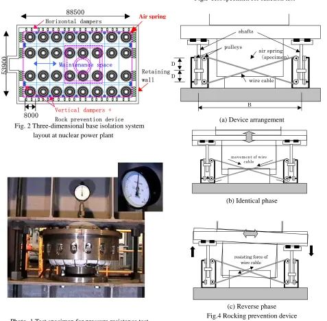
The layout of the devices for a nuclear power plant is shown in Fig. 2. The overall specifications of the air spring are as follows;
i. diameter of outer cylinder: 8.0meters ii. diameter of inner cylinder: 6.0meters
iii. allowable horizontal displacement: 1.0meter iv. height of inner cylinder: 3.0meters
v. allowable vertical displacement: 0.5meters vi. standard inner pressure: 1.4MPa
vii. main wire cable size and layout interval: 45mm,@500mm viii. secondary wire cable size and layout interval:14mm,@100mm ix. thickness of rubber sheet: 3mm at general portion, 4mm at end portion b) Supplementary equipment
Together with the main air springs, supplementary equipment listed hereunder is used; i. rocking prevention device
iii. vertical damper (20% damping):5MN oil damper, 22 units iv. air pressure controlling system
- air leak detector
- air supply for small leaks
- air supply for the 32 air springs required for initial air pressure
TEST AND SIMULATION ANALYSIS
1) Objective
As the first step to confirm the capabilities of the three-dimensional base isolation system, pressure resistance test and function tests were carried out. The following items were studied through the tests to confirm the integrity of the three-dimensional base isolation system.
a) Confirmation of pressure resistance and the structural integrity of the wire cable reinforcing system. b) To confirm the smooth movement of the device in 3-directions.
c) To confirm the three-dimensional base isolation performance of the function test specimen according to the theoretical evaluation.
2) Specimen for the pressure resistance test
A specimen with 0.3 meters in the outer diameter, which is scale model of 1/30 for the actual device, was designed and built to confirm the pressure resistance and the structural integrity (see Photo. 1).
3) Results of the pressure resistance test
From the pressure resistance test using water, the air tightness and structural integrity of the air spring composed of a rubber sheet, reinforcing textile and wire cables were confirmed. The rubber sheet is sealed by simple mechanism at the sides of the inner and outer cylinders.
The following results were obtained from the test;
a) Pressure resistance of the device up to 2.04MPa was confirmed.
b) Leak occurred from the rubber seal at the inner and outer cylinders. If sealing at a flat face with the use of bolts, more pressure resistance ability is expected.
c) From the dismantled specimen, it was found that the rubber sheet had a compression damage. So, the rubber sheet should be designed to form a tension structure so that it does not directly contact the inner and outer cylinders.
4) Specimen for the function test
Considering the results of the pressure resistance test, the function tests were conducted to confirm the three-dimensional movement of the device and its base isolating performance. The entire device is composed of 4 parts, the air spring, rocking prevention device, dampers and the weight, as shown in Fig.3. The scale of the air spring is 1/4 of the actual size, where the outer diameter and the height are 2 meters and 1.5 meters respectively. The inner pressure within the air spring is 0.25MPa and the gauge pressure is 0.15MPa, supporting the weight of 0.4MN.
As the air spring itself does not have any restoring force characteristics for the rocking, 4 sets of wire cable rocking prevention devices are combined, which surround the air spring in 2 horizontal directions.
This prevention device consists of 4 pulleys, 2 wire cables and shafts to which the wire cables are attached. The shafts are installed on the fixed apparatus through the slider in the vertical direction. This device operates as follows (see Fig.4). Regarding the vertical displacement by the vertical motion, when 2 shafts move in the same direction the 2 wire cables smoothly move without causing the tensile/compression force. If the air spring rocks and rotates by the horizontal motion, one shaft moves down and other one moves up. Since the one side of crossing wire cables becomes under tension and the movements of the 2 shafts is restricted by the tensile force of the wire cable, it is possible to prevent from rocking. Herein, on the top of the rocking prevention device connecting to the weight, sliders in 2 directions are set so that the smoothly horizontal movement is available.
5) Test procedures of the function test
The function tests were conducted on a three-dimensional shaking (see Photo. 2). The contents of the function tests are as follows;
a) Measuring the natural period of the device by evaluating the resonance curve obtained from sinusoidal excitation in the horizontal and vertical directions.
b) Input of seismic waves (horizontal, vertical, horizontal and vertical combined) to confirm the smooth movement of the device and the three-dimensional isolation performance, it’s seismic isolation performance and the effects of simultaneously input waves. The time axis of the waves was reduced to half the actual one according to the similarity rule. The following waves were used;
i. FBR case study wave (horizontal axis:Max 8.30m/s2) ii. FBR case study wave (vertical axis:Max 5.56m/s2)
iii. FBR case study wave (horizontal and vertical combined axis)
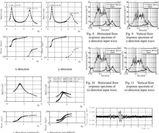
6) Resonance curves
Sinusoidal excitation was conducted on the function test specimen in 2 horizontal directions and the vertical direction. Fig.5 shows the resonance curves and phase angles in each X, Y and Z directions obtained from the tests. Here, the amplitude shows the ratio of the acceleration at the top of the frame to that right above the shaking table. From the results, the natural period of the device in the horizontal directions (X, Y) were found to be 1.79 seconds (0.56Hz) and the damping 16–17%. As for the vertical (Z) direction, a lag is recognized between the frequency at the primary peak of the resonance curve (original) and that of the phase angle at 90 degrees. This is considered to be due to the resonance with the shaking tables having natural period very close to 0.8Hz. Therefore the resonance curve was modified by evaluating the phase angle with relative velocity at the point right above the device (Z1) and above the shaking table (Z2). As the result, the vertical natural period of 1.35 seconds (0.74Hz) was calculated. In this way the natural period of the device in the vertical direction was judged to be 1.35 seconds (0.74Hz) and the damping 26.54%. Herein, the secondary peeks in the X and Y directions are due to the frame.
7) Floor response spectrum
The input motions of FBR case study waves at the point right above the shaking table are shown in Fig.6 and 7. Comparisons between the floor response spectrum at the point right above the device and horizontal, vertical and combined waves are shown in Fig.8-11. From these results, the seismic isolation performance of the device in the horizontal and vertical directions can be confirmed. As there is not much difference between the floor response spectrum of the horizontal wave (Fig.8) and the combination wave (Fig.10), it can be judged that the influence of the vertical movements on the horizontal response can be ignored.
8) Fluctuation of inner air pressure
The fluctuation of air pressure within the test specimen air spring during the horizontal case study wave is shown in Fig.12. The fluctuation of measured inner air pressure is at most about 1.5%. Therefore it is thought that the fluctuation of air pressure is almost none.
The fluctuation of air pressure within the test specimen air spring during the FBR vertical case study wave and the combined case study wave are shown in Fig.13 and 14, respectively. In these cases, the fluctuations of measured inner air pressures are 10% at most. Considering together with the floor response spectrum mentioned above, the influence of the vertical movement on the horizontal response is thought to be very small.
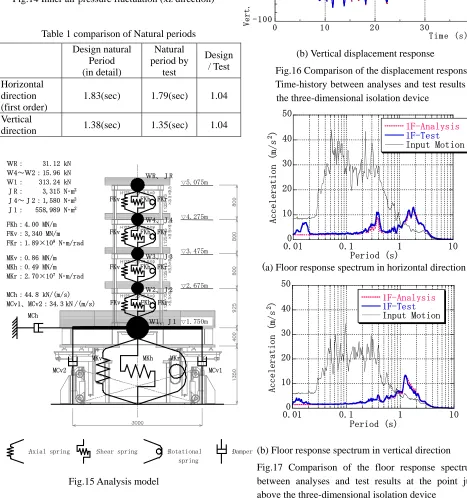
9) Comparison of test results with the design values
The comparison of natural periods between the test results and the design values are shown in Table 1. The design natural period of the device was evaluated in detail by considering the inclination of the wire cable (horizontal direction) and by assuming adiabatic change (vertical direction) of the air spring. (Tokita et al, 1992(2))
From this table, it is thought that the function test results were confirmed to be almost same as the design value (the theoretical evaluation).
Simulation analyses were carried out by the seismic response analyses. The analysis model and the detail of the characteristics used in the simulation analyses are shown in Fig.15.
As for the horizontal and vertical response displacements of the three-dimensional isolation device during the FBR case study waves, Fig.16 shows the comparison of the time history between the analyses and test results. The analyses simulate the response displacement of the test results very well.
Regarding the horizontal and vertical floor response spectrum at the point just above the three-dimensional isolation device, Fig.17 shows the comparison between the analyses and the test results. The analyses also simulate the floor responses of the test results very well.
It was confirmed that the response of this three-dimensional air spring during earthquakes could be simulated with high accurate by the method of seismic response analysis.
CONCLUSION
The superlative three-dimensional cable reinforced base isolation system to support an entire nuclear power plant was developed, which is composed of air springs, rocking prevention devices and dampers that are effective in both horizontal and vertical directions.
From the results of the enforced pressure resistance test and function tests, the pressure resistance performance of approximately 2MPa and the seismic isolation functions in 3 directions were confirmed.
The performance of the developed system can be evaluated by the theoretical method and can be simulated the actual behavior could be estimated by the seismic response analysis.
Accordingly, it is concluded that the developed system is feasible for applying to actual nuclear power plants.
ACKNOWREDGEMENTS
This study was made as a part of a government sponsored R&D project on three-dimensional seismic isolation. Special appreciation is given to Mr. Wataru Ota of The Yokohama Rubber Co., Ltd, Mr. Hideki Tagawa of Shinko Wire Co., Ltd, and Mr. Akimoto Uchikawa of Teijin Limited for their invaluable technical support to this study.
REFERENCES
(1) Kato, A., Umeki, K., Morishita, M., Fujita, T., Midorikawa, S.: A large Scale Ongoing R&D Project on Three-Dimensional Seismic Isolation for FBR in Japan, ASME PVP, Aug, 2002
Fig.1 Cable reinforcing three-dimensional air spring concept
Fig. 2 Three-dimensional base isolation system layout at nuclear power plant
Photo. 1 Test specimen for pressure resistance test
Fig.3 Test specimen for function test
(a) Device arrangement
(b) Identical phase
(c) Reverse phase Fig.4 Rocking prevention device
0.5m
3.0m
9.0m:outer cylinder
6.0m:inner cylinder
Horizontal dampers
Vertical dampers +
Rock prevention device
Maintenance space
88500
53900
8000
Retaining wall
Air spring
resisting force of wire cable
movement of wire cable
B
D
D
pulleys
wire cable air spring
(specimen)
shafts
Weight
Specime n
Damper
Shaking Table
2,000
Cable Wire for Rocking Prevention 2 dimensions slider
Photo. 2 Test specimen on 3D shaking table
x-direction y-direction - 1 0
- 5 0 5 1 0
0 1 0 2 0 3 0 4 0
Acce le r ation (m / s 2 )
T i m e ( s )
Fig.6 FBR horizontal case study wave
- 8 - 4 0 4 8
0 1 0 2 0 3 0 4 0
A cc elera ti o n( m/s 2 )
T i m e ( s )
- 0 . 0 0 4 - 0 . 0 0 2 0 0 . 0 0 2 0 . 0 0 4
0 5 1 0 1 5 2 0 2 5 3 0 3 5 4 0
Pr
essu
re rang
e (MPa
)
T i m e ( s ) 0 . 1 5 7
0 1 2 3 4 5
0 1 2 3 4 5
0.56Hz,h=16.9% 3.4Hz,h=8.3% Am pl it ude Hz 0 1 2 3 4 5
0 1 2 3 4
Hz Ampl it ud e 0.56Hz,h=16.0% 2.65Hz,h=5.1% -180 0 180
0 1 2 3 4 5
Phase Ang le Hz -180 0 180
0 1 2 3 4
Phas
e An
gle
Hz
Fig.7 FBR vertical case study wave
0 10 20 30 40 50
0.01 0.1 1 10
above device Input Ac ce le r ati on (m /s 2) Period(s)
0.1 1 5(Actual
0 10 20 30 40 50
0.01 0.1 1 10
above device Input A cce le r ati on (m /s 2) Period(s)
0.1 1 5(Actual t
Fig. 8 Horizontal floor response spectrum of x-direction input wave
Fig. 9 Vertical floor response spectrum of z-direction input wave
0 10 20 30 40 50
0.01 0.1 1 10
above device Input Ac ce le ra ti on (m /s 2) Period(s)
0.1 1 5(Actua
0 10 20 30 40 50
0.01 0.1 1 10
above device Input Ac ce le ra ti on (m /s 2) Period(s)
0.1 1 5(Actual tim
Fig. 10 Horizontal floor response spectrum of xz-direction input wave.
Fig. 11 Vertical floor response spectrum of xz-direction input wave.
0 1 2 3
0 1 2
Hz Am pli tu d e 0 1 2 3 4 5
0 1 2
absolute amplitude:(z1+z2)/z2
relative amplitude:z1/z2
Amp
lit
ude
Hz
z-direction (original) z-direction (modified) 0
180
0 1 2
Hz Ph a se A ngle 0 180
0 1 2
Pha
se Angle Hz
Fig.15 Analysis model
(b) Vertical displacement response
Fig.16 Comparison of the displacement response Time-history between analyses and test results for
the three-dimensional isolation device
- 0 . 0 2 - 0 . 0 1 0 0 . 0 1 0 . 0 2
0 5 1 0 1 5 2 0 2 5 3 0 3 5 4 0
Pressure
range
(MPa
)
T i m e ( s ) 0 . 1 5 7
- 0 . 0 2 - 0 . 0 1 0 0 . 0 1 0 . 0 2
0 5 1 0 1 5 2 0 2 5 3 0 3 5 4 0
Pressu
re rang
e (MPa
)
T i m e ( s ) 0 . 1 5 7
Fig. 13 Inner air pressure fluctuation (z direction)
Fig.14 Inner air pressure fluctuation (xz direction)
Design natural
Period (in detail) Natural period by test Design / Test Horizontal direction (first order)
1.83(sec) 1.79(sec) 1.04
Vertical
direction 1.38(sec) 1.35(sec) 1.04
Table 1 comparison of Natural periods
-200 0 2 00
0 1 0 2 0 30 4 0
Analysis Test Hori. D is pl acemnet (m m ) Time (s) -100 0 100
0 10 20 30 40
Analysis Test Ve rt. D is pl ac em net ( mm) Time (s) (a) Horizontal displacement response
0 10 20 30 40 50
0.01 0.1 1 10
1F-Analysis 1F-Test Input Motion Accele ra t io n (m /s 2 ) Period (s)
:Axial spring :Shear spring :Rotational :Damper
spring ▽5.075m ▽4.275m ▽3.475m ▽2.675m ▽1.750m WR、JR W4、J4 W3、J3 W2、J2 W1、J1 FKv FKh FKr
FKv FKh FKr
FKv FKh FKr
FKv FKh FKr
MCh
MKv MKh MKr
MCv2 MCv1 WR: 31.12 kN
W4~W2:15.96 kN W1: 313.24 kN JR: 3,315 N・m2 J4~J2:1,580 N・m2 J1: 558,989 N・m2
FKh:4.00 MN/m FKv:3,340 MN/m FKr:1.89×10⁹ N・m/rad
MKv:0.86 MN/m MKh:0.49 MN/m MKr:2.70×10⁷ N・m/rad
MCh:44.8 kN/(m/s) MCv1、MCv2:34.3 kN /(m/s)
0 10 20 30 40 50
0.01 0.1 1 10
1F-Analysis 1F-Test Input Motion Acc ele r at io n ( m/s 2 ) Period (s)
(a) Floor response spectrum in horizontal direction
(b) Floor response spectrum in vertical direction