EFFECTS OF ISFSI PAD FLEXIBILITY ON SOIL STRUCTURE (SSI)
ANALYSIS
Nicholas Callahan1, Charles Papadelis2, Paul Wilson3, George G. Thomas3, Mrinal Bose4
1
Associate Engineer, Stevenson & Associates, Cleveland, Ohio
2
Staff Engineer II, Stevenson & Associates, Cleveland, Ohio
3
Senior Consulting Engineer, Stevenson & Associates, Cleveland, Ohio
4
Senior Staff Engineer, Exelon Corporation, Chicago, Illinois
ABSTRACT
In performing a seismic structural qualification of the Independent Spent Fuel Storage Installation (ISFSI) pads at nuclear power plants, an integral step to this analysis is conducting the Soil-Structure Interaction (SSI) analysis to determine how the responses of the storage casks are affected by the properties of the underlying soil sub-grade and ISFSI pad itself. This paper investigates the conclusions reached by Bjorkman et al. (2001) using real-world examples from two separate ISFSI pad sites; one being a shallow soil site and the other being a rock site founded directly on top of the limestone sub-grade. The purpose of this paper is to demonstrate, using the real-world sample sites, how large a role pad flexibility and the composition of sub-grade play in the response of the spent fuel casks when performing the SSI analysis. It is concluded in Bjorkman et al. (2001) that pad flexibility is the most important and therefore a necessary parameter to consider when conducting SSI analyses.
To effectively explore these conclusions, a set of finite element models were developed for the SSI analysis using the software package SuperSASSI/PC. In addition a modal analysis using a finite element analysis software package (ANSYS) was performed. The resulting cask center of gravity (C.G.) peak directional acceleration values and critical mode frequencies and shapes are used to confirm the conclusions arrived upon in Bjorkman et al. (2001) that pad flexibility must be considered when performing seismic structural qualification analyses on ISFSI pads.
INTRODUCTION
There are several important steps in performing a seismic structural qualification of ISFSI pads at nuclear power plants. One of the most important steps in these analyses is the SSI analysis, which is used to determine how the properties of the given structure interact with the properties of the underlying soil sub-grade to obtain the resulting response of the structure during a seismic event. Because the SSI analysis is an integral step in the ISFSI pad analysis, it is important that these analyses be performed as accurately as possible. As reported by Bjorkman et al. (2001), there are many factors that influence the SSI analysis that must be properly accounted for; these factors include, but are not limited to, pad flexibility, composition of soil sub-grade, cask arrangement on the pad, and the shape and intensity of the ground response spectrum. Bjorkman et al. (2001) investigates three of these factors; pad flexibility, soil sub-grade composition, and cask arrangement on the pad. The final conclusion of this investigation was that pad flexibility is the most important parameter and therefore the most necessary factor needing investigation.
this paper; a shallow soil site that consists of approximately 45’ of compacted sand and glacial till underlying the ISFSI pad and 3’ thick layer of structural fill and a rock site consisting of limestone directly underlying the ISFSI pad and associated 3’ thick structural fill layer. The selection of these two separate sites is not for directly comparing the effect of the soil sub-grade on the ISFSI pads, but rather to investigate how the composition of the soil sub-grade affects the flexibility of the pad and the resulting cask C.G. peak directional accelerations and the pad mode shapes and frequencies.
Pad Flexibility
The primary focus of this paper is to investigate the conclusion developed in Bjorkman et al. (2001) with regards to pad flexibility using real-world examples. The method of modeling pad flexibility used in this investigation is slightly different than the method used previously. Bjorkman et al. (2001) increased the thickness of the ISFSI pad to investigate pad rigidity. The pad in this investigation is set at 2’ thick (the actual pad thickness at both locations). To simulate the rigid pad for the comparison, the elastic modulus of the ISFSI pad concrete is increased from the 5.03x10⁸ psf (calculated using a concrete compression strength (fc`) equal to 3,750 psi) for the flexible pad, to a value of 5.03x10
10
psf, an increase by a factor of 100. Additionally, normal weight concrete with density of 150 pcf and Poisson’s ratio of 0.2 are selected for these ISFSI pads, these values remain constant.
Pad Dimensions and Cask Configurations
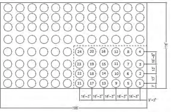
The pad dimensions and cask configurations on the pad remain constant throughout this analysis. The pad dimensions and cask configurations are the existing pad dimensions and configurations for the as-built pads as they exist today. The full pad dimensions are given as 198’-long by 116’-wide by 2’-thick reinforced concrete slab, which has a maximum loaded capacity of 96 spent fuel casks. The cask spacing configuration is shown in Figure 1 with the quarter pad section model used in the SSI analysis, the modal analysis model is taken as this quarter section mirrored about the vertical planes through the two orthogonal horizontal axes through the middle of the pad. The casks are identified by number for reporting the results. It is noted this is a typical spacing configuration for the casks. They are spaced close enough together to maximize capacity while not prohibiting the ability of the cask transport vehicle to place the casks in the appropriate arrangement.
Soil Sub-Grade Profiles
The sub-grade soil profiles also remain constant for the two soil sites. The shallow soil site is composed of the 2’-thick ISFSI pad, underlain by a 3’-thick layer of structural fill (density of 142 pcf, shear wave velocities varying from 976 fps to 1080 fps as the depth of the soil layer increases, elastic modulus of 1.413x10⁷ psf, and Poisson’s ratio of 0.25). The structural fill layer is underlain by a 15.5’-thick layer of vibro-compacted sand (density of 122 pcf, shear wave velocities varying from 541 fps to 594 fps as the depth of the soil layer increases, elastic modulus of 3.86x10⁶ psf, and Poisson’s ratio of 0.41), underlain by another 10’-thick layer of vibro-compacted sand (density of 128 pcf, shear wave velocities varying from 1170 fps to 1190 fps as the depth of the soil layer increases, elastic modulus of 1.54x10⁷ psf, and Poisson’s ratio of 0.41). The final layer of the sub-grade encountered before the bedrock half-space is an 18.5’-thick layer of glacial till (density of 144 pcf, shear wave velocities varying from 2280 fps to 2310 fps as the depth of the soil layer increases, elastic modulus of 6.28x10⁷ psf, and Poisson’s ratio of 0.38).
The rock soil profile is composed of the 2’-thick ISFSI pad underlain by a 3’-thick layer of structural fill (density of 136 pcf, shear wave velocity of 1100 fps, elastic modulus of 1.41x10⁷ psf, and Poisson’s ratio of 0.25). Additionally the first 15’ of the limestone half-space for the rock site is modeled (density of 161 pcf, shear wave velocities varying from 2880 fps to 2900 fps as the depth of the soil layer increases, elastic modulus of 1.166x10⁸ psf, and Poisson’s ratio of 0.39). The remainder of the limestone is treated as the bedrock half-space for the site.
Input Ground Motion
Input time histories are a necessary part of the SSI analysis. A separate set of three orthogonal time histories were developed for both sites, two horizontal and one vertical. Each of these time histories are developed independently in accordance with NUREG-0800, Section 3.7.1, Option 1, Approach II. This approach develops a set of synthetic time histories that either match or envelope the site-specific design response spectra. The design response spectra for the rock site was defined following the guidelines set forth in Regulatory Guide 1.60 for a horizontal peak ground acceleration scaled to 0.21g with 5% damping. The shallow soil site also followed the guidelines set forth in Regulatory Guide 1.60, but required a horizontal peak ground acceleration value scaled to 0.26g with 5% damping.
METHODOLOGY
The analysis performed consists of two main components; the first component is the SSI analysis, which is used to obtain the peak acceleration values at the C.G. of each cask on the pad. The acceleration values are obtained for all three orthogonal directions (two horizontals, X- and Y-Direction, and one vertical, Z-Direction). These acceleration values are compared for the flexible pad and rigid pad conditions to determine whether the rigid pad exhibits potentially un-conservative results. The second component of analysis is the modal analysis performed using a finite element analysis software package. The goal of the modal analysis is to illustrate whether a flexible pad is more active when exposed to a base excitation, and whether the flexible pad results in higher C.G. accelerations. To attain this goal, the critical mode frequencies and corresponding mode shapes are investigated.
computer program was employed to perform the SSI analysis and ANSYS was employed to perform the modal analysis. It is noted that SuperSASSI and ANSYS have been accepted for use in these nuclear safety-related applications by the NRC. In total, there are twelve SuperSASSI models run, three separate orthogonal direction runs for each of the rock site with flexible pad, the rock site with a rigid pad, the shallow soil site with a flexible pad, and the shallow soil site with the rigid pad. There are a total of four ANSYS models run, one modal analysis run each for the rock site with a flexible pad, the rock site with a rigid pad, the shallow soil site with a flexible pad, and the shallow soil site with the rigid pad.
Finite Element Modeling
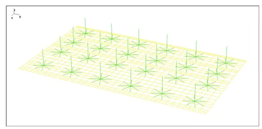
Both the SuperSASSI/PC and ANSYS programs employ the use of finite elements when modeling the structure. The model developed is nearly identical for both SuperSASSI and ANSYS, with the only difference being that the ANSYS model is taken as the quarter-pad mirrored about the vertical planes through the two orthogonal horizontal axes through the center of the pad. The quarter model for SSI analysis simulates the response of the entire 198’ X 116’ ISFSI pad loaded with 96 spent fuel casks, the quarter model is selected to provide for more efficient analysis run times while providing nearly identical results as a fully-modeled pad. Symmetrical and anti-symmetrical boundaries are employed in SuperSASSI to provide this quicker analysis while retaining the same level of accuracy of a fully modeled pad. The quarter-modeled pad result is a 99’ X 58’ ISFSI pad loaded with 24 spent fuel casks with symmetry boundaries. In addition to the pad size being reduced to support a smaller model, the modeling of the spent fuel casks is also simplified. The simplified cask models are taken directly from Bjorkman et al. (2001), which employs the use of mass-less beam, mass-less truss, and concentrated mass elements to simulate all essential components of the spent fuel casks (e.g. full cask mass, moments of inertia, the cask footprint, and the location of the C.G.) without the bulk of modeling the entire casks using solid elements. An illustration of the reduced cask model is shown in Figure 2.
Figure 2: Spent fuel cask reduced finite element model.
Figure 3: ISFSI quarter-pad modeled to simulate a fully loaded pad for SuperSASSI analysis.
Treatment of Soil Sub-Grade
Since both SuperSASSI/PC and ANSYS use finite elements when creating the model, the model defined above is used in both programs, with the only difference being how the soil sub-grade is modeled. The soil layers are explicitly modeled in SuperSASSI using a maximum soil layer thickness of 3.5’ (which corresponds to a cut-off frequency of 42.3 Hz, which is above the minimum acceptable cut-off frequency of 33 Hz). Additionally, the input properties required by SuperSASSI are the layer number, soil density, compression and shear wave velocities, and the compression and shear wave damping ratios.
ANSYS, however, does not provide an equivalent method of defining the soil sub-grade, so instead of defining the soil layers as in SuperSASSI, equivalent soil springs are modeled in ANSYS to simulate the behavior of the soil sub-grade. The soil spring stiffness values used are as follows: the shallow soil site employed 571,069 lb./ft. springs for the X-direction, 535,849 lb./ft. springs for the Y-direction, and 2,188,428 lb./ft. springs for the Z-direction; the rock site employed 5,086,792 lb./ft. springs for the X-direction, 4,955,975 lb./ft. springs for the Y-direction, and 11,064,151 lb./ft. springs for the Z-direction. The spring stiffness values are obtained from the global impedance function capability of the SSI analysis. These equivalent soil springs also provide the boundary conditions for the model, as each node on the bottom face of the ISFSI pad has a coincident node that is restrained in all directions. These springs are essentially equivalent to creating the soil sub-grade as in SuperSASSI.
RESULTS & OBSERVATIONS
In order to effectively accomplish the goal of validating the conclusions arrived at in Bjorkman et al. (2001), the following results are obtained from the analyses:
1. The maximum C.G. peak directional acceleration value and location of the corresponding cask for each of the three orthogonal directions for the four different soil site-pad flexibility combinations. The results are obtained from the SuperSASSI analysis and are reported in Table 1. 2. The number of critical mode frequencies reported for each of the four soil site-pad flexibility
combinations. Only frequencies between approximately 2 Hz and 33 Hz are of concern. These results are obtained from the ANSYS modal analysis and are tabulated in Table 1.
Table 1: Summary of critical mode frequencies and peak cask C.G. accelerations.
There is a significant difference in the peak C.G. acceleration values reported in Table 1 for the flexible pad versus the rigid pad, as predicted. The flexible pad model reports higher acceleration values than the rigid pad model in all three orthogonal directions of all four soil site-pad flexibility combinations. The maximum percent difference in peak acceleration values reported for the flexible pad versus the rigid pad is in excess of 56% greater, which is calculated from the X-Direction for the rock site. It is noted that there are some instances (rock site X-Direction, Y-Direction, and shallow soil site Z-Direction) that report different casks yielding the maximum peak acceleration value for a given direction. While this does not affect the method of analysis in any way, it is an interesting item to note that the pad flexibility affects more than just the C.G. acceleration values investigated herein.
The number of critical mode frequencies from the ANSYS modal analysis indicates the expected significant results differences between the flexible pad and rigid pad models. The flexible pad models at both soil sites return at least double the number of critical mode frequencies. This validates the conclusion from Bjorkman et al. (2001) that the flexible pads are more excitable within the frequency range of concern, which ultimately yields greater C.G. acceleration values.
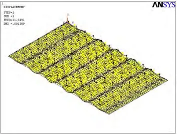
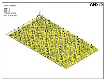
Figure 4: First mode shape for the rock site with flexible pad assumption.
Value (g) Cask ID1 Value (g) Cask ID1 Value (g) Cask ID1
Flexible Pad 0.4698 22 0.4322 24 0.2464 11 220
Rigid Pad 0.3006 21 0.3077 1 0.2445 11 98
Flexible Pad 0.4336 24 0.4881 24 0.3738 10 258
Rigid Pad 0.3923 24 0.4105 24 0.3649 1 98
1
Refer to Figure 1 for the cask ID number, used to show the location of the cask with largest peak acceleration value.
Number of Critical Mode Frequencies
(~2 Hz - 33 Hz)
Shallow Soil Rock
Pad Fle xibility Soil Site
Peak C.G. Acceleration in Z-Direction Peak C.G. Acceleration
in Y-Dire ction Peak C.G. Acceleration
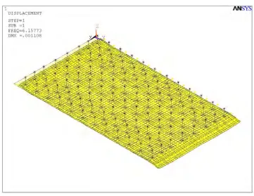
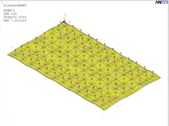
Figure 5: First mode shape for the rock site with rigid pad assumption.
Figure 7: First mode shape for shallow soil site with rigid pad assumption.
The mode shapes reported in the ANSYS modal analysis indicate that the added mass of the casks (which are considered individually as seismically rigid) induces a dynamic response in the form of the out-of-plane flexing of the pad. It is observed that for the flexible pad condition, the response of the pad and casks is aligned with the amplified region of the input ground motion, which promotes more localized flexing of the pad due to the casks, as shown in Figure 4 and Figure 6. The rigid pad condition, however, does not include this local flexing of the pad due to the initial response, which results in the more uniform flexing action by the pad observed in Figure 5 and Figure 7. The rigid pad condition does exhibit more localized out-of-plane flexing as it approaches the upper frequency range bound of 33 Hz, as is shown in Figure 8 and Figure 9. However, the frequencies at which this occurs are sufficiently high enough that their contribution to the behavior of the system is considered as negligible.
Figure 8: 98th mode shape for the shallow soil site with rigid pad, showing an increased amount of localized flexing of pad with respect to the casks.
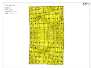
Figure 10: 50th mode shape for shallow soil site with flexible pad assumption, showing in-plane distortion of ISFSI pad.
CONCLUSIONS
The analyses performed for this paper validate the conclusions from Bjorkman et al. (2001) through the application of real-world examples. These analyses definitively conclude that the flexibility of the pad is a very important consideration that must be considered when performing the seismic structural qualification analyses for the ISFSI pads at nuclear power plants. When the rigid pad assumption is used, the results obtained for the acceleration of the cask C.G.s are expected to yield non-conservative results when compared to the flexible pad results. The modal analysis supports these conclusions in reporting twice as many critical mode frequencies for the flexible pad, as well as exhibiting much more localized flexing of the pad in the associated mode shapes. Additionally, the in-plane flexing of the ISFSI pad discovered for a select set of mode frequencies, which was not explicitly mentioned by Bjorkman et al. (2001), only further strengthens the non-conservative argument for the rigid pad assumption and why all seismic structural qualification of ISFSI pads must incorporate modeling the flexibility of the pad.
REFERENCES
Bjorkman, G. S., Moore, D. P., Nolin, J. J., Thompson, V. J. (2001). “Influence of ISFSI Design
Parameters on the Seismic Response of Dry Storage Casks,” Transactions, SMiRT 16Paper
#1601, Washington DC, August 2001.
Stevenson & Associates, SuperSASSI/PC User’s Manual Version 2.0, 2003. ANSYS, Inc., ANSYS User’s Manual – Release 14.0, 2011.
U.S. Nuclear Regulatory Commission, “Standard Review Plan for Nuclear Power Plants,” NUREG- 0800. Rev.3, March 2007.
U.S. Atomic Energy Commission, “Design Response Spectra for Seismic Design of Nuclear Power