Department of Computer Science
University College London
University of London
Software Agent Architecture for Consistency Checking
of Distributed Documents
Danila Stanislavovich Smolko
Submitted in partial fulfilment o f the requirements
for the degree of Doctor of Philosophy
at the University o f London
ProQuest Number: U642671
All rights reserved
INFORMATION TO ALL USERS
The quality of this reproduction is dependent upon the quality of the copy submitted. In the unlikely event that the author did not send a complete manuscript and there are missing pages, these will be noted. Also, if material had to be removed,
a note will indicate the deletion.
uest.
ProQuest U642671
Published by ProQuest LLC(2015). Copyright of the Dissertation is held by the Author. All rights reserved.
This work is protected against unauthorized copying under Title 17, United States Code. Microform Edition © ProQuest LLC.
ProQuest LLC
789 East Eisenhower Parkway P.O. Box 1346
Abstract__________________________________
T he size and com plexity o f current softw are system s often n ecessitates distributed and cooperative d evelopm ent by num erous participants. T his thesis investigates the problem o f m anagem ent o f co n sisten cy relations betw een docum ents in the softw are engineering dom ain, w h ich are cooperatively develop ed in such distributed setting. T he thesis builds on related w ork in expression o f con sisten cy relations by m eans o f co n sisten cy rules, and expands on the fram ework for centralised co n sisten cy link
generation to transparently provide the developers w ith in con sisten cy identification services at distributed locations.
T his thesis elaborates a con sisten cy fram ework, w h ich enables co n sisten cy checks to be carried out at location s o f the docum ents, rather than at a centralised server or repository. W e focu s on advantages that u se o f softw are agency brings to im plem entation o f this framework. T h ese advantages are realised in the d eveloped softw are agent architecture, w h ich capitalises on agent m obility for carrying out checks in the distributed environm ent.
T he thesis describes a m ethod for carrying out con sisten cy checks in crem en ta lly for the underlying con sisten cy link generation framework. Incremental checks relate in d ivid u a l docum ent updates to the current state o f the checked docum ent set. Incremental checking facilitates event-orientation o f the fram ework for distributed con sisten cy checks, w here individual update events trigger co n sisten cy checks o f related con sisten cy rules, resulting in generation o f con sisten cy links, relevant to the original changes. Inconsistent links indicate problem areas to the developers, w here further w ork m ay be needed in correction o f rem aining incon sisten cies.
T his thesis m akes a n ovel contribution to con sisten cy checking in the softw are engineering dom ain by providing the softw are agent architecture, w h ich enables distributed collaborative developm ent. Initial evaluation o f the softw are agent architecture for distributed con sisten cy checking is carried out on a sim ulation m odel.
Acknowledgements
I would like to acknowledge with sincere appreciation a number o f people, whom I ow e for helping shape this thesis. I would like to express my deep gratitude to Professor Anthony Finkelstein, my supervisor, for reassuring my confidence in achieving of the academic objectives and providing independence in research. This thesis would not have been possible without his attention and unfailing support. I am also grateful to my secondary supervisor. Dr. W olfgang Emmerich, who has provided constructive feedback for three years o f my studies and has given a detailed review to numerous reports and the thesis draft.
I would also like to thank all members o f the Software Engineering group and my fellow students, who have provided me with a very supportive environment throughout my stay at UCL. I appreciate the warm welcome into the group from Dr. Andrea Zisman and Dr. Ernst Ellmer. I am particularly grateful to Dr. Cecilia M ascolo for generous encouragement and support through the ups and downs o f the PhD, and to Nim a Kaveh - for his humour, comradeship and unconditional optimism. Credits are due to Carina A lves, Christian Nentwich, Daniel Dui, Joe Lewis-Bowen, Licia Capra, Luca Zanolin, Rami Bahsoon, Stefanos Zachariadis, my office colleagues, for creation o f a friendly and productive atmosphere. Thanks, Christian, for a timely release o f the TreeDiff tool as an open source software, and for numerous discussions o f the XLinkit framework. Joe deserves special thanks for meticulously reviewing the draft o f this thesis at a very short notice. I would also like to thank my friend Joao Oliveira for his considerate regard and kind attention in the times o f pressure.
I ow e a special gratitude to my loving partner Lucie, who believes in my abilities and has encouraged me on the way of their realisation. And, last and not least, sincere thanks go out to my parents Liliya and Stanislav for the wisdom o f their advice and for the warmth o f their hearts. Thank you so much. Mum and Dad!
Table of Contents
L IS T O F F IG U R E S A N D T A B L E S ... 10
C H A P T E R 1 IN T R O D U C T I O N ... 14
1.1 Mo t iv a t in g Sc e n a r i o...15
1.2 Co n t r ib u t io n...15
1.3 Th e siss t r u c t u r e... 16
C H A P T E R 2 R E L A T E D W O R K IN C O N S IS T E N C Y C H E C K I N G ...18
2.1 Th e Vie w p o in t s Ba c k g r o u n d...18
2 .2 Vie w p o in t-Or ie n t e d So f t w a r e En g i n e e r i n g...18
2.2.1 V ie w p o in ts...19
2.2 .2 C onsistency o f V ie w P o in ts... 19
2.2.3 C onsistency M anagem ent A c tiv itie s... 21
2 .2 .4 P o lic ie s ... 22
2.3 So f t w a r e De v e l o p m e n t En v ir o n m e n t s... 23
2 .4 Me t a-C A SE To o l s... 24
2.5 At t r ib u t e Gr a m m a r s...25
2 .6 Spec ific a t io n La n g u a g e s...26
2.6.1 C E N T A U R ... 26
2 .6 .2 P R O G R E S S ... 26
2 .6.3 G O O D ST E P ...26
2 .7 X Li n k i t... 26
2.7.1 Link G en eration ... 28
2 .7 .2 X Linkit and Distribution S u p p ort... 28
2 .7.3 Exhaustive C onsistency C h eck in g ... 28
2 .8 Su m m a r y... 29
C H A P T E R 3 R E Q U IR E M E N T S F O R D IS T R IB U T E D C O N S IS T E N C Y C H E C K I N G .. 31
3.1 St a k e h o l d e r s... 31
3 .2 Sp e c if ic a t io no f In t e r-Do c u m e n t Re l a t i o n s h i p s...32
3.3 Lo c a t io n o f Co n s is t e n c y Ru l e sa n d Th e ir Ap p l i c a b i l i t y... 32
3 .4 Dis t r ib u t e d Do c u m e n t Mo n it o r in ga n d Ch a n g e Id e n t if ic a t io n... 33
3.5 Tim in go f Co n s is t e n c y Ch e c k s...33
3 .6 In c r e m e n t a l Co n s is t e n c y Ch e c k s...33
3 .7 Re l e v a n c eo f Co n s is t e n c y Ru l e s...34
3.8 Do c u m e n t Ac c e ss Lo c a l it y... 34
3 .9 Re p r e s e n t a t io n of Re s u l t so f Co n s is t e n c y Ch e c k s... 35
3 .1 0 Up d a t eo f Re s u l t so f Co n s is t e n c y Ch e c k s...35
3.11 Ev e n t No t if ic a t io n a n d Pr o c e s s in g...35
3 .1 2 Su m m a r y... 36
C H A P T E R 4 S O F T W A R E A G E N T S A N D T H E M O B IL E A G E N T P A R A D IG M ... 38
4.1 Wh a tisas o f t w a r ea g e n t? ... 38
4 .2 Ch a r a c t e r is t ic so fs o f t w a r ea g e n t s... 40
4.2.1 W eak A g e n c y ... 40
4 .2 .2 Strong A g e n c y ... 41
4 .3 Ag e n t Mo b i l i t y... 41
4 .4 Dis t r ib u t e d Sy s t e m Co n s t r u c t io n With Mo b il e Ag e n t s... 42
4 .4.1 Traditional Distributed S y ste m s... 42
4 .4 .2 M obile A g e n ts... 44
4.5 In t e r-a g e n tc o m m u n ic a t io n... 48
4.5.1 C om m unication Prim itives...4 9 4 .5 .2 M ulti-agent C o-operation... 4 9 4.5 .3 Location Service for Distributed A g e n ts... 50
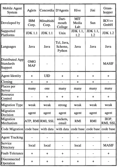
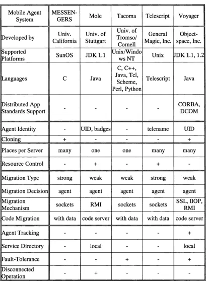
4 .6 Ta x o n o m yo f Mo b il e Ag e n t Fr a m e w o r k s...51
4 .6.1 Structure o f the T axonom y...51
4 .6 .2 C o m m en ts... 5 2 4 .7 Th e Ag lets Fr a m e w o r k...55
4 .7.1 A g e n t s ...55
4 .7 .2 Servers...56
4 .7 .3 C om m unication...57
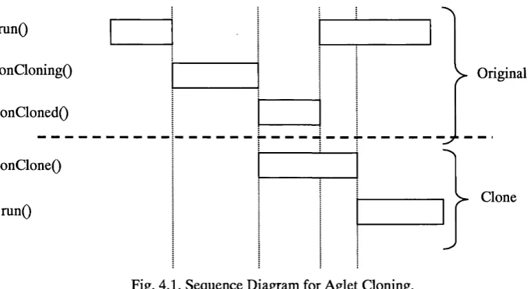
4 .7 .4 S e c u r ity ... 5 7 4.7.5 A g lets Event M odel - A gen t C loning E xam p le...57
4 .7 .6 A g lets Event M odel - A gen t M o b ility ...5 9 4 .8 Ch o ic eo fa Mo b il e Ag e n t Fr a m e w o r kf o rt h e Dis t r ib u t e d Co n s i s t e n c y... Ch e c k in g Ar c h it e c t u r e... 60
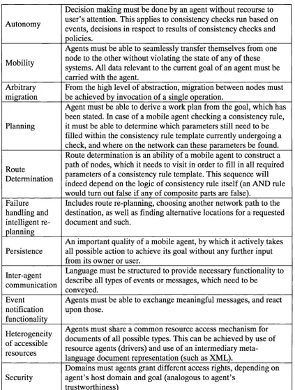
4.8.1 Requirem ents For a M obile Softw are A gen t Fram ew ork...61
4 .8 .2 Selection o f a M obile Softw are A gen t Fram ew ork... 62
4 .9 Su m m a r y... 63
CHAPTER 5 INCREMENTAL CONSISTENCY CHECKING... 64
5.1 CoNSiSTCNCY Ru l e s... 64
5.1.1 R ule E x a m p le...64
5 .1 .2 C hecking a C onsistency R u le...65
5.1 .3 R esulting C onsistency L in k s...66
5 .1 .4 Fragility o f X L ink L o ca to rs... 66
5 .2 Ex h a u s t iv e Co n s is t e n c y Ch e c k in g... 67
5.2.1 A lgorithm o u tlin e... 67
5 .2 .2 A pplication D om ain for Exhaustive C h eck s... 68
5 .3 In c r e m e n t a l Co n s is t e n c y Ch e c k in g...70
5.3.1 In itialisation ... 71
5 .3 .2 Selection o f R elevant C onsistency R u les...71
5.3 .3 Execution o f Selected R u les... 72
5 .4 Dist r ib u t io no f Co n s is t e n c y Ch e c k s... 72
5.4.1 M obile A g e n ts ...73
5 .4 .2 Distributed Incremental C onsistency C h eck in g ... 74
5 .5 In c r e m e n t a l Ch e c k in g Ch a l l e n g e s... 76
5 .6 Su m m a r y... 77
CHAPTER 6 SOFTWARE AGENT ARCHITECTURE FOR DISTRIBUTED CONSISTENCY CHECKING...79
6.1 In t r o d u c t i o n... 79
6 .2 Ar c h it e c t u r e De s c r ip t io n... 80
6.2.1 R esource Interface A g e n t...8 2 6 .2 .2 D om ain A g e n t... 83
6.2.3 G ateway D om ain A g e n t... 85
6 .2 .4 C onsistency C hecking M obile A g e n t... 86
6 .2.5 U ser Interface A g e n t ... 90
6.3 Hie r a r c h ic a l In f o r m a t io n St r u c t u r e...90
6.3.1 D ocum ent N am e T a b le ... 91
6.3 .2 D istribution o f C onsistency R u le s ...9 2 6 .3.3 A gen t Lookup T a b le ... 94
6.3 .4 Event List T a b le ...95
6.3.5 System P o lic ie s ... 96
6.4 Re-c o n f ig u r a t io n At Ru n t im e... 97
6 .5 .2 D om ain A g e n t...98
6 .5 .3 G atew ay D om ain A g e n t...99
6 .5 .4 M ob ile C onsistency C hecking A g e n t... 99
6 .5.5 U ser Interface A g e n t ... 100
6 .6 Su m m a r y... 100
C H A P T E R 7 S T A T E T R A N S IT IO N M O D E L O F T H E S O F T W A R E A G E N T A R C H I T E C T U R E ...102
7.1 In t r o d u c t i o n... 102
7 .2 Th e Mo d e l l in g Ap p r o a c h...102
7 .2 .1 Construction o f a State Transition M o d e l... 103
7 .2 .2 M od ellin g T o o l - C overs... 103
7 .3 St a t e Tr a n s it io n Mo d e lo ft h e So f t w a r e Ag e n t Ar c h it e c t u r e...104
7 .3 .1 D ocum ent active ob ject...104
7 .3 .2 R esource Interface A gent active ob ject... 107
7 .3 .3 C on sisten cy C hecking M ob ile A g en t active o b je c t... 109
7 .3 .4 D om ain A gen t active o b ject... I l l 7 .3 .5 A gen t M iddlew are active o b j e c t ...113
7 .4 Ev a l u a t io n Re s u l t s...113
7.5 Su m m a r y...118
C H A P T E R 8 S C E N A R IO S : D IS T R IB U T E D D E V E L O P M E N T O F T H E B R E A K P L A N N E R A P P L I C A T I O N ...120
8.1 In t r o d u c t i o n...120
8 .2 Ap p l ic a t io n Do m a in... 121
8.3 An Ov e r v ie woft h e Sc e n a r io s... 121
8 .4 Ap p l ic a t io n De v e l o p m e n t Te a m... 122
8.5 An a l y s isa n d De s ig n oft h e Br e a k Sc h e d u l e r Ap p l ic a t io n...122
8 .6 Sc e n a r io I: Lo c a l Co n s is t e n c y Ch e c k in ga ta Ho s t With ina Sin g l e Do m a in... 125
8 .6.1 Event: Creation o f a N e w D o c u m e n t... 125
8 .6 .2 R esponse: C onsistency C heck... 125
8 .6 .3 Result: Generated C onsistency L in k s ... 126
8 .6 .4 P rocessin g o f the E ven t... 127
8 .7 Sc e n a r io II: Dis t r ib u t e d Co n s is t e n c y Ch e c k in g Wit h ina Sin g l e Do m a i n 131 8 .7.1 D istributed Check: Generation o f C onsistency L in k s... 131
8 .7 .2 Event: D ocum ent C h a n g e ... 132
8 .7 .3 P rocessin g o f the Event by the Softw are A gent A rchitecture... 133
8 .8 Sc e n a r io III: Dis t r ib u t io no ft h e Br e a k Sc h e d u l e r Ap p l ic a t io n... 137
8 .8 .1 D istribution o f U M L M odel E le m en ts... 138
8 .8 .2 Inter-dom ain A gen t M igration P o lic ie s...139
8 .8 .3 D istributed Inter-Dom ain C on sisten cy C h e c k ... 141
8 .8 .4 Inter-D om ain D ocum ent L ocation D isc o v e r y ... 142
8 .8 .5 M ulti-A gent C ollaboration... 145
8 .8 .6 Firew alls and m obile agent secu rity ...153
8 .8 .7 D iscon n ected operation... 154
8 .8 .8 R e p lic a tio n ... 155
8 .9 Su m m a r y...156
C H A P T E R 9 IM P L E M E N T A T IO N P R O T O T Y P E ...15 7 9.1 In t r o d u c t i o n...157
9 .2 Re s o u r c e In t e r f a c e Ag e n t... 157
9 .2 .1 Startup... 157
9 .2 .2 H andled m e s s a g e s ...158
9 .3 Do m a in Ag e n t...160
9 .3 .1 Startup... 160
9 .3 .2 H andled M e ssa g es...160
9 .4.1 Startup... 162
9 .4 .2 Handled M essa g es... 162
9 .4 .3 C loning Procedure... 164
9 .4 .4 M igration... 165
9.4.5 Redundant C onsistency C h e c k s...165
9 .5 Ga t e w a y Do m a in Ag e n t...166
9.5.1 Startup... 166
9 .5 .2 Handled M essa g es... 166
9 .6 Us e r In t e r f a c e Ag e n t...166
9.6.1 Startup... 167
9 .6 .2 Handled M essa g es...167
9 .7 Se c u r it y... 167
9.7.1 U ser-level Security...168
9 .7 .2 E xecu tion -level Security o f M obile A g e n ts ... 169
9 .7 .3 M igration-level Security o f M ob ile A g e n ts ... 170
9 .7 .4 M essage-level S e c u r ity ... 171
9 .8 Su m m a r y... 172
C H A P T E R 10 E V A L U A T IO N ... 174
10.1 Qu a l it a t iv ef e a t u r e s... 174
10.1.1 E leg a n ce... 174
1 0 .1.2 M anageability... 175
10.1.3 Rule A pplicability P o lic ie s ... 176
1 0 .1.4 Flexibility and D ynam ic R econfiguration... 176
10.1.5 Grouping o f R esources Into D om ains and Support o f D om ain H ierarchies...177
1 0 .1 .6 D isconnected O peration... 178
10 .1 .7 Support for T ransactions... 179
10 .1 .8 Balance o f R equirem ents...179
10.2 Qu a n t it a t iv e Pe r f o r m a n c e Ev a l u a t io n... 180
10.2.1 Exhaustive C onsistency C heck vs. Incremental C heck...181
1 0 .2.2 Distributed C heck vs. Centralised C heck o f Distributed D o c u m e n ts... 184
10.2.3 Centrahsed Exhaustive C onsistency C heck vs. Distributed Incremental C h e c k ... 193
10.3 Su m m a r y... 194
C H A P T E R 11 C O N C L U S IO N S A N D F U T U R E W O R K ... 195
11.1 Co n c l u s io n s...195
11.1.1 T he Softw are A gent Architecture for Distributed C onsistency C h e ck in g ... 195
1 1 .1 .2 Architecture M o d e l... 195
11.1.3 Incremental C h e ck in g ...196
1 1 .1 .4 V alidation o f the A rchitecture...196
11.2 Op e n Qu e s t io n sa n d Fu t u r e Wo r k... 197
11.2.1 C onsistency C hecking F ram ew ork ... 197
1 1 .2 .2 Integration o f the Software A gen t A rchitecture... 198
11.2.3 Distributed Softw are A gent A rchitecture... 198
11 .2 .4 Incremental C h e c k in g ...198
11.3 Cl o s in g Re m a r k s... 199
B I B L I O G R A P H Y ...2 0 0 A P P E N D IX A U M L W E L L -F O R M E D N E S S C O N S IS T E N C Y R U L E S ... 2 1 0 A . 1 As s o c ia t io n s... 210
A .2 As s o c ia t io nCl a s s... 212
A .3 As s o c ia t io nEn d... 213
A .4 Be h a v io r a lFe a t u r e...214
A .5 Cl a s s ...214
A .6 Cl a s s i f i e r...215
A .8 Co n s t r a in t...218
A .9 Da t a t y p e... 218
A . 10 Ge n e r a l iz a b l e El e m e n t... 218
A . 11 Ge n e r a l iz a t io n...219
A . 12 In t e r f a c e... 220
A .1 3 Me t h o d... 221
A . 14 N a m e s ? ACE... 2 2 2 A . 15 Ty p e ... 223
APPENDIX B STATE TRANSITION MODEL PSEUDO CODE...224
B . 1 Do c u m e n t Ac t iv e Ob je c t... 224
B .2 Re s o u r c e In t e r f a c e Ac t iv e Ob j e c t... 225
B .3 Mo b il e Ag e n t Ac t iv e Ob j e c t...226
B .4 Do m a in Ag e n t Ac t iv e Ob j e c t...2 2 9 B .5 Ag e n t Mid d l e w a r e Ac t iv e Ob j e c t...230
APPENDIX C BREAK PLANNER APPLICATION: SELECTED UML DIAGRAMS 231 C. 1 An a l y s is Cl a s s Di a g r a m... 231
C .2 Dist r ib u t e d Br e a k Pl a n n e r Ap p l ic a t io n Cl a s s Dia g r a m... 23 2 C.3 Br e a k Sc h e d u l e r Ap p l ic a t io n - Us e Ca s e s...233
APPENDIX D REVIEW OF MOBILE AGENT FRAMEWORKS...234
D .l D Ag e n t s...234
D .2 Mo le ...235
D .3 Hiv e ... 23 6 D .4 Co n c o r d i a... 23 7 D .5 Gr a s s h o p p e r...238
D .6 M E S S E N G E R S ... 23 9 D .7 Ta c o m a... 24 0 D .8 Te l e s c r ip t... 241
D .9 Vo y a g e r... 2 4 2 APPENDIX E QUANTITATIVE PERFORMANCE MODEL OF THE ARCHITECTURE ...244
E .l In t r o d u c t i o n... 24 4 E .2 As s u m p t i o n s... 24 4 E.3 In it ia lf i n d i n g s... 245
E .4 Lo c a lc o n s is t e n c yc h e c k... 245
E.5 Dis t r ib u t e di n-d o m a inc o n s is t e n c yc h e c k... 24 6 E .6 Sin g l ea g e n td is t r ib u t e d c h e c ka c r o s sm u l t ip l ed o m a i n s... 24 6 E .7 Mu l t i-a g e n td is t r ib u t e dc h e c ka c r o s s m u l t ip l ed o m a i n s... 247
E.8 Th e o r e mo nm u l t ip l e-a g e n td is t r ib u t e dc o n s is t e n c yc h e c k in g...248
E .9 Th e o r e mo nm u l t i-a g e n td is t r ib u t e da n dl o c a lc e n t r a l is e dc o n s is t e n c y CHECKING... 25 0 APPENDIX F INCREMENTAL CHECKING: TECHNICAL CHALLENGES... 253
List of Figures and Tables
Ta b l e 4.1. Ta x o n o m yofm o b il ea g e n ts y s t e m s, p a r t 1... 53
Ta b l e 4.2. Ta x o n o m yofm o b il ea g e n ts y s t e m s, p a r t 2 ... 54
Fig. 4.1. Se q u e n c e Dia g r a m fo r Ag l e t Cl o n in g... 58
Fig. 4.2. Ex a m p l eoft h ec l o n in gc o d e, c r e a t in g l in k e dm a s t e ra n d c l o n ea g e n t s...59
Fig. 4 .3 . Ex e c u t io nl o go ft h ee x a m p l ec l o n in gc o d e...5 9 Fig. 4 .4 . Se q u e n c ed ia g r a m f o r Ag l e tm ig r a t io n... 60
Fig. 4.5. Re v ie wo fr e q u ir e m e n t sf o ras u c c e s s f u lm o b il ea g e n tim p l e m e n t a t io nw it h int h e CONSISTENCY MANAGEMENT DOMAIN...61
Fig. 5.1 . Co n s is t e n c y RULE: w e l l-f o r m e d n e s sc o n s t r a in tf o r "Ge n e r a l iz a t io n" e l e m e n t s. 65 Fig. 5.2 . Th isg e n e r a l iz a t io n f u l f il st h ec o n s is t e n c yc o n s t r a in t...65
Fig. 5.3. Th is g e n e r a l iz a t io nd o e sn o tf u l f ilt h e c o n s is t e n c yc o n s t r a in t... 66
Fig. 5.4 . In c o n s is t e n tl in kg e n e r a t e da sar e s u l to fac o n s is t e n c ycpœ ck...66
Fig. 5.5. Ps e u d o c o d eo ft h ee x h a u s t iv ec o n s is t e n c yc h e c k in ga l g o r it h m... 67
Fig. 5.6. Ps e u d o c o d eo ft h ein c r e m e n t a lc h e c k in ga l g o r it h m... 70
Fig. 5.7. Ps e u d o c o d efo rd is t r ib u t e din c r e m e n t a lc o n s is t e n c yc h e c k in g... 75
Fig. 6.1. a sin g l ed o m a ino fth eso f t w a r ea g e n ta r c h it e c t u r efo rd is t r ib u t e dc o n s is t e n c y CHECKING...81
Fig. 6.2. Co n s is t e n c yc h e c k in ga g e n t'sg o a l "s e l e c t" a n dt h er e s u l t - t h ea g e n t's ITINERARY...88
Fig. 6.3. Ex t r a c tf r o mt h e Do c u m e n t Na m ea n d Ty p e Ta b l e... 91
Fig. 6.4. St r u c t u r eo fa n e l e m e n to ft h e Ag e n t Lo o k u p Ta b l e...94
Fig. 6.5. Ane l e m e n to fa n Ev e n t Lis t Ta b l e, r e g is t e r in gt h ee v e n t "OnCh a n g e"... 95
F ig. 6.6. A c o n s i s t e n c y r u l e e x e c u t i o n p o l i c y e x a m p le in XML... 96
Fig. 6.7. Th es t r u c t u r eo fa r u l ee x e c u t io np o l ic y...96
Fig. 7.1 . St r u c t u r eoft h es o f t w a r e a r c h it e c t u r em o d e l... 105
Fig. 7.2. Do c u m e n ta c t iv eo b je c t; it ss t r u c t u r ea n d b e h a v io u r...106
Ta b l e 7.1. Pa r t ia lc o d e: Do c u m e n ta c t iv eo b j e c t... 106
Fig. 7.3 a. St r u c t u r eo ft h e Re s o u r c e In t e r f a c e Ag e n ta c t iv eo b je c t... 107
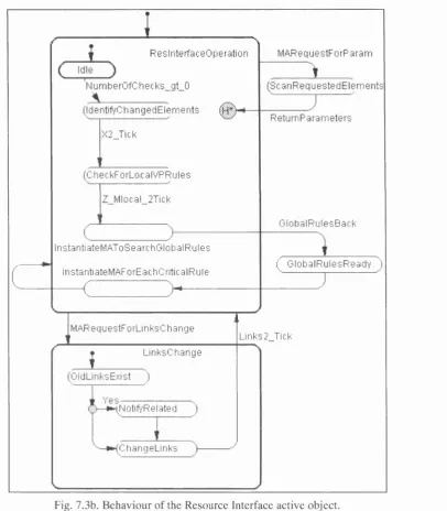
Fig. 7 .3b. Be h a v io u ro ft h e Re s o u r c e In t e r f a c ea c t iv eo b je c t... 108
Ta b l e 7.2. Pa r t ia lc o d e: Re s o u r c e In t e r f a c e Ag e n ta c t iv eo b je c t... 108
Fig. 7 .4a. St r u c t u r eo ft h e Co n s is t e n c y Ch e c k in g Mo b il e Ag e n ta c t iv eo b je c t...109
Fig. 7 .4b. Be h a v io u ro ft h e Co n s is t e n c y Ch e c k in g Mo b il e Ag e n ta c t iv eo b je c t...110
Fig. 7 .5b. Be h a v io u ro ft h e Do m a in Ag e n t a c t iv eo b je c t... 112
Fig. 7.6. Ag e n t Mid d l e w a r ea c t iv eo b je c t: itss t r u c t u r ea n d b e h a v io u r...113
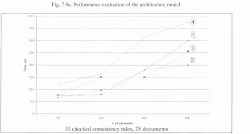
Fig. 7 .8a. Pe r f o r m a n c ee v a l u a t io n o ft h ea r c h it e c t u r em o d e l... 116
Fig. 7 .8b. Pe r f o r m a n c ee v a l u a t io no ft h ea r c h it e c t u r em o d e l (c o n t in u e d) ... 116
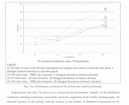
Fig. 7 .8c. Pe r f o r m a n c ee v a l u a t io no ft h ea r c h it e c t u r em o d e l (c o n t in u e d) ... 117
Fig. 7.9. Pe r f o r m a n c eo ft h em o d e la n da c e n t r a l is e dc o n s is t e n c y c h e c k e r...118
Fig. 8.1. In it ia lst r u c t u r eo ft h e C D S d o m a in...122
Fig. 8.2. Dist r ib u t io no f X M I d o c u m e n t sf o r Sc e n a r io s I a n d II (s u m m a r y) ... 122
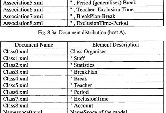
Fig. 8 .3a. Do c u m e n td is t r ib u t io n (h o s t A ) ... 123
Fig. 8 .3b. Do c u m e n td is t r ib u t io n (h o s t B )... 123
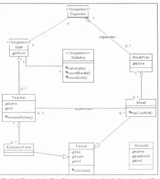
Fig. 8.4. Th e An a l y s is Cl a s s Dia g r a m c o n s id e r e d int h e Sc e n a r io s I a n d II...124
Fig. 8.5. Re l e v a n c eo f U M L w e l l-f o r m e d n e s s r u l e stom o d e le l e m e n t s... 125
Fig. 8 .6a. In it ia lv e r s io no fc l a s s Te a c h e r... 126
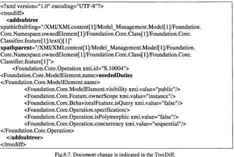
Fig. 8 .6b. In c o n s is t e n tl in kb e t w e e na n o p e r a t io nint h ec l a s sa n d t h ec l a s sd e s c r ip t o r. 127 Fig.8.7. Do c u m e n tc h a n g e isin d ic a t e dint h e Tr e eDiff... 128
Fig. 8.8. Ac t iv it ylo goft h ep r o t o t y p e: s e l e c t io no fr e l e v a n tc o n s is t e n c yr u l e s...128
Fig. 8 .9 Mo b il ec o n s is t e n c ya g e n t sr e c e iv eit in e r a r ie sf r o mt h ed o m a ina g e n t... 129
Fig. 8 .10. Ac t iv it ylo go ft h ep r o t o t y p e. Lo c a ll in kg e n e r a t io nf o r r u l e " c l" ... 130
Fig. 8 .11. Co n s is t e n tl in kb e t w e e nan a m e s p a c ea n dt h ee n d s o fa n a s s o c ia t io n...131
Fig. 8 .12. Tr e eDiff: a n a s s o c ia t io ne n de l e m e n tisa d d e dt ot h e U M L m o d e l... 132
Fig. 8 .13. Ac t iv it ylo go ft h ep r o t o t y p ea th o s t A: id e n t if ic a t io n o fc h a n g e s, r e l e v a n t RULES, PROCESSING OF LOCAL RELEVANT DOCUMENTS, MIGRATION TO HOST B ... 133
Fig. 8 .14. Se q u e n c eofc l o n in ga n d m ig r a t io n a c t io n sinad is t r ib u t e dc h e c k...135
Fig. 8 .15. Ac t iv it ylo go ft h ep r o t o t y p ea th o s t B: p r o c e s s in g o fl o c a lr e l e v a n t DOCUMENTS, LINK GENERATION, PROPAGATION OF LINKS TO HOST A ...135
Fig. 8 .16. Ac t iv it yl o go ft h ep r o t o t y p ea th o s t A: s t o r in g ofc o n s is t e n c yl in k s, d is p o s a l OF THE PARENT MOBILE AGENT...136
Fig. 8 .17. In d iv id u a lst a t is t ic sf o rt h ea g e n tf a m il y (p a r e n ta n d a l lc l o n e s) ... 137
Fig. 8 .18. Do c u m e n td is t r ib u t io nf o r Sc e n a r io III... 139
Fig. 8 .19. Mu l t i-d o m a in h ie r a r c h yo fn e t w o r kh o s t s... 139
Fig. 8 .2 0 . Su m m a r yo ft h epo lic ie sf o rin t e r-d o m a inc o n s is t e n c yc h e c k s... 141
Fig. 8 .21. Ro u t in gpo l ic ie sfo rm o b il ea g e n tin t e r-d o m a in c o n s is t e n c yc h e c k s...141
Fig. 8 .2 2 . In t e r-d o m a in l o c a t io nd is c o v e r yp r o c e s se x a m p l ef o rc o n s is t e n c yr u l e "GENERALIZATIONS"... 143
Fig. 8 .23. Re s u l t: in t e r-d o m a init in e r a r yf o rr u l e "g e nI", c h e c k e df r o mt h e C D S d o m a in. ... 143
F ig. 8 .24. X M I S o u r c e o f g e n e r a l i z a t i o n " O r g a n is e r I m p l im p le m e n t s O r g a n is e r " a n d t h e RESULTING INCONSISTENT LINK... 144
Rg. 8 .2 6 In c o n s is t e n tl in k: t w oc o pie so ft h es a m ea s s o c ia t io ne x is tint h e U M L m o d e l. . 147
Fig. 8.27. Ge n e r a t io n ofs u b-it in e r a r ie s...147
Fig. 8.28. St a g e 1 o fm u l t i-a g e n tc o l l a b o r a t io n: e x e c u t io no fs u b-it in e r a r ie s... 148
Fig. 8.29. St a g e 2 o fm u l t i-a g e n tc o l l a b o r a t io n: c o l l e c t io nin t ot h er e p o s it o r y... 148
Fig. 8.30. St a g e 3 o fm u l t i-a g e n tc o l l a b o r a t io n: g e n e r a t io no fl in k sa n d th eir PROPAGATION...149
Fig. 8.31. Co m pl et eit in e r a r yofd o c u m e n t s, r e l a t e dtoc o n s is t e n c yr u l e "n1", f r o ma l l PARTICIPATING DOM AINS...150
Fig. 8.32. Co n c a t e n a t io n ofit in e r a r ie sa n d n o d e s e t sf r o mr e d u n d a n t c o n s is t e n c y CHECKING AGENTS...151
Fig. 8.33. Pa r t ia lit in e r a r yfo rc h e c k in gr u l e "g e nI" a tt h ed is c o n n e c t e dd o m a in B C L ... 155
Fig. 10.1. Tim in g so fe x h a u s t iv ec h e c k so f U M L w e l l-f o r m e d n e s sc o n s is t e n c yr u l e s...182
Fig. 10.2. Ch e c kt im e sf o rin c r e m e n t a la n de x h a u s t iv ec h e c k s... 183
Fig. 10.3a. Ch e c kt im in g so fd is t r ib u t e dc o n s is t e n c yc h e c k sb yn u m b e ro fh o s t s... 186
Fig. 10.3b. Ch e c kt im in g s - p l a in g r a p hw itht r e n d l in e s... 186
Fig. 10.4. Pe r f o r m a n c ec o m p a r is o no fd is t r ib u t e d a n dc e n t r a l is e dc h e c k so fr u l ea1...188
Fig. 10.4b. Pe r f o r m a n c e c o m p a r is o n: p l a in g r a p hw itht r e n dl in e s...188
Fig. 10.5. Ex e c u t io no fc o n s is t e n c yr u l e: w e l l-f o r m e d n e s so f Na m e s p a c e... 190
Fig. 10.6. Ex e c u t io no fc o n s is t e n c yr u l e s: w e l l-f o r m e d n e s s o f As s o c ia t io n s...190
Fig. 10.7. Ex e c u t io no fc o n s is t e n c yr u l e s: Cl a s s e sa n d Be h a v io u r a l Fe a t u r e s...191
Fig. 10.8. Pe r f o r m a n c e o fc o n c u r r e n t m u l t i-a g e n tc h e c k s...192
Fig. 10.8b. Pe r f o r m a n c e o fc o n c u r r e n tm u l t i-a g e n tc h e c k s... 192
Fig. 10.9. Pe r f o r m a n c eo fb e s ta n dw o r s td is t r ib u t e d c h e c k in ga p p r o a c h e sc o m p a r e dw ith CENTRALISED CHECKING OF DISTRIBUTED DOCUMENTS... 193
Fig. F .l. Ex a m p l e so fc o m p l e x X Pa t he x p r e s s io n sf r o m t h e U M L r u l eb a s e... 25 4 Fig. F.2. Al g o r it h mf o rf in d in gin t e r s e c t io nb e t w e e nt w o X Pa t h e x p r e s s io n s... 255
Fig. F.3. Co n s is t e n c yr u l ese l e c t io ns c e n a r io s... 2 5 6 Fig. F.4. Re s u l t so fp r o c e s s in g X Pa t he x p r e s s io n s... 2 5 6 Fig. F.5. Al g o r it h mfo rm e r g in gl in k s e t s... 25 8 Fig. F .6a. Ex a m p l ed o c u m e n t sf o rd e m o n s t r a t io n o ft h e X Pa t h f r a g il it yp r o b l e m... 25 8 Fig. F .6b. Lin k sb e t w e e nt h et w od o c u m e n t s... 2 5 9 Fig. F.7a. Ch a n g e dd o c u m e n t s...2 5 9 Fig. F .7b. In c r e m e n t a ll in kb a s e... 2 6 0 Fig. F.8. X Pa t hu p d a t ea l g o r it h m...261
Fig. F.9. X Pa t he x p r e s s io nm a p p in gh a s h t a b l e... 261
Fi g. F. 13. Cl a s se l e m e n t, e x t r a c t e df r o m aUML m o d e l...263
Chapter 1
Introduction
The size and complexity of current software-intensive systems necessitates their distributed and
collaborative development. In this setting, a number of participants in a joint effort produce documents,
which are often required to follow certain restrictions on their format and content. These restrictions
define relations between the documents that are required to hold by a standard, a development process, a
company policy or another factor. For example, software system descriptions, expressed in the Unified
Modelling Language (UML), are required to follow the well-formedness constraints, defined by the
UML standard [OMG 2000b].
In many cases, produced documents have "overlapping" content, as they refer to common objects or
phenomena. The overlap gives rise to consistency relations between documents and their parts referred
to as document elements. In a variety of cases, the developers intend to constrain these relations, due to
the software development process used, the document structure or semantics demanded, or project
requirements. In this thesis, we use the term consistency management to describe the process, by which
existing consistency relations between overlapping documents are checked for conformance to specified
constraints.
The task of consistency management is complicated by the distribution of documents and their
concurrent collaborative development by numerous distributed participants. With the expansion of the
Internet, company intranets and distributed collaboration technologies, company-wide distribution of
developers has already become widespread, and there exists a growing trend in adoption of the
geographically distributed, Internet-scale development. Existing centralised approaches to consistency
checking cannot cope with a scenario of checking the mutual consistency of documents in the
distributed setting of this scale.
This thesis addresses the problem of checking consistency relations between distributed documents.
We build a distributed architecture, consisting of autonomous collaborating components, which
automatically provide the consistency checking service at the distributed document locations. This
architecture is proposed as an alternative to the traditional approach, where checks are inherently
centralised. The developing software agent technologies and code mobility are making feasible the
construction of the new architecture.
As a motivating scenario in this thesis, we consider the problem of consistency management in the
1.1 Motivating Scenario
As an application domain and a benchmark for the proposed software agent architecture for
distributed consistency management, we consider consistency checks between distributed software
engineering documents. A running scenario of throughout the thesis deals with the design of a break
scheduler application, discussed in [Bergner, et al. 1997]. In the scenario, a team of distributed
participants is concurrently developing on a UML model [Booch, et al. 1999] of the software
application. The scope of consistency relations, demonstrated in the scenario, is that of checking well-
formedness constraints [OMG 2000b] of the UML model throughout the development process.
Checking of well-formedness constraints of UML models has been chosen as the application
domain due to variety and complexity of the UML constraints. The approach to distribution of UML
model elements for collaborative development and distributed checks allowed us to generate evaluation
scenarios of significant scale for larger UML models.
1.2 Contribution
This thesis builds on the approach for expression of consistency relations between documents, the
concept of consistency checks of these relationships, and the method for representation of the state of
relationships between individual documents [Zisman, et al. 1999]. We draw on the recent development
of this framework - a novel XLinkit rule language [Nentwich, et al. 2001a] and the framework for
carrying out consistency checks of well-formedness consistency relations in UML models [Nentwich,
et al. 2000b].
The XLinkit framework follows the approach, which originates in software development
environments [Donzeau-Gouge, et al. 1984, G O O D STEPTeam 1994, H aberm ann and N otkin
1986, Reps and Teitelbaum 1981] and provides the facilities for carrying out centralised consistency
checks, where documents need to be stored at, or moved to, the location of the consistency checker.
The growth in distributed software development in industry and in the software engineering
community has initiated re-consideration of the centralised architectures. With respect to the existing
tools, such as XLinkit, most significant concerns arise in the scalability of the centralised approach, and
in its usability for incremental development, since consistency checks have to be initiated by a user and
upon every check, all distributed documents have to be copied to the central location and check results
need to be returned to the locations, where development takes place.
This thesis proposes a distributed architecture, where consistency checking is carried out locally at
the network hosts where documents are located. We introduce a distributed checking algorithm, which
separates checks of documents in space and time and executes at numerous locations. The approach
enables concurrent checking at numerous locations and improves efficiency and security of checks by
The architecture facilitates distribution by scaling out, through introduction of self-contained
autonomous domains and forming of a domain hierarchy, and by scaling up with the increase in a
number of hosts and documents in each domain. The concept of domains - groups of related documents
allows us to tackle large scale distribution and offer a de-centralised solution, capable of delivering an
efficient consistency checking service. Disconnected operation of autonomous domains enables us to
improve fault tolerance and achieve stability by use of persistent components. In order to fulfil its task,
the distributed architecture builds on software agency and mobility in construction the architectural
components.
In a brief summary, this thesis makes the following contributions:
Development of an architecture for distributed consistency checking, which capitalises on locality of
access to documents.
An incremental checking algorithm, which extends the capabilities of existing exhaustive checker
and provides better support for the incremental development process. We have addressed technical
challenges of extending the current non-incremental checker XLinkit to provide support for
incremental checks. Having achieved interoperability between the checkers, we consider them as
complementary and have suggested deployment scenarios for both checkers
Development of a model of the architecture, where components' operations are specified via state
charts. This model allows us to better explain component roles, to provide initial verification of the
architecture, and to give an initial estimation of its performance characteristics.
Construction of an implementation prototype of the architecture, which we have evaluated on a
number of scenarios, demonstrating its scalability and explaining in detail the features provided by
the architecture. The chosen scenarios follow distributed cooperative development of a software
application by a number of participants.
We have suggested a number of approaches to multi-agent collaboration and concurrent execution
of checks, which aim at improving performance of the distributed consistency checks, and gave
recommendations on optimal configurations of the distributed system.
We have carried out a performance evaluation of the architecture and compared it with the
centralised checking approach. This evaluation has allowed us to highlight the distribution
configurations, in which the distributed checks are most effective.
1.3 Thesis structure
Related work to consistency checking in the areas of ViewPoint software engineering, software
engineering environments, and the XLinkit consistency framework follows in Chapter 2. Chapter 3 sets
out the primary considerations - functional requirements for construction of a distributed consistency
management architecture. Chapter 4 gives an introduction to software agency and mobility concepts, on
frameworks, specify our requirements and select a framework, on which the architecture and its
prototype are constructed.
Chapter 5 introduces incremental checking development for the XLinkit framework, and considers
in detail a centralised algorithm and a distributed, incremental consistency checking algorithm. By
describing the checking process, this chapter sets a context for the following description of the
architecture.
Chapter 6 gives a high level overview of the proposed software agent architecture for distributed
consistency checking. It describes the roles of the architectural components and elaborates on fulfilment
of the functional requirements, demanded in Chapter 3, by each of the components.
A model of the architecture, outlining internal operations of each component in state transition
diagrams, is presented in Chapter 7. The model allows us to give a detailed demonstration of internal
operations of the components and their interaction, and gives an initial performance estimation of
distributed consistency checks.
A number of scenarios, occurring during the development of a UML model of a break scheduler
application, are introduced in Chapter 8. The scenarios are extensively developed for distributed checks
in different distribution configurations, where events, triggering consistency checks, actions and
interactions of components during the checks, and results of the checks are described in detail. These
scenarios are a result of deployment of an implementation prototype of the software agent architecture,
which serve as validation of the architecture.
Chapter 9 lays out the internal structure of the implementation prototype that was informally
introduced on scenarios in Chapter 8. In Chapter 9, each component of the event-driven architecture is
described in terms of event generation and handling.
The software agent architecture is evaluated in Chapter 10. Qualitative evaluation outlines
advantages and disadvantages of the architecture, and refers to the functional requirements, demanded of
the architecture in Chapter 4. Quantitative performance evaluation of the implementation prototype uses
a UML design example and contrasts the traditional centralised checker with distributed incremental
checks in the software agent architecture.
Quantitative and qualitative evaluations in Chapter 10 complement the evaluation and validation of
correctness of the implementation prototype, carried out on examples from the running scenario in
Chapter 8. Chapter 9 also plays a part in evaluation, and serves to demonstrate the event-orientation
feature of the proposed architecture.
Conclusions in Chapter 11 outline the strengths and weaknesses of the proposed software agent
architecture approach. The conclusions confirm the primary argument of this thesis, that distributed
consistency checking is effectively carried out by the proposed software agent architecture.
Chapter 2
Related Work In Consistency
Checking
Techniques for expressing and checking consistency constraints are found in many areas of
computer science. This chapter gives a summary of major work in consistency management: the
Viewpoints framework and programming and software development environments. Here we also
describe XLinkit - the framework for consistency checking, on which the software agent architecture of
this thesis builds. The review of existing methods accentuates comparisons between proposed
approaches, and aims to establish the position of the architecture, proposed in this thesis.
2.1 The Viewpoints Background
A number of researchers have worked on formal techniques for viewpoint specification [Ainsworth,
et al. 1994, Boiten, et al. 1996, Finkelstein, et al. 1992, Trappier, et al. 1995, Larsen, et al. 1995, Zave
and Jackson 1996]. Use of different abstractions when reasoning about complex systems has been
recognised as an effective way of separating concerns. Not surprisingly, many other disciplines involved
in information systems development have come up with similar approaches. View-integration in
conceptual database design has been a widely researched topic in the 1980s [Navathe, et al. 1986]. The
use of separation of views in requirements engineering even dates back to the late 1970s [Mullery 1979].
More recently, viewpoints have been proposed and researched for program development environments
[Meyers 1991] and information systems design [Baldwin 1993].
Within the software and requirements engineering communities, numerous researchers have been
working on the "multiple perspectives problem" [Finkelstein, et al. 1992, Kotonya and Sommerville
1992, Nuseibeh 1994, Reeves, et al. 1995, Spanoudakis, et al. 1997]. By this term they refer to the
problem of how to organise and guide software development in a setting with multiple actors, using
diverse representation schemes, having diverse domain knowledge and different development strategies.
A framework has been developed [Finkelstein, et al. 1992, Nuseibeh 1994] in order to address the
diverse issues related to this problem. Multi-perspective software development within this framework is
referred to as Viewpoint Oriented Software Engineering (VOSE).
2.2 Viewpoint-Oriented Software Engineering
There is a growing awareness in distributed software engineering that the development of complex
software systems can no longer be seen as a linear, top-down activity [Steen 1998]. The ViewPoint
Oriented Software Engineering framework (VOSE) [Finkelstein, et al. 1992] advocates structuring of
framework [Finkelstein, et al. 1992, Nuseibeh 1994] considers consistency relations within the context
of ViewPoints.
ViewPoint models allow developers to split up the complete specification of a complex system into
a number of viewpoint specifications, each concentrating on a particular concern or aspect of the system.
The specifications are potentially distributed, as they belong to different participants. Each viewpoint
then represents a particular abstraction, either from a stakeholder’s, or a modelling perspective.
2.2.1 ViewPoints
A ViewPoint combines the notion of 'actor', 'role' or 'agent' in the development process with the idea
of a 'perspective' or 'view', which an actor maintains. ViewPoints are defined as loosely coupled, locally
managed, distributable objects; thus containing identity, state and behaviour. A ViewPoint is more than
a 'partial specification'; in addition, it contains partial knowledge of how to develop that partial
specification.
Each ViewPoint is composed of the following components, called slots:
• The representation style defines the notation or language to be used in that ViewPoint.
• The work plan defines the actions that can be performed on specifications in the given style, and
their recommended ordering. Different kinds of actions are identified within the framework. Most
obvious are the assembly, or "editing", actions. Of particular interest to us in this thesis are
consistency checking actions, which we consider below.
• The domain is a label, identifying the area of concern of that ViewPoint.
• The specification slot contains the actual description of the identified domain, in the notation
defined in the style slot.
• The work record describes the actions that were performed on the ViewPoint specification. It thus
defines the development state of the ViewPoint.
Typically, different ViewPoints will share the same notation and development process. Creation of
a multiple-viewpoint system often occurs by instantiation of 'ViewPoint templates'. A template is a
ViewPoint, in which only the style and work plan slots have been filled in. Domain, specification and
work record slots of a template are then filled in during instantiation, thus allowing for dynamic
ViewPoint creation from templates. Creation of new ViewPoints may be the result of certain viewpoint
actions, which are a part of their work plans. Such as, a translation action would transform a ViewPoint
from one notation into another by creating a new ViewPoint-translation.
2.2.2 Consistency of ViewPoints
One of the main problems in any multiple ViewPoint approach to specification is defining and
challenging when we consider that different specification techniques may be applied to different
ViewPoints.
Consistency in this setting can be seen as a relationship between viewpoint entities. In the viewpoint
model for specification and development of software, consistency is defined as a set of syntactic
constraints. For example, the Unified Modelling Language (UML) standard [Booch, et al. 1999], based
on the Booch method [Booch 1991] for object oriented design, requires UML models to comply with a
significant number of static constraints [Appendix A] in order to be well-formed. In addition to static
constraints, techniques for tackling behavioural, or semantic consistency, which would provide
consistency management foundations for State Charts and Sequence Diagrams by means of process
algebraic specification techniques, have been studied in [Steen, et al. 1999].
The Viewpoints framework distinguishes two kinds of inconsistencies: in-ViewPoint semantic
inconsistency and inter-ViewPoint inconsistency. Consistency constraints are specified by consistency
rules [Easterbrook, et al. 1994]. In-ViewPoint consistency rules define the constraints that should hold in
order for a ViewPoint specification to be 'well-formed'; these define the static semantics for the
Viewpoint's representation style. Inter-Viewpoint rules define relationships between the representation
styles of different ViewPoints, thus identifying areas of "overlap" between the ViewPoints.
Consistency rules define partial consistency relationships between the different specification
notations. Specifications are consistent if all the rules that should hold between particular viewpoints
actually do hold. The general form of a consistency rule in [Easterbrook, et al. 1994] is the following:
VVP^ ,3VP^ : VP^diVPj^ , where VPs - is a "source ViewPoint", VPd - a "destination ViewPoint",
and 9^ is a relationship, which must hold in order for the consistency constraint to be satisfied. It is
envisaged that these consistency rules will be specified using an appropriate logic [Finkelstein, et al.
1994], where representation in first order logic is a possibility.
In-Viewpoint and inter-Viewpoint checks can uncover inconsistencies in and between specifications
that prevent a set of specifications from being globally consistent. However, self-consistency and pair
wise mutual consistency are in general not sufficient to obtain global consistency. It is suggested, that
deficiencies of such pair-wise specification of constraints can be remedied by construction of a macro-
ViewPoint, containing a graph of all other ViewPoints [Easterbrook, et al. 1994]. Constraints are then
composed on the graph, specifying relationships between its nodes.
The consistency checking actions and inconsistency handling actions are contained in the work plan
of each ViewPoint. The handling actions are resolution actions that may be performed in the presence of
inconsistency.
Although the method defining consistency in ViewPoints is very expressive, it has a number of
drawbacks. Firstly, the approach requires the designer to define all possible consistency relations
between all possible combinations of viewpoint templates to be able to identify the global consistency
status. Secondly, a case may arise that all specification notations may not be suitably expressed in the
same logic. Thirdly, the advocated development model is highly fluid and new types of viewpoint may
The consistency checking techniques, defined for the VOSE approach, are focusing mainly on the
structure of specifications. Typical inter-Viewpoint rules require that for each viewpoint of a particular
type there exists a specification component in a viewpoint of some other type.
Consistency checking techniques have been proposed, which focus more on the specification
content, in particular the specified behaviour. In the PROST report [Cowen, et al. 1993] it is suggested
that specifications are consistent if there exists a common refinement. An analysis of these variations of
consistency has resulted in a generalised definition of 'semantic consistency' based on the notion of
common refinement [Bowman, et al. 1996]. It has also been shown that this general definition
encompasses the notion of logical consistency [Bowman, et al. 1995].
An important similarity between the two approaches is that both allow inconsistencies between
viewpoint specifications to exist. This is in contrast with, for example, program development
environments [Meyers 1991], where consistency is maintained at all times. VOSE provides for
development processes to be considered explicitly. As such, in VOSE, ViewPoint templates can be
defined, which prescribe a specification notation and a work plan, where the latter includes policies for
carrying out consistency checks and inconsistency handling actions, allowing toleration of
inconsistency.
2.2.3 Consistency Management Activities
In application of the VOSE framework to management of interference relations between the
viewpoints, [Finkelstein, et al. 1996] introduce a number of interference management steps or activities.
An interference consistency relation between viewpoints arises when goals of actors or viewpoint
owners are mutually interdependent (for example, at the requirements engineering stage). [Finkelstein,
et al. 1994] admit that interference is inevitable and acceptable in system development: inevitable as a
consequence of multiple perspectives, and acceptable in support of innovation in development,
fulfilment of commitments and consideration of alternatives. As a notion, embodying a broad class of
consistency relations, interference management is subject to complexities due to difference of
viewpoints held by their owners, use of different languages or heterogeneous tools, existence of
numerous levels of development and elaboration, as well as degrees of formality and granularity.
The process of resolution of interference relationships [Finkelstein, et al. 1994] comprises the
following significant activities:
Overlap identification for recognition and classification of system components, which refer to
common objects or phenomena in the domain of discourse. This essential step sets the stage for future
definition of consistency relations between the viewpoints, and is concerned with comparison, analysis
and formalisation of the views of participants. In general, overlap identification would require some
form of user input and cannot be fully automated, since certain types of references are usually implied or
not evidently found within the components themselves. While being one of the starting steps of the
viewpoint templates, which determine the essence, types of components envisaged to be deployed in the
system.
Construction of the instances from the templates, ViewPoint instantiation, is the activity of
transformation of classified system component templates into viewpoints. The development of
viewpoint templates reflects similarities in component structure, content or function. Instantiation of
templates with specific information taken from system components enables to trace overlaps between
particular viewpoint instances.
Consistency relation construction involves the creation of consistency relationships between
different viewpoints to reflect consistency overlaps. Construction of relationships can be automatic and
dynamic (on-the-fly), on demand (for example, as a result of a performed consistency management
check), or embedded (baseline in-system relations). The relations can then be specified in terms of
particular elements of the structures of the viewpoints, and expressed in first-order logic, as overlap
between sets or in another way, which is convenient and efficient given a language that information in
the viewpoints is expressed in and the structure of this information.
The three consistency management activities described - viewpoint instantiation, overlap
identification and consistency relation construction constitute the basic activities for consistency
management, set out in the ViewPoints framework. The scope of this thesis considers overlap
identification and consistency relation construction. Leaving the viewpoint instantiation and
inconsistency resolution to the developers, we concentrate on the consistency checking activity.
2.2.4 Policies
Depending on the required level of consistency enforcement in the system, it is advantageous to set
the policies, governing execution of checks of consistency relations between the viewpoints and use of
the results of these checks for reconciliation. Policy specification is an identification and composition of
appropriate policies for execution of checks of consistency relations. Originating from the standards
compliance domain, policies are considered by us as a useful abstraction for instrumentation of
Viewpoint consistency checks. One successful realisation of the notion of policy has been developed
within the Standards Compliance Manager project [Armitage, et al. 1998, Emmerich, et al. 1999], where
each consistency relation is associated with at least one policy, which defines:
• An indication of the consistency relation, the management of which the policy is concerned
with.
• A type of event that will trigger the checking of a consistency relation. In an example, where
viewpoints are represented by documents that are being modified by developers, creation or
removal of a document and modifications to a document would constitute those events, which
should trigger checks or some consistency relations.
• A mode that the policy is applied in. In our example, in case if inconsistencies are identified, the
and allowed to continue his present activity ("warning" mode), or prevented from continuing
until viewpoints have been changed and are consistent again ("error" mode).
• A type of diagnosis that is displayed. Depending on the particulars of a system under
consideration and the type of the user, a user can be either presented with a listing of
inconsistencies found (links between related documents and document elements), or a statistical
output of the number of inconsistent elements.
A policy can be specified in terms of high-level strategies or goals. Preventive policies (such as an
"error" mode policies) involve the immediate rejection of an action, whose completion would cause the
occurrence of an interference inconsistency. Remedial policies are those in which interference triggers
resolution actions. These are diversified by toleration policies, which define the scope and extent of
toleration of interference (choice of "guidance" or "warning" mode affects the extent of toleration).
Preventive policies parallel the traditional perspective on conflict [Meyers 1991] in studies of
organisational behaviour, where conflict is a malfunction within an organisation or a group and as such
it should be avoided. By contrast, remedial policies reflect the behavioural perspective in which conflicts
are the natural result of individuals and groups each pursuing their own interests and objectives within
an organisation, and compromises need to be achieved in order to resolve them.
Policy is a useful configuration concept for consistency checks. Policies have triggered our special
interest, because they relate system events, which trigger checking of a consistency relation to the
consistency relation, to a check of this relation in an appropriate application mode and to a specific
diagnosis - result of a consistency check. Self-containability of checks results from coupling of the
results of a policy execution, which explicitly expresses the connection between the ViewPoint slots.
2.3 Software Development Environments
The consistency management technology for incremental development is provided in the syntax-
directed tools [Donzeau-Gouge, et al. 1984, Reps and Teitelbaum 1984] of the software development
environments. These environments offer document production support in such a way, that document
accesses and updates are issued in terms of commands, and each command corresponds to an increment.
Since commands in syntax-directed tools are directed towards the syntax of the underlying language, it
is possible to immediately establish the "propagation" of a consistent relation through all opened
documents (or an inconsistent relation when inconsistencies are tolerated). As a result, such tools can be
effectively used in the incremental document development process.
The commands, that syntax-directed tools perform, internally correspond to operations on a
particular abstract syntax tree [Habermann and Notkin 1986, Reps and Teitelbaum 1981]. Additional
attributes of this tree often contain semantic information. Therefore, static semantic checking of a
document, represented as an abstract syntax tree, can be carried out by evaluating the mentioned
attributes along the paths in the tree [Knuth 1968], which are computed at tool construction time based
evaluations, an artificial root is appended to the forest of abstract trees of individual documents. In this
case, consistency constraints are checked starting from the root node. The framework for consistency
management, XLinkit [Nentwich, et al. 2000b] uses a similar approach, in which constraints are checked
on a macro-graph of the trees of document elements.
Abstract syntax graphs generalise the concept of the abstract syntax trees [Johnson and Fisher 1982,
Nagl 1985] by using of non-syntactic paths for implementation of semantic relationships between
syntactically unconnected parts of different documents, which may even correspond to different types.
Representing a set of documents in a project by an abstract syntax graph allows one to carry out static
semantic analysis, checking of consistency relations and navigation between separate documents along
the paths in the project-wide graph.
Among the first syntax-directed tools developed were the Cornell Program Synthesizer [Reps and
Teitelbaum 1981], tools developed in the Mentor project [Donzeau-Gouge, et al. 1984], and the Gandalf
project [Habermann and Notkin 1986]. In terms of architectures, all of these tools maintained the
document abstract syntax trees in main memory and did not provide sufficient support for persistent
document storage. As a result, inter-document constraints could not be checked between different
document types. Additionally, none of the tools supported version and configuration management.
Next generation syntax-directed tools from the IPSEN environment [Engels, et al. 1987, Nagl 1985]
provided persistent document representation based on the proprietary GRAS database model [Lewerentz
and Schurr 1988], where all documents were stored in a single graph. This graph effectively constituted
a document "universe", where each document was represented by a subgraph with reference edges
leading to other documents' subgraphs. The architecture enabled checks of static semantics and inter
document consistency constraints. Additionally, transaction support was provided via the GRAS
transaction mechanism: any information loss was limited to the last completed command-increment. An
enhanced version of the IPSEN prototype also supported document revision control [Westfechtel 1989],
based on the functionality offered by the GRAS database system. The GRAS database system used a
proprietary data model called the graph pool, that has been explicitly defined for storing abstract syntax
graphs. While the discussed syntax-directed tools clearly benefited from the proprietary GRAS database
system providing persistent document storage, today's challenge is to be able to deploy an open standard
for document representation.
2.4 Meta-CASE Tools
Computer Aided Software Engineering (CASE) tools provide automated tool support for a range of
software engineering activities. Software engineering methods, which outline these activities, provide
techniques for specification, implementation, quality assurance, coordination, management and other
stages of the development process [Nuseibeh 1995]. Meta-CASE technology [Alderson 1991] is