University of South Carolina
Scholar Commons
Theses and Dissertations
1-1-2013
Dual-Phase Mixed Ion and Electron Conducting
Co2-Selective Permeation Membranes
Lingling Zhang
University of South Carolina - Columbia
Follow this and additional works at:https://scholarcommons.sc.edu/etd
Part of theMechanical Engineering Commons
This Open Access Dissertation is brought to you by Scholar Commons. It has been accepted for inclusion in Theses and Dissertations by an authorized administrator of Scholar Commons. For more information, please [email protected].
Recommended Citation
D
UAL-P
HASEM
IXEDI
ON ANDE
LECTRONC
ONDUCTINGCO
2-S
ELECTIVEP
ERMEATIONM
EMBRANESby
Lingling Zhang
Bachelor of Engineering Huaqiao University, 2005
Master of Engineering Tongji University, 2009
Submitted in Partial Fulfillment of the Requirements
For the Degree of Doctor of Philosophy in
Mechanical Engineering
College of Engineering and Computing
University of South Carolina
2013
Accepted by:
Kevin Huang, Major Professor
Kenneth Reifsnider, Committee Member
Xinyu Huang, Committee Member
Kyle S. Brinkman, Committee Member
ii
iii
A
CKNOWLEDGEMENTSI would like to thank my advisor, Dr. Kevin Huang who brought me to this field
and offered his knowledge, experience and his character to guide my study, research and
life. These treasures will go with me for the whole life.
I would also like to convey my sincerest appreciation to my thesis committee, Dr.
Kenneth Reifsnider, Dr. Xinyu Huang, and Dr. Kyle S. Brinkman, for their invaluable
advice and continuous help during my Ph.D study. My special thanks to my current and
former group members, Xue Li, Nansheng Xu, Xuan Zhao, Yunhui Gong, Zhengping
Mao, Qunwei Tang, Wei Tao and Kevin Rimoto, for their active and valuable
contribution and suggestions to my research.
I finally would like to dedicate this dissertation to my husband Siwei Wang, who
helps and understands me. His constant love, support and encouragement helped me get
through some of the difficult times. My special thanks to my little daughter Nikki. She
brings so many joys in my life. I would also like to thank my parents Xuehua Zhang,
hongie Jia and parents’ in law Zhigang Wang, Yumei Huang to bring us up and provided
iv
A
BSTRACTFossil fuels are the dominant energy source powering our modern society.
However, burning fossil fuels emits carbon dioxide (CO2), a greenhouse gas that can
cause climate change and ultimately threaten the survival of humanity. Effectively
mitigating CO2 emissions from the use of fossil fuels has become an intense subject of
scientific research as well as political debate in recent years. The current mainstream
technical approach to achieving that goal is to curb the emission of CO2 by capturing CO2
at point-sources and geologically storing it. The CO2 separation and capture process, the
first step toward the ultimate storage of CO2, can be applied to various stages of the
combustion of fossil fuels: post-combustion, pre-combustion and oxy-combustion
Significant technical progress in materials development and engineering design of carbon
capture systems has been made over the past decades, but the major challenge to the
commercial deployment of these technologies remains to be the energy penalty
associated with CO2 capture, compression and storage (CCS) that considerably lowers the
overall plant efficiency and ultimately increases the cost-of-electricity produced.
The state-of-the-art technologies for CO2-capture are principally based on
reversible chemical/physical sorption processes using liquid solvents and solid sorbents
as a CO2 scrubber and on size-exclusion permeation using membranes as a CO2
molecular filter. However, as aforementioned, the solvents and sorbents based technology
v
poor selectivity and incompatibility to high temperatures. As of today, only a few of
these technologies are considered commercially viable for large-scale application.
In this research, a new type of electrochemical CO2 separation membranes that
are in theory exclusively permeable and can continuously separate CO2 from either a
pre-combustion or post-pre-combustion industrial stream have been investigated. This category
of membranes functions as a mixed conductor, through the surface electrochemical
reactions of which CO2 molecules can be electrochemically transported from the targeted
stream to an isolated and concentrated stream that can be readily pressurized, transported
and stored. Since these membranes only allow the electrochemically active species to
transport through the membrane under a gradient of electrochemical potential, its
selectivity is exclusive. Furthermore, this type of membrane normally operates at
elevated temperatures in a continuous fashion, presenting excellent compatibility with
high-temperature process streams.
There are two types of mixed conductors envisioned for CO2 separation: 1) mixed
carbonate-ion and oxide-ion conductor (MOCC); 2) mixed carbonate-ion and electron
conductor (MECC). The former is more suited for pre-combustion CO2 separation while
the latter is more applicable to post-combustion CO2 separation. These CO2 separation
membranes should also be technically and economically more attractive than
conventional electrically driven, molten carbonate fuel cell based CO2 concentrator since
no external electronics are needed.
The objective of this proposed research is to systematically study the chemical
and physical properties of both MOCC and MECC membranes for selective
vi
template” technique has been demonstrated to produce a highly efficient porous ceramic
matrix containing a vast number of three-dimensional intra- and interconnected pathways
as revealed by 3D XCT for fast-ion transport. The performance of thus synthesized
MOCC membrane is remarkable, showing a permeation CO2 flux density from a
simulated fuel gas stream two orders of magnitude higher than ceramic-carbonate
systems fabricated with other methods. In addition, the CO2 flux density measured was
found to increase with the partial pressure of hydrogen in the feedstock, further verifying
the CO2 transport mechanism understood.
Second, a surface-modified dense silver-MC dual-phase MECC membrane for
CO2 separation from flue gas has been also demonstrated with improved stability. Two
pore formers were investigated to make the porous silver matrix: microcrystalline
methylcellulose and carbon black. The surface modifier is Al2O3, which was prepared by
coating Al2O3 colloidal onto the exposed surfaces of a porous silver matrix. The results
show that the use of 5% Al2O3 colloidal gives MECC the best flux density and stability
compared to the unmodified sample. Approximately 90% of the original flux values can
still be maintained after 130-hour testing for the modified membrane with
microcrystalline methylcellulose pore former, whereas only one-third of the original flux
values can be retained even after 60 hours for the unmodified membrane. For the surface
modified MECC membrane with carbon black pore former, the CO2 flux was found to
increase with time for the first 160 hours by 200%, followed by decreasing for the next
90 hours. At the 250-hour marker, the flux is still 160% of the original value. Overall,
silver-molten carbonate MECC with carbon black as a pore former and Al2O3 as a surface
vii
With the stabilized MECC membranes, we also demonstrate that the CO2 flux
follow a linear relationship with reciprocal thickness in a thickness greater than 0.84 mm,
suggesting a bulk diffusion controlling mechanism. Below 0.84 mm, the flux remains
flat, suggesting that the rate-limiting step has shifted to the surface exchange kinetics of
CO2 and O2. We also found that the CO2 flux is proportional to the linear chemical
gradient of CO2 and O2, implying that the conductivity of CO32- is dependent of PCO2 and
PO2 with a unity reaction order.
Establishing CO2 transport models and developing flux theory for MOCC and
MECC membranes is another task of this thesis project. Multifunctional CO2 transport
models encompassing 3PBs and 2PBs pathways are proposed for the first time. The CO2
flux equations suitable for dual-phase mixed conductors are developed from classical flux
theory and verified by experimental results.
Finally, we have discovered for the first time the existence of pyrocarbonate
C2O52- species on the surface of a eutectic Li2CO3 and Na2CO3 melt subject to CO2
atmosphere through a combined “DFT” and “Raman Spectroscopy” methodology. This
viii
T
ABLE OFC
ONTENTSAcknowledgements ... iii
Abstract ...iv
List of Tables ... x
List of Figures ...xi
Chapter 1 General Introduction: Materials for Carbon Dioxide Separation from Fuel and Flue Gases ... 1
1.1 Introduction ... 1
1.2 Solvent-based systems ... 4
1.3 Sorbent-based systems ... 8
1.4 Membrane-based systems ... 19
1.5 Enzyme-based system ... 32
Chapter 2 Fundamentals of Mixed Conducting CO2 Separation Membranes ... 35
2.1 Working principle of dual-pahse mixed conducting membranes ... 35
2.2 Flux Theory of Dual-Phase Mixed Conducting CO2 Separation Membranes ... 38
2.3 models for mechanistic charge transport ... 43
Chapter 3 Synthesis and Characterization of Membranes ... 48
3.1 synthesis of porous matrix and mebranes ... 48
3.2 Characterization Techniques for pourous matrix and membranes ... 57
3.3 Properties of porous matrix and membranes ... 62
ix
4.1 Background ... 89
4.2 characterizations and Properties of the MOCC dual-phase membrane ... 93
4.3 characterizations and Properties of the MECC dual-phase membrane ... 104
4.4 Conclusions ... 120
Chapter 5 In-situ Raman Spectroscopic Study of MOCC Membrane ... 123
5.1 Introduction ... 123
5.2 In-situ raman spectroscopic study ... 124
5.3 Raman spectrum ... 126
5.4 Conclusions ... 132
Chapter 6 Concluding remarks ... 134
x
L
IST OFT
ABLESTable 2.1 Two parallel ionic pathways proposed for the CO2 transport through MOCC membranes ... 45
Table 2.2 Two parallel pathways proposed for the CO2 transport through the MECC membranes ... 47
Table 3.1Summary of microstructural parameters of SDC50 (50 vol% SDC) obtained from x-ray nano-CT, FESEM and mercury porosimetry. ... 71
Table 4.1Parameters used in the calculations of theoretical CO2 flux density ... 103
Table 4.2 CO2 and O2 flux densities of different thickness of MECC membranes ... 116
xi
L
IST OFF
IGURESFigure 1.1 Image and date from US Energy Information Agency, Annual Energy
Outlook, 2011.5 ... 2
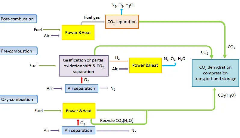
Figure 1.2 Post-combustion, pre-combustion and oxyfuel combustion processes. ... 4
Figure 1.3 The crystal structure of imidazolium ring.17... 7
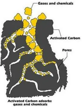
Figure 1.4 The schematic process of activated carbon adsorbing CO222 ... 9
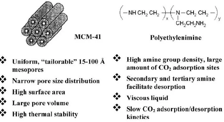
Figure 1.5 Formulation of MCM41-PEI as CO2 “molecular baskets”26 ... 11
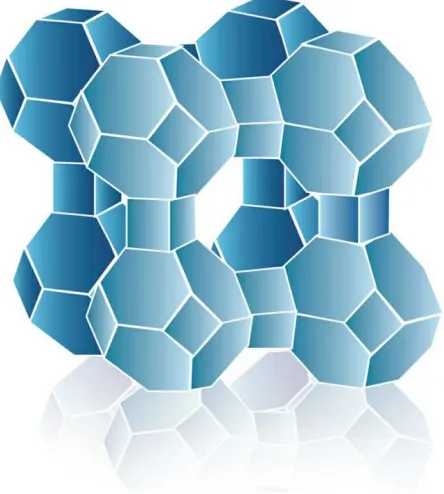
Figure 1.6 Schematic of crystal structure of Zeolite.29 ... 12
Figure 1.7 Diagram of the proposed calcination/carbonation loop.30 ... 14
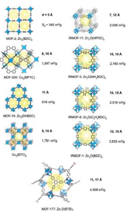
Figure 1.8 Crystal structure of MOFs examined for CO2 storage capacity at room temperature. 36 ... 16
Figure 1.9 Schematic illustration of carbonation mechanism on pure and modified Li2ZrO3. ... 18
Figure 1.10 Schematic structure of various amines modified SBA-15. 42 ... 19
Figure1.11 Transport mechanisms through macro-, meso- and microporous membranes. A) Viscous diffusion, B) Knudsen diffusion, C) Single layer adsorption, D) Multilayer adsorption & E) Molecular sieving 46 ... 22
Figure 1.12 Schematic representation of the adsorption of CO2 on the surface of SAPO-34 pore channel48 ... 24
Figure 1.13 Atomic stick representations for the frameworks of zeolite structures. (a) CHA; (b) MFI: (c) MOR; (d)DON.50 ... 25
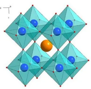
Figure 1.14 Crystal structure of ABO3; the yellow ball represents A, the blue balls represent B and the red balls represent O. ... 28
xii
Figure 1.16 Schematic of the Carbozyme permeation process for CO2 capture.9 ... 34
Figure 2.1 Schematic and working principles of the mixed conducting electrochemical CO2 separation membranes: (a) MOCC; (b) MECC ... 36
Figure 2.2 A 3D schematic illustrating electrochemical reaction occurring at 3PBs to 2PBs in dual-phase MOCC membranes; SDC=Sm2O3-doped CeO2; MC=molten carbonate ... 45
Figure 2.3 Schematic illustrations of two parallel ionic/electronic pathways for electrochemical CO2 transport taking place at 3PBs and 2PBs in MECC exposed to CO2 -O2 atmosphere. ... 46
Figure 3.1 Schematic illustrating individual steps for making porous SDC solid oxide matrix via sacrificial template method. (a) SDC-NiO composite; (b) SDC-NiO composite powder; (c) sintered SDC-NiO composite ceramic; (d) reduced SDC-Ni ceramic; (e) SDC porous ceramic after chemical removal of elemental Ni phase. ... 51
Figure 3.2 (a) Evolution of X-ray diffraction patterns of SDC/NiO ceramic (SDC65NiO35) with processing conditions. Physical appearances of SDC65NiO35 (b) after sintering; (c) after reduction; (d) after leaching in HNO3. ... 63
Figure 3.3 (a) cross sectional view of SDC65 porous structure by FESEM; (b) 3D X-ray computed tomographical view of SDC65 internal porous structure;... 64
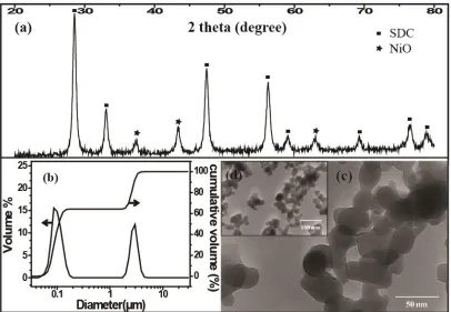
Figure 3.4 (a) XRD pattern, (b) pore size distribution, (c) higher magnification and (d) lower magnification of TEM images of SDC60/NiO40 calcined at 600oC for 4 h. ... 65
Figure 3.5 (a) FESEM image of SDC50/NiO50 sintered at 1400oC for 10 h; the corresponding elemental mappings: (b) Ce ; (c) Sm; (d) Ni. ... 66
Figure 3.6 Evolution of X-ray diffraction patterns of SDC50/NiO50 with processing steps. Physical appearances of SDC50/NiO50: (c) after sintering; (d) after reduction; (e) after chemical leaching. ... 67
Figure 3.7 (a) 3-D X-ray tomographical view and 2-D cross-sectional views at (b) low magnification and (c) high magnification; (d) Pore size distribution of SDC50/NiO50 porous matrix sintered at 1500oC. ... 69
xiii
Figure 3.9 FESEM images of SDC65/NiO35 ceramics sintered at (a)1200; (b)1250; (c) 1300; (d)1350; (e)1400; (f)1450; (g)1500; and (h) 1550oC. Plots of pore size distribution are shown in (A)-(H), corresponding to (a)-(h). ... 73
Figure 3.10 Plot of porosity and median pore size of SDC65/NiO35 as a function of sintering temperature. ... 74
Figure 3.11 Plot of porosity as a function of volume fraction of NiO in SDC-NiO composite sintered at 1400oC... 75
Figure 3.12 Microstructures of fabricated porous SDC ceramics at various conditions. (a)1300oC, (b)1400oC, (c)1500oC of sample SDC60NiO40; (d) SDC65, (b) SDC60, (e) SDC50, all sintered at 1400oC. ... 76
Figure 3.13 (a) Microstructure and (b) pore size distribution of a porous Ag matrix; (c) microstructure and (d) EDS compositions of a porous Ag matrix coated with 5% Al2O3 colloidal... 77
Figure 3.14 The microstructure of the fracture of a porous Ag matrix created by carbon black. ... 78
Figure 3.15 (a) Microstructure and (b) EDS compositions of a porous Ag matrix coated with 5% Al2O3 colloidal; Elemental distributions of Ag matrix with 5% Al2O3 colloidal (c) Ag mapping and(d) Al mapping. ... 79
Figure 3.16 (a) Cross sectional view of an SDC65/MC fracture; EDS showing the MC phase (d) and the SDC phase (e) in the SDC65/MC MOCC. ... 80
Figure 3.17 AC impedance spectra of SDC65/MC measured in dry air at three representative temperatures ... 81
Figure 3.18 Plots of the effective ionic conductivity of SDC60/MC, SDC65/MC and SDC70/MC as a function of temperature in dry air. ... 82
Figure 3.19 SDC65/MC as a function of temperature and atmospheres. ... 83
Figure 3.20 Microstructure and elemental distributions of a MOCC based on a SDC60 (60vol% SDC) porous matrix. (a) FESEM image; (b) Ce mapping; (c) Na mapping; (d) Sm mapping. Note: Li is too light to be detected by EDX. ... 85
Figure 3.21 SEM, SEM-BSE images of (e) the pristine Ag-MC MECC and (f) the MECC coated with 5% Al2O3 colloidal ... 86
Figure 4.1 Schematic of the membrane permeation reactor by Wade et al69 ... 90
xiv
Figure 4.3 Schematic of the high temperature CO2 permeation set up used by Anderson et
al. (1) CO2 cylinder, (2) Argon cylinder, (3) Helium cylinder, (4) Mass flow controllers, (5) Sweep/purge tube, (6) Feed tube, (7) Outer tube, (8) Inner tube, (9) Dual-phase membrane, (10) Furnace, (11) Permeate, (12) Retentate, and (13) GC.87 ... 92
Figure 4.4 Schematic of the CO2 permeation cell configurations. (1) CO2 cylinder; (2) Nitrogen cylinder; (3) Hydrogen cylinder; (4) Helium cylinder; (5) Mass flow controllers; (6) Furnace; (7) Thermocouple; (8) Al2O3 support tube; (9) Outer feed tube; (10) Inner feed tube; (11) MOCC membrane; (12) Gas chromatography (GC). ... 95
Figure 4.5 (a) CO2 flux density as a function of temperature and (b) Arrhenius plots of CO2 flux density. MOCC-A: 70vol%SDC-30vol%MC; B: 65vol%SDC-35vol%MC; C: 60vol%SDC60 -40vol%MC; D: 50vol%SDC-50vol%MC. ... 97
Figure 4.6 Dependence of CO2 flux density of MOCC-A on H2-concentration at 650oC98
Figure 4.7 Carbon formation domain for a H2-CO2-N2 system determined by thermodynamic analysis... 100
Figure 4.8 Comparison of CO2 permeability of the MOCC developed in this study with LSCF-MC, YSZ-MC and CGO-MC membranes available in the literature. Letters A through D have the same meanings as those in Fig. 4-5 (a). ... 101
Figure 4.9 Comparison of the measured CO2 flux density with theoretical calculations using existing flux transport model. Letters A through D have the same meanings as those in Fig. 4-5(a). ... 102
Figure 4.10 Schematic of the CO2 permeation cell configurations. (1) CO2 cylinder; (2) oxygen cylinder; (3) nitrogen cylinder; (4) helium cylinder; (5) mass flow controllers; (6) furnace; (7) inner feed tube; (8) second short alumina tube; (9) MECC membrane; (10) silver paste; (11) thermocouple; (12) supporting alumina tube; (13) inner sweep tube; and (14) gas chromatography (GC). ... 106
Figure 4.11 (a) CO2 flux densities of Sample-A, Sample-B, and Sample-C as a functional of temperature; (b) Arrhenius plots of CO2 and O2 flux densities of Sample-A and Sample-B; (c) CO2 and O2 flux densities of Sample-B as a functional of temperature. . 110
Figure 4.12 (a) Long-term stability of CO2 and O2 flux densities of Sample-A and -B measured at 650oC; Microstructures of (b) Sample-B and (c) Sample-A after long-term stability test. ... 111
xv
Figure 4.14 Microstructure and elemental distributions of Sample-B after a long-term stability test (a) SEM image; (b) Ag mapping; (c) Al mapping; and (d) K mapping. Note: Li is not detectable by EDS. ... 112
Figure 4.15 (a) CO2 flux densities of Sample-A and Sample-B as a functional of temperature; ... 114
Figure 4.16 CO2 and O2 flux densities of MECC membrane as a function of the reciprocal of thickness at 600 oC. ... 115
Figure 4.17 CO2 and O2 flux densities of MECC membrane with the thickness of 1.21 mm as a function of CO2 and O2 chemical gradient at 550 oC. (a) with natural logarithm relationship; (b) with a linear relationship ... 118
Figure 4.18 Long-term stability of CO2 and O2 flux densities of a MECC membrane measured at 650oC. ... 119
Figure 4.19 Microstructure and elemental distributions of Sample-B after a long-term stability test (a) SEM image; (b) Ag mapping; (c) Al mapping; and (d) K mapping. Note: Li is not detectable by EDS. ... 119
Figure 5.1 (a) The Raman spectra of (Li/Na)2CO3 in the region of 650-1850 cm-1 as a function of temperature in CO2 atmosphere; (b) Magnified view in the region of 1,000-1,150 cm-1 ... 127
Figure 5.2 Raman spectra of molten (Li/Na)2CO3 measured as a function of atmosphere at 525oC ... 129
1
CHAPTER 1GENERAL INTRODUCTION:MATERIALS FOR CARBON DIOXIDE SEPARATION
FROM FUEL AND FLUE GASES
1.1INTRODUCTION
Fossil fuels are the dominant energy source powering our modern society, largely
due to their competitive cost and wide accessibility. However, burning fossil fuels emits
carbon dioxide (CO2), a greenhouse gas that can cause climate change and ultimately
threaten the survival of humanity. An alarming statistic shows that nearly 40% of 5.8
billion metric tons of the total US anthropogenic CO2 emissions in 2008 was resulted
from burning fossil fuels for 71% of the total U. S. electricity generation.1, 2 From Annual
Energy Outlook of 2012 (shown in Fig.1.1), fossil fuel full consumption is still 78% of
total US energy use in 2035. Effectively mitigating CO2 emissions from the use of fossil
fuels has, therefore, become an intense subject of scientific research as well as political
2
There are four general strategies currently being considered for the abatement of
CO2 emissions: demand-side conservation, supply-side efficiency improvement, potential
increase in nuclear and renewable energy supplies, and implementation of carbon capture
and storage (CCS) technology into existing fossil-fueled power plants3, 4. Of all the
options, CCS is regarded as the sole practical near-term solution to effectively stabilize
atmospheric CO2 concentration3.
3
To realize the ultimate CCS, separation and capture of CO2 from a CO2
-containing industrial process stream is the first step. The CO2 capture technologies
currently being developed and demonstrated for existing fossil-fueled power plants are
primarily targeting three different emission sources: post-combustion, oxyfuel
combustion and pre-combustion6-8, 3 (see Fig. 1.2). The pre-combustion CO2
capture/separation is more suited for integrated gasification combined cycle (IGCC) or
natural gas combined cycle (NGCC) power plants where CO2 is separated from a mixture
of CO2 and H2 to allow final combustion to take place in pure H2.9, 10 The significant
advantages of pre-combustion capture are that the higher component concentrations and
elevated pressures can reduce the energy penalty of the capture process to 10–16%,
roughly half that for post-combustion CO2 capture.11 A further advantage is that
pre-combustion technology generates a hydrogen-rich fuel, which can be used as a chemical
feedstock for fuel cell power generation, and/or for the development of a hydrogen
economy.12 The post-combustion and oxy-combustion CO2 captures are more applicable
to conventional pulverized coal-fired (PC) and natural gas-fired power plants where CO2
is separated from N2-concentrated flue gas after fossil fuels are combusted in air4.
Post-combustion CO2 separation is realized at relatively low temperature from a gaseous
stream at atmospheric pressure and with low CO2 concentration. SO2, NO2 and O2 may
4
in pure oxygen separated from are, producing a stream of CO2 and H2O mixture for easy
CO2 capture. 13
Figure 1.2 Post-combustion, pre-combustion and oxyfuel combustion processes.
1.2 SOLVENT-BASED SYSTEMS
1.2.1 Amine absorption process
The solvent-based absorption processusing amine solutions such as
monoethanolamine (MEA) to capture CO2 is a commercialized technology used in
natural gas industry. It is a nonselective solvent to remove acidic gas impurities (such as
H2S, CO2) from natural gas stream developed over 60 years ago.14 MEA reacts with CO2
5
aqueous phase chemical reactions involved in the MEA-water-CO2 system can be
expressed by:
H O OH O
H2 3
2
(1-1)
2 3 3
2 2H O H O HCO
CO
(1-2)
2
3 3
2
3 H O H O CO
HCO (1-3) MEA O H O H
MEA 2 3 (1-4)
Because of these reactions, amines are able to capture CO2 from streams with low
CO2 partial pressure. The CO2-rich MEA solution is then set to a stripper where it is
reheated to release almost pure CO2. The MEA technology is commercially mature and
can be easily retrofitted into existing power plants. But it still suffers some drawbacks:
high energy penalty required for solvent regeneration and necessary use of inhibitors to
control corrosion and oxidative degradation due to residual oxygen in the flue stream.9
Improvements to amine-based systems for CO2 capture are currently being
pursued by a number of process developers. Fluor’s Econamine FG Plus is a proprietary
acid gas removal system that has demonstrated greater than 95% availability with natural
gas fired power plants, specifically on a 350 ton/day CO2 capture plant in Bellingham,
MA. It is currently the state-of-the-art commercial technology baseline used for
comparing other CO2 capture technologies. Mitsubishi Heavy Industries (MHI) has
developed a new absorption process, referred to as KS-1. A key factor in this
6
flue gas.15 R&D pathways to improved amine-based systems include modified tower
packing to reduce pressure drop and increase contacting, increased heat integration to
reduce energy requirements, additives to reduce corrosion and allow higher amine
concentrations, and improved regeneration procedures.
1.2.2 Ionic liquid
Ionic liquids are organic salts, a class of physical solvents which are known to be
selective for CO2 absorption.16 They comprise of combinations of large organic cations
and smaller inorganic anions and are typically viscous liquids at near room temperature.
The CO2 solubility and selectivity can be tuned by choice of cation, anion and
substituents. The advantages for ionic liquids of CO2 capture is the minimal energy
required for solvent regeneration. The capacity is directly proportional to the partial
pressure of CO2 and improves at pressures above 1–2 bar. For this reason, ionic liquids
were initially proposed for pre-combustion applications. Due to some ionic liquids react
with CO2 as well as SO2 in a chemisorption mechanism, the other advantage is that
liquids can simultaneously serve to remove CO2 and SO2. A second step to separate CO2
from SO2 is needed. Take alkylimidazolium-based ionic liquids as an example, CO2
organizes strongly about the [PF6] anion in a “tangent-like” configuration that maximizes
favorable interactions, but is more diffusely distributed about the imidazolium ring (see
7
Figure 1.3 The crystal structure of imidazolium ring.17
1.2.3 Alkaline Salt (Carbonate-based system)
Alkaline salts such as sodium and potassium salts of carbonate, phosphate, borate
arsenite and phenolate have been developed for CO2 separation. The most common salt
used in the industry has been sodium carbonate and potassium carbonate.18 The sodium
carbonate absorbsCO2 via following chemical reactions:
) ( 2
) ( )
( 2 2 3
3
2CO s CO g H O NaHCO s
Na (1-5)
The primary advantages of these materials are low cost and minimal degradation.
8
CO2 separation. Vacuum stripping for solvent regeneration has been used, and vapor
recompression may be required. A major advantage of carbonates over amine-based
systems is the significantly lowered energy required for regeneration. However, sodium
and potassium carbonate aqueous solutions have a number of problems in practice. The
solutions tend to react only relatively slowly with CO2 and the heat requirements for
regeneration of the solution is large compared to the various alkanolamine based
processes. Solution concentrations are limited by the precipitation of bicarbonate salts
and solution temperatures are high. Foaming is also reported to be a concern. Corrosion
problems may be severe depending on input gas composition, but various corrosion
inhibitors have been employed effectively in some circumstances.19
1.3 SORBENT-BASED SYSTEMS
1.3.1Activated carbons
Activated carbons are solid sorbents with high porosity, especially micro- and
mesopores, which are used in a wide range of household, medical, industrial, military and
scientific applications, including gas-phase and liquid-phase processes. The principle of
activated carbons adsorbing CO2 is schematically illustrated in Figure 1.4. The activation
process together with the intrinsic nature of the precursors strongly determines the
adsorption characteristics of the resulting activated carbons.20 Anthracites are a kind of
9
fine structure and relatively low cost, making them excellent raw materials for the
production of activated carbons with high microporosity.21
Figure 1.4 The schematic process of activated carbon adsorbing CO222
According to the results from Maroto-Valer group20, CO2 capture does not show a
linear relationship with the surface area. The highest CO2 adsorption capacity was 65.7
10
540 m2/g. The anthracite with the highest surface area of 1,071 m2/g only had a CO2
adsorption capacity of 40 mg CO2/g adsorbent. This could be explained by certain size
pores being effective for CO2 adsorption. Also, the NH3 treatment and polyethylenimine
(PEI) impregnation increased the CO2 capture capacity of the activated anthracites at
higher temperatures, due to the introduction of alkaline nitrogen groups on the surface.
1.3.2 Carbon molecular sieves and molecular baskets
Molecular sieves are a range of specially designed sieves that separate molecules
based on their molecular weight or molecular size. This technology is believed to be
cost-effective and can be adapted to a variety of carbon sequestration schemes23. There were
many research activities aiming to improve the CO2 adsorption by chemically treat the
molecular sieve surface. Adsorbents based on high surface area inorganic supports that
incorporate basic organic groups, usually amines, are of particular interest. The
interaction between the basic surface and acidic CO2 molecules is thought to result in the
formation of surface ammonium carbonate under anhydrous conditions and in the form of
ammonium bicarbonate and carbonate species in the presence of water.24
“Molecular basket” was first explored as a new concept by Xu et. al.25. It is a
high capacity, highly selective CO2 adsorbent. This adsorbent is based on mesoporous
molecular sieve of MCM-41 impregnated with polyethylenimine (PEI) (see Fig. 1.5). The
11
increase in PEI loading, the surface area, pore size and pore volume of the loaded
MCM-41 decrease. When the loading is higher than 30 wt%, the mesoporous pores began to be
filled with PEI and the adsorbent shows a synergetic effect on the adsorption of CO2 by
PEI. At PEI loading of 50 wt%, the highest CO2 adsorption capacity of 246 mg/g PEI is
obtained, which is 30 times higher than that of MCM-41 and is about 2.3 times that of the
pure PEI.26 This molecular basket can selectively capture CO2 for the separation of CO2
from simulated, natural gas-fired and coal-fired flue gases
12
1.3.3 Zeolites
Zeolites are crystalline aluminosilicates with uniform pore structure and a
minimum channel diameter range of 0.3-1.0 nm as shown in Figure 1.6. The presence of
molecular-sized cavities and pores make the zeolites effective as shape-selective
materials for a wide range of separation applications. Separation occurs in zeolite
membranes by both molecular sieving and surface diffusion mechanisms. Zeolites are
typically employed at elevated pressures (above 2 bar), and their adsorption capacity has
been shown to be greatly reduced by the presence of moisture in the gas, thereby
necessitating very high regeneration temperatures (often in excess of 300oC).27, 28 These
additional recovery costs for their regeneration pose a significant disadvantage.
13
1.3.4 Metal oxides
CaO/CaCO3solid sorbents can be used for CO2 separation. The basic separation
principle in these systems is depicted in Figure 1.7.30 One of the advantages of this type
of looping cycle is that it uses a very cheap and widely available regeneratable sorbent
that allows high makeup flows of fresh sorbent at a reasonable cost.31 A synergy could
exist for a cement plant and a power plant in these conditions. However, it is obvious that
lower makeup flows will be more attractive for most applications. This requires higher
circulation rates of solids between carbonator and calciner and the sorbent to operate a
larger number of cycles.
Shimizu et al.32 proposed the calcination of the sorbent by burning a fraction of
the fuel in the calciner with O2/CO2. Other calcination options are under development to
avoid the use of an air separation unit. For example, it has been proposed by Abanades et
al.33 to use heat carriers, such as sintered CaO (particle density higher than 3,000 kg/m3)
circulating between a high-temperature combustion chamber and the calciner, where they
are also separated from the sorbent (particle density below 1,800 kg/m3) by segregation.
Other indirect calcination options have been proposed by Ziock et al.34. In all these
options virtually pure CO2 can be obtained in the calciner, since no gas other than CO2
14
Figure 1.7 Diagram of the proposed calcination/carbonation loop.30
1.3.5 Metal organic frameworks
Metal organic frameworks (MOFs) are a new class of hybrid material built from
metal ions with well-defined coordination geometry and organic bridging ligands. They
are extended structures with carefully sized cavities that can adsorb CO2. MOFs have
received considerable attention during the past couple of years. This may be due to the
high mass flux, thermal stability, adjustable chemical functionalities, extra high porosity,
and availability of hundreds of well characterized materials reminiscent to zeolites.35
Over 600 chemically and structurally diverse MOFs have been developed over the past
several years. Fig. 1.8 shows a range of the most common crystal structure of MOFs.
Yaghi and co-workers have shown that MOF-177 exhibits a CO2 sorption capacity of 1.4
15
magnesium sites, Mg-MOF-74 [Mg2(DOT); DOT: 2,5-dioxidoterephthalate], has
excellent selectivity, facile regeneration, and among the highest dynamic capacities
reported for retaining CO2 in porous materials. Specifically, when Mg-MOF-74 is
subjected to a gas stream containing 20% CO2 in CH4, a percentage in the range relevant
to industrial separations, it captures only CO2 and not CH4.37 S. Couck et.al. have
demonstrated that metal-organic frameworks can be effectively functionalized with
amino groups. The presence of such functional groups together with OH groups of the
MIL-53 drastically enhances the affinity for CO2, resulting in a very large selectivity in
CO2/CH4 separations.38
1.3.6 Lithium Zirconate
Lithium zirconate (Li2ZrO3) has attracted attention as a promising sorbent for CO2
adsorption at high temperatures (in the range of 400ºC to 800ºC) due to its highly stable
adsorption reactivity and thermal stability. Carbonation and calcination are expressed by
the reversible equilibrium reaction as follows:
) ( )
( )
( )
( 2 2 3 2
3
2ZrO s CO g Li CO s ZrO s
Li
(1-6)
The CO2 capture mechanism is schematically shown in Figure 1.9. Lithium
zirconate has a high capture capacity (~4.5 mmol/g) and good stability over many
regeneration cycles. Moreover, it has high selectivity for CO2 and low affinity for N2.39
16
favorable up to 800ºC. Calcination dominates at temperatures above 800ºC. The XRD
pattern for structure modification during sorption and desorption indicates that CO2
carbonation using Li2ZrO3 is reversible.40 The limitation of Li2ZrO3 is that it can only
absorb CO2 up to 28.7% of its own weight.41
17
1.3.7 Organic/Inorganic Hybrid Materials
Recently, new organic/inorganic hybrid materials have shown great potential for
CO2 capture, resulting from an increase in the accessible number of sorption sites per
mass of sorbent. Sorbents in this category include covalently amine-impregnated silica
supports such as amine-modified silane and polymerized reactive amine on silica. The
common synthesis methods for covalently amine-impregnated adsorbents are saline
chemistry and polymerization. The schematic structures of various amines found on
amine-impregnated mesoporous silica (SBA-15) created by surface reaction and surface
polymerization, as shown in Figure 1.1042.
The grafting process of the hybrid aminosilica is achieved by accumulating
alkoxy groups from using silane chemistry on the surface silanols to create covalent
bonds to the silica surface through the breaking of Si-O-Si bonds, including organic
functionalities through substitution on the silane. These silane-modified samples can be
reformed to make large amine-loaded dendritic structures that are tethered mainly in the
18
19
Figure 1.10 Schematic structure of various amines modified SBA-15. 42
1.4 MEMBRANE-BASED SYSTEMS
The development of a membrane separator for the selective removal of CO2 in the
presence of CO, H2, H2O, and H2S (fuel gas) or N2, O2, H2O, SO2, NO, and HCl (flue
gas) would be of tremendous economic advantages. Membrane separation processes
provide several advantages over other conventional separation techniques43. First, the
20
not require any phase transformation. Second, the necessary process equipment is very
simple with no moving parts, compact, relatively easy to operate and control, and also
easy to scale-up.
1.4.1 Inorganic membranes
The advantages of inorganic membranes are that it is highly stable at high
temperatures and can be resistant to harsh conditions. Inorganic membranes can be
classified into two categories based on their microstructure: porous and dense44. In
porous inorganic membranes, a porous thin top layer is supported on a porous metal or
ceramic support, which provides mechanical strength but offers minimum mass-transfer
resistance. Alumina, carbon, glass, silicon carbide, titania, zeolite, and zirconia
membranes are mainly used as porous inorganic membranes supported on different
substrates, such as α-alumina, γ-alumina, zirconia, zeolite, or porous stainless steel. The
porous inorganic membrane can be further classified, based on their pore size
(microporous (<2 nm) or mesoporous (2 nm to 50 nm) or macroporous (>50 nm)), or
symmetry (symmetric, homogeneous structure throughout the membrane, or asymmetric,
gradual change in structure throughout the membrane).
The dense inorganic membranes (nonporous material) consist of a thin layer of
metal, such as palladium and its alloys (metallic membrane), or solid electrolytes, such as
21
transport occurs via solution diffusion method or changed particles in dense membranes.
The low permeability across the dense inorganic membranes limits its intended
applications, compared to porous inorganic membranes.45
Another form of inorganic membrane is the liquid-immobilized membrane, where
the pores of the membrane are completely filled with a liquid, which is permselective for
certain compounds. The liquid reacts with the permeating component on the feed side to
form a complex. The complex diffuses across the membrane and then release the
permeate on the product side, and at the same time coverts the liquid back to the feed
side.
There are five main transport mechanisms (shown in Fig. 1.11) by which gas
separation using porous inorganic membranes can be described. The basis of these
transport mechanism are (1) viscous flow, (2) the molecular weight (Knudsen diffusion),
(3) surface interactions (surface diffusion), (4) multilayer adsorption (capillary
condensation), and (5) the size of molecules (molecular sieving) to be separated.46
1.4.1.1 Alumina membranes
The generally mesoporous structure of alumina dictates that transport within
membranes fabricated from it will take place by a Knudsen diffusion mechanisms. Since
selectivity in this regime is limited, and the rate of diffusion is controlled by molecular
22
23
With mixtures such as CO2/N2, where the gases have similar mass, and CO2/H2,
where selectivity toward the heavier component is required, alumina is undesirable as a
membrane material.
Alumina finds its use in the separation of gases mainly as a support, where its
sound structural properties, and chemical and hydrothermal stabilities beyond 1,000 oC
make it very desirable.45 Carreon et. al. reported that alumina-supported SAPO-34
membranes as shown in Figure 1.12 had CO2/CH4 separation selectivity higher than 170,
with CO2 permeances as high as 2.0 ×10⁻⁶ mol/m2·s·Pa at 295 K and a feed pressure of
224 kPa. The membranes effectively separated CO2/CH4 mixtures up to 1.7 MPa.47
1.4.1.2 Zeolite membranes
Zeolites are inorganic crystalline aluminosilicate structures with pores of uniform
molecular dimensions. Examples of representative zeolite frameworks are shown in Fig.
1.13 The presence of molecular-sized cavities and pores make the zeolites effective as
24
Figure 1.12 Schematic representation of the adsorption of CO2 on the surface of SAPO-34 pore channel48
These cavities are interconnected by pore openings through which molecules can
pass. The electrical charge or polarity of the zeolites also functions to attract or sort
molecules. This ability to selectively adsorb molecules by size and polarity is the key to
the unusual efficiency of synthetic zeolites as the basis for separation. By tailoring the
chemistry and structure of the materials used to prepare them, synthetic zeolites can be
modified to provide a wide range of desired adsorption characteristics or selectivities, and
25
Figure 1.13 Atomic stick representations for the frameworks of zeolite structures. (a) CHA; (b) MFI: (c) MOR; (d)DON.50
For those reasons, zeolite membranes were prepared with large pores (FAU,
MOR)51, 52, medium pores (MFI, MEL, FER) 53, 54, and small pores (LTA, CHA, DDR)55,
56
. Most studies of CO2 separation have examined medium-pore zeolites such as
MFI-type and FAU-MFI-type zeolites. Their respective selectivities would be low, because the
pores of these zeolites are too large to separate CO2 from CH4 with high selectivity.
26
candidates for adsorbents that are useful for the separation of small molecules.
Small-pore zeolites, such as zeolite T, SAPO-34, and DDR, have Small-pores that have a size that is
similar to that of the CH4 molecule, but which are larger than the CO2 molecule. For that
reason, they are suitable for CO2/CH4 separation. High-silica types offer the advantage of
hydrophobicity, i. e., they retain their adsorption capacity in water.57 Other types of
zeolites suffer performance degradation from moisture attack.
1.4.1.3 Carbon membranes
Carbon membranes for gas separations are typically produced by the pyrolysis of
thermosetting polymers. The pyrolysis temperature, typically in the range of 500 to 1000
°C, depends upon the type of precursor material and dictates the separation performance
of the carbon membranes45. Pyrolysis of polymeric compounds leads to carbon material
with a narrow pore size distribution below molecular dimensions (< 1 nm), which makes
it possible to separate gases with very similar molecular sizes. The predominant transport
mechanism of most carbon membranes is molecular sieving. The selection of precursor
polymer, the membrane preparation method, and the carbonization process determine the
performance of carbon molecular sieve membranes. The mechanical stability can be
improved by supporting a thin carbon membrane on a porous support material, such as
27
applications in gas separation applications, such as separation of CO2 in flue gas
emissions from power plants.
1.4.1.4 Silica membranes
Silica is a viable starting material for the fabrication of CO2 selective membranes,
primarily because of its innate stability and easy modification of its structures. Unlike
alumina, which tends to undergo phase transition at relatively low temperature, or carbon,
which can exhibit substantial changes in pore size in oxidizing environments, silica
shows exceptional thermal, chemical, and structural stability in both oxidizing and
reducing environment. Sol-gel method and chemical vapor deposition (CVD) technique
are the most traditional ways used to prepare silica membranes.45
1.4.1.5 Perovskite oxide-type membranes
Typically, perovskites are of the form ABO3, the structure of which is shown in
Figure 1.14, where the A component and/or the B component may be doped with other
materials to enhance the stability and properties of perovskite oxide-type materials. These
ion-conductive perovskite-type oxide membranes have been extensively studied for O2
separations at elevated temperatures. The stability of perovskite type materials at very
high temperatures should attract one’s attention towards CO2 selective membranes at
28
prepared by the sol-gel method can be used to separate CO2. The separation factor of CO2
and N2 through the membrane was 1.12-1.2, which was higher than the value of the
Knudsen diffusion mechanism (0.8).58
Figure 1.14 Crystal structure of ABO3; the yellow ball represents A, the blue balls represent B and the red balls represent O.
1.4.1.5 Hydrotalcite membranes
Hydrotalcite (HT) compounds consist of layers of octahedrally coordinated
bivalent cations (e.g., Mg2+, Ni2+, Co2+, Zn2+, Cu2+) and trivalent cations (e.g., Al3+, Fe3+,
29
water59. The crystal structure of Hydrotalcites is shown in Figure 1.15. Hydrotalcites
show a spinel phase (MgAl2O4 in addition to γ-Al2O3 phase and MgO phase). After
calcination at higher temperatures, these compounds lose interlayer anions and water to
form mixed oxides that can be used as solid base catalysts (e.g., Mg-Al-O) as well as
catalyst supports60. Mixed oxides, Mg-Al-O, have also been shown to have high surface
area and good stability toward heat treatment, making them viable candidates as ceramic
membranes.
30
1.4.2 Polymeric membranes
Polymer membranes have been successfully applied for the separation of carbon
dioxide from natural gas streams. The harsh chemically reactive and high temperature
flue and fuel gases make the use of polymer membranes unlikely for these applications.
Generally, gas molecules transport through a polymeric membrane by a
solution-diffusion mechanism. For example, the CO2 permeate through hydrates
tetramethylammonium fluorid tetrhydrate membrane, [(CH3)4N]F 4H2O,62 as a kind of
facilitated transport membrane, by a solution-diffusion mechanism. Other mechanisms
include a molecular sieve effect and Knudsen diffusion63.
The terms permeability and selectivity are used to describe the performance of a
gas separation membrane. There appears to be a trade-off between selectivity and
permeability. Gas molecules tend to move through free volumes – the gaps between
polymeric structures. Because of the movement of the polymer chains, a channel between
gaps can be formed allowing gas molecules to move from one gap to another and thus gas
molecules can effectively diffuse through the membrane structure. Selective transport of
gases can be achieved by use of a polymer which forms channels of a certain size. Large
channels will allow faster diffusion of gases through a membrane at the cost of less
selectivity.
Membranes are a low cost means of separating gases when high purity is not vital.
31
which limits the use of membranes. The concentration of carbon dioxide in flue gases is
low, which means that large quantities of gases will need to be processed. The high
temperature of flue gases will rapidly destroy a membrane, so the gases need to be cooled
to below 100°C prior to membrane separation. The membranes need to be chemically
resistant to the harsh chemicals contained within flue gases, or these chemicals need to be
removed prior to the membrane separation. Additionally, creating a pressure difference
across the membrane will require significant amounts of energy.
1.4.3 Facilitated transport membranes
Facilitated transport membranes (FTM) have received a great deal of attentions in
gas separations because they offer higher selectivity and larger flux permeability.64
Higher selectivity in FTM is achieved by incorporating a carrier agent into membrane,
which reacts reversibly with the penetrating species. In addition to the solution diffusion
mechanism of the polymeric membranes, FTMs also involve a reversible complexing
reaction. The permeating species dissolves in the upstream portion of the membrane and
reacts with the carrier agent inside the membrane to form a complex. This complex
diffuses across the membrane, and then releases the permeants on the downstream side of
the membrane, while the agent is simultaneously recovered and diffuses back to the feed
side. FTMs can be in a form of fixed carrier membranes, solvent-swollen polymer
32
desirable for faster permeation rate. However, too thin membranes lack mechanical
strength and stability. It was also reported that the thinner the FTMs, the lower the
selectivity due to shorter diffusion time relative to chemical reaction time in the
membrane.65
Nakabayashi et al.66 applied hydrogel, prepared from a vinyl alcohol/acrylic
acid-salt copolymer, on a hydrophilic PVdF porous membrane by a spin coating method,
followed by heating to get cross-linkage. The cross-linked layer was immersed into a CO2
carrier solution (2 mol/l of K2CO3) to form a water-swollen-gel membrane. The gel
membrane was coated on a polydimethylsiloxane support. The authors discovered that
K2CO3had the highest permeation and separation factor and was most effective as a CO2
carrier among several carbonate salts of alkali metals studied. They reported that the
water-swollen-gel membrane was stable over 30 days. A much higher permeability and
selectivity was observed after adding crown ether, EDTA, or analogous compounds to the
K2CO3solution.
1.5 ENZYME-BASED SYSTEM
Biologically based capture systems are another potential way of improving CO2
capture efficiency. These systems are based upon naturally occurring reactions of CO2 in
living organisms. One of these possibilities is the use of enzymes. An enzyme-based
33
mammalian respiratory system, is under development by Carbozyme (see Fig. 1.16). The
process, utilizing carbonic anhydrase (CA) in a hollow fiber contained liquid membrane,
has demonstrated at laboratory-scale the potential for 90% CO2 capture followed by
regeneration at ambient conditions. This is a significant technical improvement over the
MEA temperature swing absorption process. The CA process has been shown to have a
very low heat of absorption that reduces the energy penalty typically associated with
absorption processes. The rate of CO2 dissolution in water is limited by the rate of
aqueous CO2 hydration, and the CO2-carrying capacity is limited by buffering capacity.
Adding the enzyme CA to the solution speeds up the rate of carbonic acid formation; CA
has the ability to catalyze the hydration of 600,000 molecules of carbon dioxide per
molecule of CA per second compared to a theoretical maximum rate of 1,400,00067. This
fast turnover rate minimizes the amount of enzyme required. Coupled with a low
make-up rate, due to a potential CA life of 6 months based on laboratory testing, this
biomimetic membrane approach has the potential for a step change improvement in
34
35
CHAPTER 2FUNDAMENTALS OF MIXED CONDUCTING CO2SEPARATION
MEMBRANES
2.1 WORKING PRINCIPLE OF DUAL-PAHSE MIXED CONDUCTING
MEMBRANES
In this dissertation work, two types of mixed conductors have been systematically
studied for CO2 separation from fuel and flue gases: 1) mixed carbonate-ion and
oxide-ion conductor (MOCC); 2) mixed carbonate-oxide-ion and electron conductor (MECC). The
former is deemed more suited for pre-combustion CO2 separation while the latter is more
applicable for post-combustion CO2 separation. Schematic of such mixed conducting
membranes are shown in Fig. 2.1 for (a) MOCC and (b) MECC. These mixed conducting
electrochemical CO2 separation membranes are technically and economically more
attractive than conventional electrically driven, molten carbonate fuel cell based CO2
concentrator since no external electronics are needed.
The working principle of MOCC membranes can be described as follows. At the
feed side, oxygen ions (O2-) of the oxide-ion conductor react with CO2 to form CO3
2-under the chemical gradient of CO2:
CO = O +
36
37
The formed CO32- migrate through the membrane accompanied by charge-balancing
opposite flow of O2-. At the permeate side, CO32- dissociate into CO2 and O2- via the
following reaction:
-2 2 2
3 CO +O
CO (2-2)
Overall reaction can then be expressed by:
CO2 (feed) = CO2 (permeate) (2-3)
The driving forces of the transport are partial pressure gradients of CO2 and O2 across the
membrane
The working principle of MECC can be described as follows. At the feed side,
CO2 and O2 are reduced into CO32- by combining with electrons e- from the membrane:
2 3 2
2 O 2 CO
2 1
CO e (2-4)
The formed CO32- migrates through the membrane accompanied by the charge-balancing
opposite flow of e-. At the permeate side, the transported CO32- react with H2 and CO to
form CO2 and H2O and give off large amount of recoverable heat ():
-2 2
2=CO +H O+2e H
CO23 (2-5)
-2 -2
3 +CO=2CO +2e
CO (2-6)
Overall reaction can then be written by
(permeate) CO + ) O(permeate H = (feed) O 2 1 + (permeate) H + (feed)
CO2 2 2 2 2
38 (permeate) 2CO = (feed) O 2 1 + e) CO(permeat + (feed)
CO2 2 2 (2-8)
The driving forces for the transport are partial pressure gradients of CO2 and O2
across the membrane.
2.2 FLUX THEORY OF DUAL-PHASE MIXED CONDUCTING CO2 SEPARATION
MEMBRANES
2.2.1 Background
The development of flux theory for dual-phase mixed conducting CO2 separation
membranes has followed the conventional transport theory – Wagner equation69, i. e., the
flux density is proportional to the chemical gradient of the active species. Lin et al70
derived the flux density of CO2, JCO2, of aLa0.6Sr0.4Co0.8Fe0.2O3-δ (LSCF)–carbonate dual
phase membrane (similar to MOCC) in the following form
' " 2 " ' 2 2 2 2 2 ln ) ( 4 CO CO CO CO i CO P P L F P P RT
J
(2-9)
where ε is the porosity and τ is the tortuosity factor for the LSCF matrix. Since pores in
the LSCF matrix are filled with carbonate, these two parameters determine the transport
properties of carbonate-ions. Furthermore, the geometric correction factor is also
considered as the fraction of the porous LSCF matrix. Physically, it represents the ratio of
the relative cross-sectional area for solid phase to the solid tortuosity for oxygen ion
transport in the solid skeleton of the porous LSCF matrix; ' 2 CO
P and " 2 CO
39
dioxide partial pressures (Pa) in the feed and permeate streams, respectively; L is the
membrane thickness (m). R is the gas constant, F is Faraday’s constant, T is absolute
temperature.
A similar analytical model was also derived for the flux of CO2, JCO2 (mol cm −2
s−1) through a dual-ionic system (similar to MOCC) by Zhu et. al..71 For a purely ionic
transport, the carbon dioxide flux can be written as:
' " 2
2 2
2 (1 ) ln
) 1 ( 4 CO CO o c o c CO P P L F RT J
(2-10)
where L is the membrane thickness, σc and σo are the conductivities of the CO32− and
vacancy charge carriers (O2− ), respectively; φ is the volume fraction of the carbonate
phase.
The flux density of CO2 for a MECC dual-phase membrane has been proposed as
72 : ) (ln 8 3 " 2 ' 2
2 2 d P
L F RT J CO CO P P el ion el ion CO
(2-11)
where P is the total pressure of the CO2 and O2 mixture. At the permeation temperature,
the ionic conductivity of CO32- in the molten carbonate phase is much smaller than the
electronic conductivity for the stainless-steel phase. Therefore, the conductivity
contribution term in Eq. (2-11) can be reduced to ionic conductivity only. Considering
the porosity () and tortuosity () of the metal support, and assuming CO2 pressure
40 " ' ' " 2 2 2 2 2 2 1 ) ln( 16 9 CO CO CO CO ion CO P P P P L F RT J
(2-12)
2.2.2 CO2 flux density of MOCC membrane developed in this thesis
Based on the classical transport theory, we have also derived flux equations for
MOCC and MECC dual-phase membranes from a general and generic perspective. For
bulk-diffusion controlled charge transport in homogeneous mixed conductors, the flux
density Ji of the active species I is given by:
zF
F z F z RT C D
J i i
i i i i i i i i
i 2 2
(2-13)
where Di, Ci, i and zi represent the self-diffusivity, concentration, conductivity and
charge of species i, respectively; i and i are electrochemical and chemical potentials of
species i; R, F and T have their usual meanings. Applying eq. (2-13) to a homogeneous
mixed CO32- (CO32-=1) and O2- (O2-=2) conductor, we can arrive at the following flux
expression 2 1 2 2 1 1 2 2 1 2 1 1 /z z F z J (2-14)
Considering the local chemical equilibrium CO2 + O2- = CO32-, one has
2 2 2 3 2 2 3 2 2 2 3 2 2 3 2 3 ln 4 4 1 2 2 1 CO O CO O CO CO O CO O CO
CO F P
RT F
J
J
41 Assuming that 2
3
CO and O2 are both PCO2 independent, the steady-state flux
2
3 2 CO CO J
J can be integrated across the thickness L of the membrane exposed to a
gradient of high PCO2’ and low PCO2”
' " 2 2 2 2 2 3 2 2 3 2 3 2 ln 4 CO CO O CO O CO CO CO P P F RT J
J
(2-16)
For dual-phase ceramic-carbonate mixed-ion conductors, the microstructural and
concentration effects have to be considered in the flux equation. The microstructural
factors such as porosity and tortuosity would have a direct impact on the diffusivity of
each migrating ion. The effective diffusivity of species i, Dieff, can be expressed by
i eff i D D (2-17)
On the other hand, the concentration of each species would also be changed by
the phase volume ratio. The effective concentration Cieff (volume basis) can be corrected
by
i i eff i C
C (2-18)
where is the volume fraction of carbonate phase. Substituting eqs. (2-17) and (2-18)
into eqs. (2-13 to 2-16) leads to the modified flux equation for dual-phase mixed
carbonate-ion and oxide-ion conducting membranes
42
2.2.3 CO2 flux density of MECC membrane developed in this thesis
Similarly, use of eq. (2-13) but with a substitution of O2-=1 by e-=2 leads to the
following CO2 flux density for MECC membranes:
2 1 2 2 1 1 2 2 1 2 1 1 /z z F z J (2-20)
Considering the local chemical equilibrium CO2 + 1/2O2+2e- = CO32-, one has
2 2 2 3 2 3 2
3 2 ln
1 ln
8 3
2
1 CO O
e CO
e CO
CO P P
F J J (2-21)
Assuming that 2 3
CO and eare both PCO2 and PO2 independent, the steady-state flux
2
3 2 CO CO J
J can be integrated across the thickness L of the membrane exposed to a
gradient of high PCO2’, PCO2’ and low PCO2”, PCO2”
2 2 2 2 2 2 2 2 3 2 3 2 3 2 8 3 / 1 ' ' / 1 " " e e ln O CO O CO CO CO CO CO P P P P F RT J
J
(2-22)
Considering the microstructural volumetric effects aforementioned, the final CO2
flux density for MECC membranes can be written by:
2 2 2 2 2 2 2 2 3 2 3 2 1 1 / 1 ' ' / 1 " " e e ln ) ( ) ( 8 3 O CO O CO CO CO CO P P P P L F RT J