MEENAKSHISUNDARAM SRINIVASAN, SATHISH. Timer Based Automated Object Dispenser System Design with Programmable Control. (Under the direction of Dr. Yuan-Shin Lee).
This thesis presents a new approach to automated object dispensing and their working procedures. A programmable controlled hardware assembly includes the design of movable components of mechanisms, stepper motor, timer and actuator. This machine is designed to accommodate different types and sizes of objects with a small change in the components of the machine.
Timer Based Automated Object Dispenser System Design with Programmable Control
by
Sathish Meenakshisundaram Srinivasan
A thesis submitted to the Graduate Faculty of North Carolina State University
in partial fulfillment of the requirements for the Degree of
Master of Science
Industrial Engineering
Raleigh, North Carolina 2010
APPROVED BY:
Dr. Robert Young Dr. James Wilson
DEDICATION
BIOGRAPHY
ACKNOWLEDGMENTS
I would like to express my deep appreciation and gratitude to Dr. Yuan-Shin Lee, my advisor, for the initiation of my research and for his continuous support, guidance and encouragement during the period of my academic study and research work at North Carolina State University. I am deeply indebted to his contributions in time and efforts. I would like to thank to members of my master thesis committee Dr. James Wilson and Dr. Robert Young for serving in my advisory committee.
I would like to thank to my research group mates Deyao Ren, Apichart Boonma, Yingjie Li, Manida Swangnetr, Eui Seok Kim and Plawut Wongwiwat, for their valuable suggestions, help during meetings, personal discussions and countless rides in their car. I would extend my thanks to Jason Low, Dan Leonard and Ronald Aman who helped me build the prototype, Guha Prasanna who helped me with problems in Solidworks, Kasturirangan Parthasarathy, Koushik Narayanan and Narayanan Ramanan for helping me in LaTeX issues. I would also like to thank Dr. Larry Tupler, Durham VA Medical Center for his valuable inputs and suggestions.
TABLE OF CONTENTS
LIST OF TABLES...vii
LIST OF FIGURES...viii
1 Introduction……… 1
1.1 Motivation………... 1
1.2 Research scope and objectives……….. 3
1.3 Thesis outline……… 4
2 Literature Review………... 5
2.1 Objects sorting……….. 5
2.2 Vision based sorting……….. 6
2.3 Tablet dispenser and methods………... 7
2.4 Summary………... 9
3 Methodologies for Object Sorting and Dispensing……….. 10
3.1 Important factors considered in the design….………... 10
3.2 Simple mechanisms used in sorting and separating……… 14
3.3 Summary………... 18
4 Designs and Analysis of Object Sorting and Dispensing Models……… 19
4.1 Models designed for object dispensing………... 19
4.1.1 Slider model……… 20
4.1.2 Geneva mechanism model………... 22
4.1.3 Gear driven model………... 24
4.2 Analysis of the three dispenser models……….…….. 27
4.2.1 Comparison of three models………... 27
4.2.2 Evaluation of models………... 28
4.3 Summary………. 35
5 Sorting and Dispensing System Design………... 36
5.1 Working mechanism of slider model……….. 36
5.2 Design of components………. 37
5.2.1 Circular plate ……….. 38
5.2.2 Cylindrical tube………...… 40
5.2.3 Bottom plate ………... 40
5.2.4 Slider ………... 42
5.2.5 Spring ………. 43
5.2.6 Actuator………... 45
5.2.7 Stepper motor……….. 47
5.2.8 Size converters………. 49
5.3 Circuit and wire for control……….. 50
5.4 Summary ………. 51
6 Development of Programmable Control for Automated Object Dispenser…... 52
6.1 Hardware and software interface ………... 52
6.2 Design of the programmable control system….………... 55
6.2.1 User interface development………….………... 56
6.2.2 Timer and interval algorithm ……….. 56
6.3 Control algorithm………. 56
6.4 Communicating information to users……….………….. 59
6.5 Sensors………..……… 60
6.6 Summary………... 61
7 Experiments and Results……….. 62
7.1 Working procedure………... 62
7.2 Selection of tablets ………...………… 64
7.3 Settings………. 66
7.4 Electronic notification interface ………... 67
7.5 Testing………...68
7.6 Summary ……….………. 75
8 Conclusions and Future research………... 76
8.1 Conclusions………..………... 76
8.2 Future research ………... 76
LIST OF TABLES
Table 3.1 Classification of tablets based on axial shape and tube shape ………11
Table 3.2 Tube shape and percentage distribution……….. 12
Table 3.3 Classification of tablets based on their dimensions and shape …………... 13
Table 4.1 Comparison of three models………28
Table 4.2 CAM and PAM ratings of slider the model……..……….. 29
Table 4.3 CAM and PAM ratings of the Geneva mechanism model…...……...…… 31
Table 4.4 CAM and PAM ratings of the gear driven model………...……… 32
Table 4.5 Comparison of CAM and PAM rating for three different models……….. 33
Table 4.6 Comparison of model based on the features and construction..………….. 34
Table 5.1 List of components for slider model………37
Table 5.2 Actuator specifications….………... 46
Table 5.3 Stepper motor specifications………47
LIST OF FIGURES
Figure 2.1 Tablet dispensing and packaging [Kim03] ………. 7
Figure 3.1 Pictures of different shapes and sizes of tablets... 10
Figure 3.2 Feeding device mechanisms [SC01]………... 15
Figure 3.3 Separating device mechanisms……….. 15
Figure 3.4 Mixing different parts mechanism [SC01]…...………. 16
Figure 3.5 Simple sorting mechanisms [SC01] ………... 16
Figure 3.6 Sorting by height mechanisms ………... 17
Figure 3.7 Simple separating mechanisms [SC01]………. 17
Figure 4.1 Slider model assembly ………... 21
Figure 4.2 Slider model assembly ………... 21
Figure 4.3 Slider model assembly ………... 22
Figure 4.4 Geneva mechanism assembly with components………... 23
Figure 4.5 Geneva mechanism arrangement………24
Figure 4.6 Rack and pinion arrangements………25
Figure 4.7 Rack and pinion arrangements………... 26
Figure 4.8 Rack and pinion arrangements………... 26
Figure 4.9 Gear driven model component………... 27
Figure 4.10 Pie chart of parameters for validation……….………. 34
Figure 4.11 Overall comparison of the models ………... 35
Figure 5.1 Mechanism of the slider………... 37
Figure 5.3 Circular Plate ………... 39
Figure 5.4 Circular plate -drawing ………. 39
Figure 5.5 Cylindrical tube……….. 40
Figure 5.6 Bottom plate………... 41
Figure 5.7 Bottom plate –drawing……….. 41
Figure 5.8 Different types of sliders……… 42
Figure 5.9 Drawing of slider ………. 43
Figure 5.10 Slider spring interface……….. 44
Figure 5.11 Spring specification details………. 45
Figure 5.12 Actuator used in the system………. 46
Figure 5.13 Actuator – gear system….……… 46
Figure 5.14 Stepper motor……….………. 48
Figure 5.15 Different size converters………...………...49
Figure 5.16 Cylindrical tube with size converters………... 49
Figure 5.17 Circuit diagram with connection details……….. 50
Figure 6.1 Input and output pins testing control………... 53
Figure 6.2 Stepper motor testing control………. 53
Figure 6.3 Structural outline……… 54
Figure 6.4 Hardware and software interface………54
Figure 6.5 Control algorithm flowchart……….. 58
Figure 6.6 Communication to user ………. 60
Figure 6.7 Touch sensor placed in the collecting cup ……… 61
Figure 7.2 User interface window of visual basic application ………63
Figure 7.3 Selection of routine method………64
Figure 7.4 Selection of tablets by routine method……….. 64
Figure 7.5 Selection of a tablet by interval method ………... 65
Figure 7.6 Selection of all tablets by interval method……… 65
Figure 7.7 Tablets selected for morning cycle……… 66
Figure 7.8 Tablets selected for afternoon cycle………... 66
Figure 7.9 Settings screen of a new schedule………...……... 67
Figure 7.10 Warning message while sending an E-mail...……….. 68
Figure 7.11 E-mail notification to the user ………. 68
Figure 7.12 Test message for morning tablets……… 69
Figure 7.13 Test message for afternoon tablets……….. 69
Figure 7.14 Tablets loaded in the cylinder………... 70
Figure 7.15 Actuator positions……….………70
Figure 7.16 Slider and spring compressed ………. 71
Figure 7.17 Slider with tablet loaded to dispense………71
Figure 7.18 Tablets collected at the collecting cup………. 72
Figure 7.19 Tablets selected for test scenario 1……….. 72
Figure 7.20 Tablets dispensed for the test scenario 1.…….……… 73
Figure 7.21 Tablets selected for test scenario 2……….. 73
Figure 7.22 Tablets dispensed for the test scenario 2……..….………... 74
Chapter 1
Introduction
1.1 Motivation
Sorting objects and dispensing the right objects at the right timing is very important for many different applications. These applications are used in a variety of industries ranging from food processing, textiles, pharmaceuticals and manufacturing industry with discrete components. For example, a tablet dispensary is useful for hospitals and homes. Particularly, older people need medication regularly and they sometimes forget to take their pills or tablets, due to shortness of memory. The purpose of this thesis is to design and develop an object dispensing machine to dispense tablets according to the prescription of a doctor. A software program in the computer acts as the brain of the system, controlling stepper motors and actuators. Once the objects are dispensed the system reminds the user, with a LED illuminator or buzzer sound. Details of the design and development are presented in this paper.
(a)
Patience Compliance
Almost two-thirds of Americans currently use medicines: Forty nine percent use prescription drugs and thirty percent use non-prescription medications.
The No.1 problem in treating illness today is the patient‟s failure to take prescrip-tion medicaprescrip-tions correctly, regardless of patient age
Two-thirds of all Americans fail to take part or all of their prescription medicines.
(b)
Effects of non-compliance
Twenty three percent of nursing home admissions are due to non-compliance. Ten percent of hospital admissions are due to non-compliance.
(c)
Prescriptions
About fifty percent of the 2 billion prescriptions filled each year are not taken correctly.
One third of patients take all their medicine, one third take some, one third do not take any at all (that is, their prescription is never filled).
In order to avoid these problems and improve the patient compliance, there are many products available to make it easier for the patients to remember their medication and take their medicine at the right timing. There are some models available that require lots of work from the patient side. The patient needs to sort the tablets according to the prescription and load them in proper chambers. This involves lots of work from the patient. The application of sorting and dispensing of objects can be applied in many industries, among them a few are listed here:
(a)
Applications in the textiles industries
the processing materials. This would be of great use in the garments manufacturing industry.
(b)
Application in food processing industries
In the food processing industries and the confectionery manufacturing industries, the assorted mix of their products involves sorting, dispensing and packing of the items at the right time. There is a huge need of these applications in food processing industry where sorting and dispensing of different food items is involved.
(c)
Application as pet feeding machine
In many occasions, the pets have to be left in a home for a long time during a family outing or a vacation. The dispensing system can be used as a pet feeding machine, where the discrete food items can be loaded so that the machine operates and dispenses the food to the pets on a timely schedule. The size of the pet food is a constraint here. If the size of the food is big, accommodating them needs changes in the dimension of the parts of the machine. This machine can feed for different number of days and periods so long as the food lasts.
1.2 Research scope and objectives
1.3 Thesis outline
Chapter 2
Literature Review
In this chapter, some literature review of object sorting and objects dispensing techniques are presented.
2.1 Objects sorting
Objects sorting deals with the separation of objects based on their parameters. The parameters may be physical or geometric parameters like material, shape, size, color etc. An example of objects sorting is the coin sorting and counting machine which sorts the coins based to the coin size and dispenses vouchers corresponding to coins [Mol06]. All the coins are fed into a hopper from where it passes through a rotating chamber containing holes of the sizes of different coin. The holes are arranged in ascending order in such a way that small coins fall out of chamber first through the small holes. The coins of bigger sizes are then moved towards the other end where they fall out through the corresponding holes. Finally, if there are any exceptions in the coins left, they will be collected at the end.
2.2 Vision based sorting
Software based automated sorting is of primary importance in industries today. The sensors and cameras are used as the source to collect the object‟s parameters. Image processing techniques combined with artificial intelligence are used to identify the objects. The advantages of these systems are high speed sorting, higher efficiency, high accuracy and the elimination of human involvement. An example of identifying pistachio nuts in industries using acoustics signals and a multilayer feed forward neural network classifier is discussed in [OMO09].
Some example applications of vision based sorting in industries are discussed in [CKY06]. Computer vision algorithms were used to determine the color of the fish and sort them fast. This allows non-destructive testing method. A computer vision based surface detection of apples was discussed in [LWG02]. The system captured the image of apples and further processing was done based on the results obtained by image processing technique.
2.3 Tablet dispenser and methods
Drug dispensing device serving with limited space availability was discussed in [Tak00]. Tablets and pills were arranged in a case and the case was dispensed according to the prescription. In [Kim03], the packaging of tablets and pills is done as the tablets are dropped into the bag which is sealed and packed. Figure 2.1 shows this method. A high speed counting and dispensing discussed in [Gel04]. It uses the storage compartments with a predefined number of tablets. When a request was made, the tablets were dispensed from the storage compartments without the need for counting. This eliminates the delay time needed for counting.
Another type of tablet dispenser is discussed in [Spa94]. This contains plurality of frames and housing for the tablets with vial manipulator assembly, a motor, a control and a printer to print the prescription. In [Wei91] a dispenser with non-reversing method was discussed. There is a rotating disk which can hold only one tablet during its rotation. When the disk rotates the tablet falls into the opening through the orifice, by gravity. The disk rotates in one direction so it becomes non reversible for tablet due to gravity.
In [Gir08], a small hand-held tablet dispenser with dual lever mechanism is imple-mented. It can handle only one type of tablet. This is specially designed for candy or mint. This works with force given by pressing the lid at the top which opens the lever at the bottom, and thereby dispensing one tablet at a time. In [Har76], a tablet dispenser is implemented with vertical cylindrical stack of tablets pushed at the bottom by the reciprocating pusher. In [Koo95], a tablet dispenser is developed with a rotator at the bot-tom. In [Var08], a tablet dispenser with a rotating component carrying one tablet for each rotation is discussed. The problem with this model is that it cannot work with tablets other than the circular shape. In [EJ03], a tablet dispenser is implemented with a motor on which the compartments were moved. When the compartment reaches the desired position it opens and dispenses the tablets to a collecting cup. In [Lew86], tablet dispenser primarily working on the principle of operation of a cam is discussed. It contains rotating chambers with space for multiple pills or tablets. Once loaded it rotates and dispenses tablets at one chamber. The problem with this is that the tablets need to be loaded according to the sequence of the prescription of tablets. Skipping one dosage of tablets may result in error and confusion.
In [Pea06], a vacuum pill dispenser with a counter was discussed. In this design there is a rotating vacuum disc with a counter housing which can load tablets by vacuum suction cup and the rotation places them on the pill separator which slides the pill though the opening. There is a counter placed against the pill separator to detect the pill and count the number of pills. In [KJ08], a vacuum method was used in the heavy pharmaceutical industries.
shaped, slope with number of descending steps to separate the tablets and control the flow as required. This is suitable for different types of tablets. The vibrational speed can be varied according to the requirement.
2.4 Summary
Chapter 3
Methodologies for Object Sorting and
Dispensing
While designing a system for object dispensing, many factors need to be considered. The ease of use, assembly, reusability and simple design are some of the factors to be considered in designing a system. Our objective is to design and develop an object dispensing system by taking advantage of the logical and programmable control with a software program.
3.1 Important factors considered in the design
The system should be simple in its working mechanisms. For example, a system without gears is much simpler in implementation than a system with gears.
The size of the system should be small with fewer components and easy for assembly.
(a) Capsule (b) Oval (c) Oval with edge
The system should be very easy to be used from the user‟s perspective. The cost of manufacturing should be low to make the product affordable.
This system consists of both the hardware and software components. The hardware components involve designing of components based on its working principle. The software part consists of the Visual Basic program which drives the hardware components. The most challenging part of the design is to dispense the right object. The main aim of designing such a system is to load the system with tablets and to dispense the tablets according to the prescription and the schedule given by the user. This eliminates the patient‟s burden in remembering the dosage. The major difficulty was dispensing one correct tablet from the bin. An analysis was done by analyzing different dimensions of tablets. There were around 670 different tablets available in a database provided by a hospital. Designing a common mechanism that accommodates all the different variety of tablets is a challenging task. Some examples of different shapes of tablet are shown in Figure 3.1.
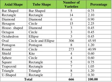
Table 3.1: Classification of tablets based on axial shape and tube shape
Axial Shape Tube Shape Number of
Varieties Percentage
Bar Shaped Bar Shaped 5 0.75
Rectangle Rectangle 14 2.10
Diamond Diamond 6 0.90
Hexagon Circle 15 2.25
House- shaped Diamond 3 0.45
Octagon Circle 3 0.45
Octahedron Ellipse 3 0.45
Oval Circle and Ellipse 306 45.95
Pentagon Pentagon 8 1.20
Round Circle 273 40.99
Shield Kite 4 0.60
Sphere Circle 4 0.60
Square Rectangle 5 0.75
Trapezoid Rectangle 7 1.05
Triangle Triangle 8 1.20
U-Shaped Rectangle 2 0.30
Considering all these different shapes and sizes, the tablets were categorized into groups based on the shapes. There were fifteen different types of shapes. Table 3.1 shows the different types of tablets available. It also shows a list of tube shapes that can be used to accommodate them.
The range of the height was in a permissible range to accommodate with few changes to the system design. The height of tablets is chosen as a base for further design. Table 3.2 shows the distribution (in %) of tablets with respect to the tube shape. By classifying these tablets according to the thickness and shapes, different tablets can be adopted into several different tubes in the design.
Table 3.2: Tube shape and percentage distribution
Table 3.2 shows eight major tube shapes with various dimensions required to accommodate the range of different shapes of tablets. Table 3.3 shows the classification of tablets based on the Z dimension i.e. the height of tablets.
Tube shape Axial shapes covered Percentage of
tablets
Bar shaped Bar shaped 0.75
Rectangle Rectangle, Trapezoid, Square 4.20
Diamond Diamond 1.35
Circle
Hexagon, Octagon, Oval, Round,
Sphere 67.27
Ellipse Octahedron, Oval 23.43
Pentagon Pentagon 1.20
Kite Shield 0.60
Triangle Triangle 1.20
Table 3.3: Classification of tablets based on their dimensions and shape.
S.no Axial Shape
X (dimension in mm) Z (dimension in mm) No. of varieties
1 Oval 9 3 15
2 Rectangle, Concave Rectangle, Pentagon, Oval, Round, Bar-Shaped 4 -15 4 27
3 Bar-Shaped, Oval, Trapezoid, Rectangle, Concave Rectangle, Hexagon, Diamond 3 - 15 5 93
4
Oval, Bow-Shaped, Concave
Rectangle,House-shaped,Octahedron,Pentagon,Round,Hexagon,Sphere,Square 6- 15 6 116
5 Oval,Trapezoid,Hexagon,Diamond,U-Shaped,Rectangle,Pentagon,Shield 7 - 21 7 135
6 Oval, Round, Rectangle, Diamond, Trapezoid, Bow-Shaped, Square 8- 20 8 124
7 Rectangle, Oval, Hexagon, Triangle. Round, Round, Octagon
7 - 10,15,16,
18 - 20,23 9 55
8 Oval, Triangle, Diamond, Round 10,13-22 10 54
9 Oval, Triangle, Round, Pentagon 11,22 11 22
10 Round, Hexagon, Oval 6,10,12 12 13
11 Round 13 13 4
12 Oval, Round 7,14 14 4
13 Round, Oval 16 16 2
14 Oval 19 19 1
15 Round 20 20 1
In pharmaceutical industries, a counting mechanism is used but the mechanism which they use is very complex. They use a vibrational mechanism on which the tablets move and fall one by one. The limitation of these mechanisms is that it is for the same size objects. In our case we are dealing with variety of tablets in different sizes and shapes so these previous mechanisms cannot be used.
The other mechanism that was taken under consideration is the vacuum suction method where one can just load the tablets with their boxes and the suction cup will suck one tablet from the correct box and deliver it to the collecting cup at the other end. The suction force changes with the different size and weight of the tablet.
Another possible solution is the vision-based technique. Vision-based sorting needs a good resolution camera with good lighting with objects moving in a conveyor. The camera captures the image of the objects moving in the conveyor. The image is processed using the software which makes analysis from the frame and color pixels and decides course of action. This is used in most of the fast lane processing industries like food processing where the conveyor is used to sort the items. Vision-based systems typically are more expensive to build.
We focused our efforts on looking for a simple but effective mechanism which can solve the problem of sorting and dispensing. There were a few mechanisms found to be helpful and they are discussed in the following sections.
3.2 Simple mechanisms used for sorting and separating
Figure 3.2: Feeding device mechanism [SC01]
Figure 3.3 shows examples of reciprocating and oscillating mechanisms for separating parts. The circular objects slide in an inclined tube due to gravity. This can be coupled with reciprocator and oscillating mechanisms to separate an object from the lot. Figure 3.3 (a) shows the reciprocating mechanism used to separate parts. In Figure 3.3 (b), an oscillating mechanism is used.
Figure 3.3: Separating device mechanism
Figure 3.4: Mixing different parts mechanism [SC01]
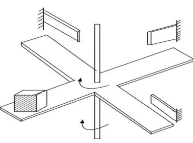
Figure 3.5 shows a simple sorting mechanism based on the size of the spherical object. In Figure 3.5 (a), a spherical object is allowed to roll over the rails with varying distance in between the two rails. When the object reaches a point where the gap between the rails is equal to the diameter of the object, it falls in the chamber placed below. Figure 3.5 (b) shows another mechanism with a trap door and gate. The spherical object pushes the gate based on its height. This helps to decide the path in which the object should travel. If the object does not touch the gate, it falls through the trap door. If it touches the gate, it moves forward along the other path as the trap door is closed. This mechanism is best suited for spherical objects. Objects can be sorted at a time into two categories using this method.
Figure 3.5: Simple sorting mechanisms [SC01]
Figure 3.6: Sorting by height mechanisms
Figure 3.7 shows four-bar-linkages mechanisms for sorting. Figure 3.7 (a) shows a mechanism where the parts are separated in a moving conveyor. This is similar to the oscillating and reciprocating mechanism seen earlier. Figure 3.7 (b) shows a mechanism to separate the group of cylindrical components using a hopper which tilts to separate the objects. Figure3.7 (c) shows a mechanism for separating cylindrical objects based on the gravity.
Figure 3.7: Simple separating mechanisms [SC01]
3.3 Summary
Chapter 4
Design and Analysis of Object Sorting and
Dispensing Models
In this chapter three different design models for the object sorting and dispensing are proposed. A comparison of the three models is done with the key features and parameters. A validation and analysis of the models are done based on the task variables. The best model is recommended for construction.
4.1 Models designed for object dispensing
The basic requirement for the design is that the system should be simple and feasible. The model should meet the specifications considered for design. The idea behind designing various models is to look for different ways to achieve the goal of better dispenser design. Both the positive and negative points of the designs are considered and evaluated. A model may seem to be simple but the components involved in them may be too costly. Similarly a model may seem to be more complex but the components can be relatively cost effective. There should be a right mix of the components and technical feasibility. In this paper three design models are proposed based on the technical feasibility and other approaches. They are:
1. Slider model;
Details of the three different design models are discussed in the following sections.
4.1.1 Slider Model
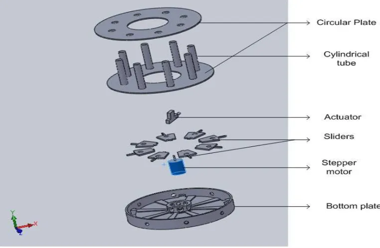
This design model is based on a slider mechanism, as shown in Figure 4.1. It contains a small slider which can accommodate the object that needs to be dispensed. We designed a casing for the tablets where the tablet can comfortably placed and the actuator can push the casing, which is called slider. A detail of the design is shown in Figure 4.1. The sliders are designed depending on the sizes and shapes of the objects. A slider is pushed by an actuator from its position and thus the objects falls. When the slider is pushed away by the actuator, it also blocks the movement of the other objects in the tube.
In this model an actuator and stepper motor are used as the main driving components. As shown in Figure 4.1, the slider is designed in such a way that it can hold a tablet in the small opening at its center. A push of the slider moves the tablet towards the other end when the actuator is powered. The slider slides in along the guides which prevents the slider from unwanted movement. A spring is installed at the end of the slider which is compressed when the actuator is powered and slider is pushed to move the tablet. This spring action can bring the slider back to its original position when the actuator is disconnected from power. A slider serves the following purposes:
1. The slider serves as a predetermined position where the tablet sits when it slides through the cylindrical tube.
2. The slider prevents any unexpected movement of other tablets in the cylindrical tube when actuator is pushing the current tablet.
3. The slider helps the actuator to push the tablet and comes back to the original position with the help of a spring action when the actuator is reversed.
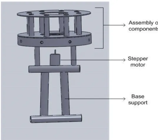
towards the required position. The actuator pushes the slider, moves the tablet from the cylinder and blocks the movement of other tablets in tube. The thickness of the slider should be equal to the thickness of the tablet so that by replacing the slider of different thickness, it can accommodate tablets of different thickness. The basic circular plate is connected to several cylindrical tubes as shown in Figure 4.2.
Figure 4.2: Slider model assembly
Figure 4.3: Slider model assembly
In this design model, the slider has opening equivalent to the size of the tablets (see Figure 4.1). The height of the slider is equivalent to the height of the tablet. Thus the slider can accommodate only one tablet at a time. When the actuator pushes the slider, it moves away from its resting position by compressing the spring. It also blocks the movement of any other tablets in the tube above. When the actuator is released, the spring enforces slider back to its original resting position. It also loads the next tablet from the cylindrical tube. The spring gets compressed when the actuator is activated. The assembled structure of the model design is shown in Figure 4.3.
4.1.2 Geneva mechanism model
with Geneva mechanism, the wheel contains a grove and rotation of the wheel can be controlled using a stepper motor. The engaging and disengaging of stepper motor with the wheel will be a tough task. The opening and closing of the wheel dispenses the object. If there is any problem in opening and closing at the right time, it results in the failure of dispensing the object.
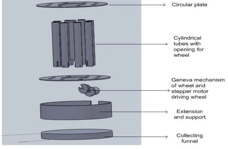
Figure 4.4 Geneva mechanism assembly with components
in Figure 4.5, a Geneva mechanism is used in the design. The Geneva mechanism helps to rotate the wheel without getting fixed to a stepper motor. However, the Geneva mechanism may cause the error of positioning the wheel away from the cylindrical tube. This may result in error while loading tablets. To exactly position the rotating Geneva mechanism is a real challenge. The wheel needs to be fixed and free from rotation, when it is not engaged with the Geneva wheel. This involves designing a special stopper to stop any unwanted movements. The rotational direction also needs to be streamlined for one direction. To stop the movement of wheel, it needs gears to hold a lever and control the movement. This makes the system more complex. When replacing a wheel, the lever also needs to be considered. This adds even more problems to the design. The exact engagement of wheels with Geneva wheel will become challenging when the circular base plate is rotating 360 degrees.
The engagement and disengagement of the wheels is shown the Figure 4.5. Due to the drawbacks of Geneva mechanism and the wheel alignment position problem, this model was not further considered in this paper.
Figure 4.5: Geneva wheel alignment
4.1.3 Gear-driven model
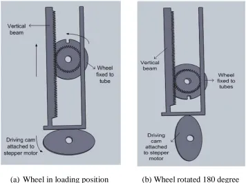
mentioned problems. The Geneva mechanism is replaced with gears as shown in Figure 4.6. The rack and pinion gear is used and the rack is attached to a stepper motor. The operation of the stepper motor controls the rack and it makes the wheel to rotate 180 degrees to drop the object, as shown in Figure 4.6.
As shown in Figure 4.6, the rack and pinion gear arrangement is considered as a replacement of the Geneva mechanism. The rack is connected to the stepper motor which makes it move. The wheel is attached with the pinion. The wheel is turned 180 degree by the rotation of the stepper motor through rack and pinion gear. When the rack moves away, the wheel is disengaged and thus the circular plate can be rotated using the other stepper motor. The working is explained in following three stages. In the first stage the stepper motor runs and pushes the rack towards the other end in order. This is shown in Figure 4.6.
Figure 4.6: Rack and pinion arrangement
Figure 4.7: Rack and pinion arrangement
In the third stage the rack completes its motion and the wheel has rotated 180 degrees. Thus the tablet falls down easily. This is shown in Figure 4.8.
Figure 4.8: Rack and pinion arrangement
moved and cam rotation is done using the stepper motor as usual. This system is better than the Geneva model as it has the gear which aims in the precise motion of the wheel. The model also arrests the wheel from the unwanted movement. The detailed diagrams of the stages are shown in Figure 4.9. The challenges with the third design model are the difficulty of manufacturing of the small gears, racks and pinion.
(a) Wheel in loading position (b) Wheel rotated 180 degree Figure 4.9: Gear driven model component
4.2 Analysis of the three dispenser models
Among the three different models, we plan to identify one best model and construct a working prototype. We need to decide which design is the most efficient, reliable and simple to construct.
4.2.1 Comparison of three models
features to be compared are the design and working mechanism. If the design is simple and has a good working mechanism it is given a high priority. Complex or difficult models are given lower score. The feasibility of working with different sizes of tablets is considered as a better design. The number of components required to assemble in the system is also considered. The model with fewer components is given a higher priority. Interchangeable parts are another key feature to be considered. If there is good inter replace ability then it needs less components to accommodate different tablet sizes. Based on these parameters the three models are compared and the comparison is shown in Table 4.1.
Table 4.1: Comparison of three models
1.2.1
Evaluation of models
Part merit rating is calculated for parts used in the assembly based on the individual components [Carl04]. Part merit is calculated with the feeding merit, insertion merit and fastening merit, as shown in Table 4.2. The merit is the numerical value from 0 to 10. Merit is assigned to each part for each of the three assembly events. Zero represents that the event being very difficult to accomplish and ten represents that it is very easy to complete. The part merit can be formulated as follows:
Model 1 Model 2 Model 3
Features Slider model Geneva mechanism
model
Gear driven model
Working mechanism Simple Moderate Complex
Feasibility of working with different size of tablet
Yes Yes Yes
Total number of components
39 36 28
Interchangeable of components
Yes Yes but not to a great
extent
Yes but not to a great extent
Gears No No Yes
Part Merit
= 𝐹𝑒𝑒𝑑𝑖𝑛𝑔 𝑚𝑒𝑟𝑖𝑡
2+ 𝐼𝑛𝑠𝑒𝑟𝑡𝑖𝑜𝑛 𝑚𝑒𝑟𝑖𝑡2+ 𝐹𝑎𝑠𝑡𝑒𝑛𝑖𝑛𝑔 𝑚𝑒𝑟𝑖𝑡2
3 (1)
Combined Average Merit (CAM)
=𝑆𝑢𝑚 𝑜𝑓 𝑝𝑎𝑟𝑡 𝑚𝑒𝑟𝑖𝑡𝑠
𝑆𝑢𝑚 𝑜𝑓 𝑝𝑎𝑟𝑡𝑠 (2)
Product Assembly Merit (PAM)
= 𝐶𝐴𝑀 1 −𝑆𝑢𝑚 𝑜𝑓 𝑟𝑒𝑑𝑢𝑛𝑑𝑎𝑛𝑡 𝑝𝑎𝑟𝑡𝑠
𝑆𝑢𝑚 𝑜𝑓 𝑝𝑎𝑟𝑡𝑠 (3)
From Equations (2) and (3), CAM and PAM ratings are used to evaluate the models finally. Table 4.2 shows the CAM and PAM rating of the slider mode. Table 4.3 shows the CAM and PAM rating of the Geneva mechanism model. Table 4.4 shows the CAM and PAM rating of the gear driven model.
Table 4.2: CAM and PAM rating of the slider model
Part Name No. Feeding Insertion Fastening
Part Merit
Redundant Part
Circular Plate 1 8 9 8 8.35 0
Circular Plate 1 8 9 8 8.35 0
Cylindrical tube 1 9 8 9 8.68 0
Cylindrical tube 1 9 8 9 8.68 0
Cylindrical tube 1 9 8 9 8.68 0
Cylindrical tube 1 9 8 9 8.68 0
Cylindrical tube 1 9 8 9 8.68 0
Cylindrical tube 1 9 8 9 8.68 0
Cylindrical tube 1 9 8 9 8.68 0
Table 4.2 Continued
Part Name No. Feeding Insertion Fastening
Part Merit
Redundant Part
Bottom Plate 1 8 9 7 8.04 0
Stepper motor 1 8 9 8 8.35 0
Actuator 1 8 9 8 8.35 0
Funnel 1 8 9 8 8.35 0
Size Converter 1 9 10 9 9.35 0
Size Converter 1 10 10 9 9.68 0
Size Converter 1 10 10 9 9.68 0
Size Converter 1 10 10 9 9.68 0
Size Converter 1 10 10 9 9.68 0
Size Converter 1 10 10 9 9.68 0
Size Converter 1 10 10 9 9.68 0
Size Converter 1 10 10 9 9.68 0
Slider 1 9 9 9 9.00 0
Slider 1 9 9 9 9.00 0
Slider 1 9 9 9 9.00 0
Slider 1 9 9 9 9.00 0
Slider 1 9 9 9 9.00 0
Slider 1 9 9 9 9.00 0
Slider 1 9 9 9 9.00 0
Slider 1 9 9 9 9.00 0
Spring 1 9 8 8 8.35 0
Spring 1 9 8 8 8.35 0
Spring 1 9 8 8 8.35 0
Spring 1 9 8 8 8.35 0
Spring 1 9 8 8 8.35 0
Spring 1 9 8 8 8.35 0
Spring 1 9 8 8 8.35 0
Spring 1 9 8 8 8.35 0
Base 1 10 8 9 9.04 0
Sum 39
CAM 8.82
Table 4.3: CAM and PAM rating of the Geneva mechanism model
Part Name No. Feeding Insertion Fastening
Part Merit
Redundant Part
Circular Plate 1 8 9 8 8.35 0
Circular Plate 1 8 9 8 8.35 0
Cylindrical Tube 1 9 8 9 8.68 0
Cylindrical Tube 1 9 8 9 8.68 0
Cylindrical Tube 1 9 8 9 8.68 0
Cylindrical Tube 1 9 8 9 8.68 0
Cylindrical Tube 1 9 8 9 8.68 0
Cylindrical Tube 1 9 8 9 8.68 0
Cylindrical Tube 1 9 8 9 8.68 0
Cylindrical Tube 1 9 8 9 8.68 0
Geneva Wheel 1 8 7 7 7.35 0
Wheel 1 7 6 7 6.68 0
Wheel 1 7 6 7 6.68 0
Wheel 1 7 6 7 6.68 0
Wheel 1 7 6 7 6.68 0
Wheel 1 7 6 7 6.68 0
Wheel 1 7 6 7 6.68 0
Wheel 1 7 6 7 6.68 0
Wheel 1 7 8 7 7.35 0
Fixing clamp for wheel 1 8 8 7 7.68 0
Fixing clamp for wheel 1 8 8 7 7.68 0
Fixing clamp for wheel 1 8 8 7 7.68 0
Fixing clamp for wheel 1 8 8 7 7.68 0
Fixing clamp for wheel 1 8 8 7 7.68 0
Fixing clamp for wheel 1 8 8 7 7.68 0
Fixing clamp for wheel 1 8 8 7 7.68 0
Fixing clamp for wheel 1 8 8 7 7.68 0
Stepper Motor 1 8 9 8 8.35 0
Size Converter 1 9 10 9 9.35 0
Size Converter 1 9 10 9 9.35 0
Size Converter 1 9 10 9 9.35 0
Size Converter 1 9 10 9 9.35 0
Table 4.3 Continued
Part Name No. Feeding Insertion Fastening
Part Merit
Redundant Part
Size Converter 1 9 10 9 9.35 0
Size Converter 1 9 10 9 9.35 0
Size Converter 1 9 10 9 9.35 0
Sum 36
CAM 8.12
PAM 8.12
Table 4.4: CAM and PAM rating of the gear driven model
Part Name No. Feeding Insertion Fastening
Part Merit
Redundant Part
Circular plate 1 8 9 8 8.35 0
Circular plate 1 8 9 8 8.35 0
Wheel with gear 1 6 7 7 6.68 0
Wheel with gear 1 6 7 7 6.68 0
Wheel with gear 1 6 7 7 6.68 0
Wheel with gear 1 6 7 7 6.68 0
Wheel with gear 1 6 7 7 6.68 0
Wheel with gear 1 6 7 7 6.68 0
Wheel with gear 1 6 7 7 6.68 0
Wheel with gear 1 6 7 7 6.68 0
Fixing clamp for wheel 1 8 8 7 7.68 0
Fixing clamp for wheel 1 8 8 7 7.68 0
Fixing clamp for wheel 1 8 8 7 7.68 0
Fixing clamp for wheel 1 8 8 7 7.68 0
Fixing clamp for wheel 1 8 8 7 7.68 0
Fixing clamp for wheel 1 8 8 7 7.68 0
Fixing clamp for wheel 1 8 8 7 7.68 0
Fixing clamp for wheel 1 8 8 7 7.68 0
Size Converter 1 9 9 9 9.00 0
Size Converter 1 9 9 9 9.00 0
Size Converter 1 9 9 9 9.00 0
Table 4.4 Continued
Part Name No. Feeding Insertion Fastening
Part Merit
Redundant Part
Size Converter 1 9 9 9 9.00 0
Size Converter 1 9 9 9 9.00 0
Size Converter 1 9 9 9 9.00 0
Size Converter 1 9 9 9 9.00 0
Stepper motor with gear 1 8 8 9 8.35 0
Rack 1 7 8 7 7.35 0
Sum 28
CAM 7.83
PAM 7.83
Table 4.5: Comparison of CAM and PAM rating for the three different models
Table 4.5 shows the overall CAM and PAM evaluation of all the three models. If the CAM and PAM ratings are the same, it indicates that the design is optimized with non-repetitive parts. A model is considered as a better design, if it has a higher CAM value.
Validation of the three models is also done based on the following features. The working feasibility is considered for 40%, components involved in the system constitute for 25%, interchangeability of components for 10%, efficiency and reliability of the system for 15%, and other parameter like manufacturing cost, construction, assembly of the components are considered for 10%. Based on these parameters the three models are compared and shown in Table 4.6. Figure 4.10 shows the pie chart percentage distribution of the features.
S.No Model Parts CAM PAM
1 Slider Model 39 8.82 8.82
2 Geneva Mechanism Model 36 8.12 8.12
Figure 4.10: Pie chart of parameters for validation
As shown in Figure 4.11, based on the validation, the first model with the slider is a better design than the other models. The problem with the Geneva mechanism model (the second model) is that the wheel component needs to be replaced and it requires the second stepper motor. In the third model with gears, the mechanism is simple but the manufacturing of the gears and the interchangeability are challenges. The slider model scores high because of the simple mechanism design of the actuator. The slider can also be easily replaced easily. The slider model is selected and considered as the best model design for prototype.
Table 4.6: Comparison of model based on the features and construction
Features Slider Model Geneva mechanism model Gear driven model
Design and working 38 30 35
Components 21 23 24
Inter replace ability 10 7 7
Efficiency and reliability 15 10 10
Other parameters 9 6 6
Total 93 76 82
40
25 10
15
10
Design and working
Components
Inter replaceability
Efficiency and reliability
Figure 4.11: Overall comparison of the models
4.3 Summary
In this chapter we presented three different design models for object sorting and dispensing. Comparisons of the different models are discussed. Based on the analysis, the model with the simplest feasible mechanism is selected. In the next chapters, details of constructing the selected slider mechanism and the development of the automated control system are discussed.
0 5 10 15 20 25 30 35 40 38 21 10 15 9 30 23
7 10 6
35
24
7 10 6 Slider Model
Geneva mechanism model
Chapter 5
Sorting and Dispensing System Design
5.1 Working mechanism of the slider model
The working mechanism of the slider model is shown in Figure 5.1. The slider rests on the bottom plate between the guides. The slider has a small opening at the center in which it can carry a tablet. The opening at the center is usually based on the shape of the tablet. If a tablet is hexagonal shaped, then the opening should be hexagonal to accommodate the tablet. If the tablet is round, then the opening can be a circular one. The circular opening at the center can also accommodate other shapes of tablets like square, rectangle and hexagon. The slider carries the tablet based on its size and the slider width need to be equal to the width of the tablet. As shown in Figure 5.1, the slider is pushed away from its position to release the tablet. The plate has slots which allow the tablet to fall on the gravity. When the slider is pushed the spring is compressed on one end of the slider, as shown in Figure 5.1. The length of the spring should be greater than or equal to the slider extension.
Ø
Ø
Actuator Stroke Length = 0.75'
Actuator
Actuator at full stroke length Slider
Spring
Figure 5.1: Mechanism of the slider
5.2 Design of components
The components used for the slider mechanism are listed in Table 5.1. The detailed design and description of all these components are discussed in the following sections
Table 5.1: List of components for the slider model
Components Required
numbers
Circular plate with 8 slots for cylindrical tube 2
Cylindrical tube 8
Bottom plate with guide to help slider
movement 1
Slider 8
Spring 8
Actuator 1
Stepper motor 1
Size converters 8
5.2.1 Circular plate
The circular plate serves the purpose of holding all the cylindrical tubes on which the tablets can be loaded. As shown in Figures 5.2 and 5.3, the circular plate has eight slots on which the cylindrical tubes can be inserted. We decided to go with eight slots for the whole 360 degrees, each slot is carved out at 45 degrees as shown in Figure 5.4. The number of degrees between the slots can be varied according to the number of slots and working angle. If the number of slots is increased to twelve, the angle between the slots will be 30 degrees.
As mentioned earlier the circular plate serves as the base on which the whole system is built. There are two circular plates used in this system. The cylindrical tubes are held in between these circular plates. A cylindrical tube contains the loaded tablets to be dispensed. The circular plate of radius 150 mm is designed, as shown in Figure 5.4. The slots for the cylindrical tube are located at 105 mm distance from the center. The radius of a slot is 20 mm. We provide an opening for the actuator to rotate at the center is 58 mm. The reason for opening at the center is to allow the free movement of the actuator. In the preliminary design, we had a base plate without an opening for the actuator. A shaft connects the center of the circular plate to a stepper motor to rotate in Geneva mechanism model. As the plates are kept stationary in this model there is no need to connect these plates to the stepper motor. The initial design of the cylindrical plate is shown in Figure 5.2. Figure 5.3 shows three dimensional view of the circular plate done using Solidworks. Figure 5.4 shows the drawing of the circular plate.
(a) Circular plate (b) Bottom plate
Figure 5.3: Circular Plate
Figure 5.4: Circular plate –drawing
5.2.2 Cylindrical tube
The cylindrical tube holds the tablets to be dispensed and it is also used to connect circular plates. The cylindrical tube with a length of 90 mm is selected. The cylindrical tube is made of plastic and it is transparent. Figure 5.5 shows the cylindrical tube.
Figure 5.5: Cylindrical tube
The transparent tube is helpful to view the tablet‟s orientation. To avoid the misalignment of tablets, the space available in the cylindrical tube should be slightly larger than the size of the tablet. The tube is a primary component in aligning the tablets in proper orientation to the slider. The diameter of tube should be exactly equal or slightly greater than the length of the tablet. The reason behind the clearance space is that it allows the tablet fall freely by gravity. To keep the tablets in good orientation, the cylindrical tube should be slightly greater than the tablet size. In some cases the tablet shape is different from round, in such cases the cylinder is housed with some liner which gives the exact size of the tablet. For example, the capsule has an elongated shape and the cylindrical tube may not hold it in its orientation. A liner should be used to modify the cylinder to exactly enclose the capsule in the proper orientation.
5.2.3 Bottom plate
Figure 5.7. The distance between these two slots should be exactly equal to the stroke length of the actuator. If the distance is less than the stroke length, it serves better for the purpose. If the distance is greater than the stroke length, the slider cannot reach the slot and dispense the tablet. The spring force pushes back the slider. The alignment should be in such a way that the opening in the slider should be in a straight line with the cylindrical tube. In order to align the slider back to its original position the stoppers and guide were designed. The guide is the space along which the slider can glide through.
Figure 5.6: Bottom plate
The guide is designed in such a way that it aligns slider in its position at the end of each cycle. The main purpose of the guide is to guide the slider. A three dimensional representation is shown in Figure 5.6. The bottom plate drawing is shown in Figure 5.7.
5.2.4 Slider
The slider is an important component which holds the tablets from the cylindrical tube and drops them to the collecting cup. The slider is the key component in the tablet dispenser. As shown in Figure 5.8, the slider varies in the thickness depending on the height of the tablet and the slot in which it carries the tablet. It also depends on the different shapes of the tablets. Three different types of slider designs are shown in Figure 5.8.
(a)Slider for circular (b) Slider for capsule. (c) Slider for small circular tablets. tablets.
Figure 5.8: Different types of sliders
The slider was initially designed for 45 degrees without any guides. Thus eight sliders will constitute for 360 degree. While testing with these sliders, these sliders did not function properly due to friction. Then the design was modified with guides. The slider angle was reduced to 25 degrees and the side guides was modified to 10 degrees each on both sides. The guides were joined together to form 20 degrees. The design of the slider was modified to have some extensions on outer side and inner side. The long pin was, designed for the holding the spring, as shown in Figure 5.9. The purpose of the spring is to retrieve the slider back to its original position. The other end tail is to assist in making contact with the actuator.
directly. The total length of the slider should not be greater than the space available in the circular plate. The total length includes the extensions on both sides of the slider. The detailed dimensions of the slider are shown in Figure 5.9.
Figure 5.9: Drawing of slider
5.2.5 Spring
position. Figure 5.10 shows the spring and slider.
Figure 5.10: Slider spring interface
The length of the spring is an important parameter to be considered. If the spring length is less than the slider extension, it results in a gap space on which the slider can freely move without any obstruction. This may cause poor performance of the system. The slot at the center of the slider should be greater than the length of the tablet. The shape of the slot should also correct in matching the shape of tablet to function properly. For example if the tablet is round, the slider slot should also be a round one. The rectangular slot does not serve well in this case.
The design and selection of the spring are specified as follows (also see Figure 5.11): Spring free length, Lfree = 1.5 cm
Spring length when deformed, Ldef = 0.4 cm Force exerted by spring, F = 39.22 N
The spring constant, K
= F
Figure 5.11: Spring specification details
Applying the values in Equation (4), the spring constant K can be calculated as follows:
K = 39.22
1.5−0.4
= 20.2 lbf / in = 3.55 x 10⁶dyne / cm
5.2.6 Actuator
Figure 5.12: Actuator used in the system.
Table 5.2: Actuator specifications
Specifications
Actuator base diameter 1” Full extension unit length 6-1/4” No extension unit length 5-1/2”
Dimensions 4”L x 2-1/4”W x 1-5/8”D
Weight 0.35 lbs
Lifecycle 100,000 times Temperature -40c to +80 c Push / pull load 4 Kg
Actuator lock/unlock time 0.2 seconds
Voltage 12+- 3
The car door actuator has a simple DC motor which runs a series of spur gears which serves as the gear reduction. The internal working gears are shown in Figure 5.13. The last gear drives a rack and pinion gear set that is connected to the rod. The rack converts the rotational motion of the motor into linear motion of the actuator. The gear system is shown in Figure 5.13.
5.2.7 Stepper motor
The stepper motor generates the desired angular movement for the actuator. In this system one actuator is used to serve the whole system. The actuator needs to rotate the full 360 degrees for movement. This is achieved using a stepper motor. A stepper motor can be used to achieve precise rotational motion. The stepper motor we used has 7.5 degrees per step. It takes 48 steps to cover the full 360 degrees movement. The rotation of the stepper motor can be controlled using computer program. The stepper motor used in this paper is shown in Figure 5.14.
Table 5.3: Stepper motor specifications
Specifications
AIRPAX Code 147878
Manufacturer Part Number 9904-112-31004 Angle per step 7.5DEG
SVHC No SVHC
Current Rating 175mA External Diameter 51mm External Length / Height 25mm Fixing Centers 60.2 mm Fixing Hole Diameter 3.5 mm Holding Torque 28 N-m
Indexing Angle 7
No. of Phases 4
Phase Resistance 65 ohm Power Consumption 3.8 W Shaft Diameter 3 mm Shaft Length – Metric 8.2 mm
Figure 5.14: Stepper Motor
As shown earlier in Figures 5.2 and 5.4, we decided to go for a circular plate with a diameter of 30 cm with a slot for 7.5 cm radius at the center to allow the space for actuator. The cylindrical tube contains tablets at distance 10.5 cm from the center. The eight cylindrical tubes are fixed in a circular pattern so that they are equidistant from the center of the circular plate and are accessible by actuator. The cylindrical tube slots are drilled with 1 cm radius which makes it serve for all types of tablets even allowing the maximum sized tablet. The size of the tube can be reduced using size converters to fit the slots.
5.2.8 Size converters
The size converters are the small circular shaped converters used to fix the cylindrical tubes of varying sizes to the circular plate. The size of the converter varies depending on the tablet sizes. The outer dimension is 20 mm, the same as the base diameter. The size converters are shown in Figure 5.15. The converters are made of acrylic sheet material of thickness of 3 mm. The size converters exactly fixes with the circular plate as it has the same dimension as the slot.
The size converters act like a washer to accommodate different tube sizes. Without the size converter, the cylindrical tubes of different shapes cannot be inserted into the hole at the circular plate. An example of cylindrical tube with the size converters is shown in Figure 5.16.
Figure 5.15: Different size converters
5.2.9 Funnel and base section
To collect the falling tablets from different tubes, a funnel is used. A funnel is placed below the bottom plate so that the falling tablets are collected and deposited in a collecting cup. A sheet metal is bent into a sliding surface and fixed to the base. The height of the system needs to be increased in order to make the sliding angle better for the funnel. The stepper is fixed with the wooden base to prevent its movement. The sheet metal funnel is fixed with the base. This directs all the tablets moving towards a single point collection where the collecting cup is placed. More detailed illustrations will be presented in Chapter 7.
5.3 Circuit and wiring for control
The circuit diagram of the electronic connection is shown in Figure 5.17. The connector is used to connect the PC gadget with the computer using its serial port used for connecting printer.
The PC gadget is also connected with the stepper motor and the actuator. The stepper motor is four phase and it has four connecting wires connected to pins 1 to 4 of PC gadget. The actuator has two wires. The actuator is connected to the pin 5 and 6. The stepper motor ground wires are connected to the ground pin available in the PC gadget.
The resistor is connected between the actuator and the PC gadget to adjust the voltage power supplied and to reduce the motor speed if needed. The normal response step time for the actuator is 0.2 seconds. The step time is very short. To increase the working time for the actuator, a resistor can be added. A resistor can control the time of actuator motion.
5.4 Summary
Chapter 6
Development of Programmable Control for
Automated Object Dispenser
In this chapter, the development of programmable control and software systems are discussed. Programmable logic controllers (PLCs) are the digital computers which control the automation and working of electromechanical components based on the inputs and sensor data. PLCs are most commonly used in industries for the purpose of automation. Computers can be used as the logic interpreter and decision maker based on the control algorithms. Details of the development of the programmable control for object dispensing are presented in the following section.
6.1 Hardware and software interface
Figure 6.1: Input and output pins testing control
Figure 6.1 shows the different input and output ports of the PC Gadget software application. The software interface of this system is shown in Figure 6.2. Figure 6.3 shows the structural outline of PC gadget. The hardware deals with the mechanism with stepper motor, actuator and the signal from the sensors. The software part is the Visual Basic code which takes the inputs from the user and generates the outputs. The system interface diagram is shown in Figure 6.4.
Figure 6.3: Structural outline
Figure 6.4: Hardware and software interface
The software program for this system was built using Visual Basic (VB) platform. The PC gadget is provided with a basic VB module for running a stepper motor and controlling input and output ports that have been configured to work with the printer port. In this case, there is a need to develop a software interface which can control the mechanisms. The basic module for testing the inputs ports, outputs ports and controlling stepper motor is given with the PC gadget. The Visual Basic application program needs to be developed for controlling stepper motor and actuator.
6.2 Design of the programmable control system
The basic purpose of the software is to get the input from the user. Given a prescription as input, the software actuates the dispensing system at a preconfigured time. The initial screen displays all the available tablets to be dispensed. The user can select the tablets which he/she wants to be dispensed. The time at which the tablet needs to be dispensed can also be configured. The user initially needs to load the tablets in the cylindrical tube and set the drug combination and dispensing timing via the user interface. For example, if a user is loading the tablet A in the cylindrical tube at position one, the user also specifies the timing when the tablet needs to be dispensed. When the position one is selected the system prompts asking for when the tablets should be dispensed. There are two kinds of cycles:
1. Regular schedule of morning, afternoon and night.
2. Interval schedule dispensing tablets at regular time intervals.
The user can select one of the two schedules. If the regular schedule is selected, then the interval schedule will be disabled. If the interval schedule is selected, the regular schedule will be disabled.
Once the routine schedule is selected it prompts the user to select the time period at which the system should dispense tablets. The patient can select at most three and at least any one of three. If the patient prefers interval routine i.e. the tablet needs to be dispensed at a regular interval, the user can select the interval period using the drop down box which list all possible intervals available.
Once the selection is done, the user can test the system using the test option. This will dispense the tablets scheduled for morning, afternoon and night routine once with proper message box and interval. This helps the patient to double check with the correctness of the input given to the system.
tablets does not exist it triggers the program to send an E-mail. This system is built with a touch sensor to detect the tablets dispensed. The settings button can be found in the initial screen. Clicking on this button leads to another screen where the morning, afternoon and night schedule time can be changed according to the user‟s convenience. Once the time is set and saved the window will close automatically and the details are saved.
6.2.1 User interface development
User friendly interface was developed for the dispensing system. It is developed by using Visual Basic based software application development platform. The Windows environment and the command buttons of Visual Basic makes it very easy for the user. The user gives inputs to the computer and the computer to follow the same. The check box, drop down and the command button are the three controls used in the system interface. The control flow and the logic sequences are programmed in the system to use the inputs given by the user and to generate the output based on these inputs. The input values entered are shown to the user as a message box where the user can check the corrections, the values was given.
6.2.2 Timer and interval algorithm
In this system, the program works in real-time. Once the system dispensing schedule is set, the timer in the Visual Basic starts running the code for every second (1,000 milliseconds). The counter increment includes, the hours, minutes and seconds based on the timer. When the set time is met, with the output is given to the stepper motor and the actuator are activated to dispense the medicine. There are interval schedules on which the tablets need to be dispensed for every one hour, two hours, etc. When the count reaches the exact time specified in the program, the stepper motor and the actuator are activated.
6.3 Control algorithm
called to activate the stepper motor and actuator control. The stepper motor has the accuracy of 7.57 degrees per step. The target position is calculated by the program and the stepper motor is used to turn the actuator to the target position.
Whenever the stepper motor is activated it moves and comes back to the home position number. The stepper motor can be moved in single step, double step and half step. In order to obtain a better resolution, the stepper motor uses a unit rotation step of 3.78 degrees. The values for the stepper motor positioning for different cylindrical tube numbers are shown in Table 6.1.
Table 6.1: Stepper motor position values in pulses
The pulses actuate the stepper motor and thus actuator reaches a cylindrical tube. Then the actuator pulse is given to push the slider and to dispense the tablet. When the actuator pulse is given as 0, actuator arm retracts and the slider moves back to its original position. The stepper motor rotation is a bidirectional one. The actuator wires connected to the PC gadget may get entangled when rotating in a single direction. The stepper motor rotates in the clockwise direction to reach a position. It then dispenses the tablet by actuator. Then it returns back to home position in counter-clockwise direction. A Boolean variable helps the program identify the direction of rotation.
Positions
Direction 1 2 3 4 5 6 7 8
Number of pulses for Clockwise
11.875 23.75 33.635 47.5 59.375 71.25 83.125 95 Number of
pulses for counter- clockwise
![Figure 2.1 Tablet dispensing and packaging [Kim03]](https://thumb-us.123doks.com/thumbv2/123dok_us/1762523.1226602/18.612.202.486.342.658/figure-tablet-dispensing-and-packaging-kim.webp)
![Figure 3.2: Feeding device mechanism [SC01]](https://thumb-us.123doks.com/thumbv2/123dok_us/1762523.1226602/26.612.149.490.115.226/figure-feeding-device-mechanism-sc.webp)