Technical Manual
Section 1
A
bout This Edition…
The release of the fifth edition of the ADIX Technical Manual contains new features, components,
enhancements, and programming classes and items that were included in Engineering Bulletins
circulated throughout the year. Below is a list of the new items added to the 5
thEdition ADIX
Technical Manual:
New!-
Features
! Alphanumeric Speed Dial by Name ! Voice Mail Monitor
! Call Logging
! Flexible Call Forward ! Group Monitoring
! Hunt Group Delayed Ringing ! ISDN Calling/Called Party Option ! Package/Version Displayed on Terminal
! Release Loop Operation on Analog E & M Tie Lines ! Station Based Recall, Camp-On, Forward Timer ! E-Response Help Call Feature
! Intercom Group Call Feature
! Relay Control from Single Line Telephones and Voice Mail Ports ! Automatic Relay Control
New!-
Components
! IX-MKT ! IX-HCIF ! IX-CTILINK ! IX-8SUBM-3 ! IX-8ESUBM ! IX-PMMSG
New!-
Enhancements
! Whisper Page Enhancements ! Network Enhancements ! Monitor Improvements
New!
- Database Programming Guide
Class 04
Class.Item Description Change Function
04.35<RLY1-32> Miscellaneous Function Port New Element Relay or sensor location 04.36 Miscellaneous Relay Timer New Element
04.37<RLY1-32> Miscellaneous Function New Element Relay Control
04.70<NUM36> Call Logging New Element Designates whether Caller ID/ANI/DNIS information is saved for All Calls or Abandoned Calls Only
04.70<NUM37> Network Switch Type New Element Designate the Network Switch Type 04.71<NUM 41> E-Response Help Call Time Out New Element Time in seconds
04.71<NUM 42> Automatic Relay Control Number New Element Relay Number 1-32 04.76<NUM 01> Automatic Relay Activation Time New Element Time of day HH:MM
04.77<NUM23> Voice Mail Packet Code New Element Voice Mail Stop Recording/Delete Message 04.79<NUM 08> E-Response Help Call LCD
Display
New Element ASCII characters.
Class 07
Class.Item <NUM> Description Range Default Note
07.06 43 SLT Relay Feature Access Number
null, 1-4 digits null Relay to control
Class 08
Class.Item <e1> <e2> Description Range Default Note 08.04 01-60 1-64 E-Response Help Call
Group Station/Zone 08.05 01-60 6 E-Response Help Call
Paging Group Setting
0-1 0 0=paging group
1=ICM Call Group
08.05 01-60 7 E-Response Group
Relay Number
0-32 0 Relay Number 1-32
Class 10
Class.Item Description Change Function
10.70 <EXTLxxx-4> Enable/Disable Group Monitoring New Element Designates whether the speaker is available when user presses [SPKR] at off-hook state 10.72<EXTLxxx- 7> Voice Mail Monitor New Element Enables extension to use the Voice Mail
Monitor Function
10.74<EXTLxxx-1> Station Hold Recall Timer New Item Designates the Hold Recall Timer for an individual station
10.74<EXTLxxx-2> Station Camp-On Recall Timer New Item Designates the Camp-On Recall Timer for an individual station
10.74<EXTLxxx-3> E-Response Help Call Extension New Item 0=Disable 1=Enable, Day Only 2=Enable, Day and Night 10.74<EXTLxxx-4> E-Response Help Call Group
Destination
New Item Group Number (1-60)
10.75<EXTLxxx-2> Station No Answer Call Forward Timer
Class 11
Class.Item Description Change Function
11.70<TRKLxxx-4> Trunk Packet (Centralized Voice Mail)
New Element Enable/Disable Extension Information
11.70<TRKLxxx-5> Extension Information (Centralized SMDR)
New Element Enable/Disable Trunk Packet
11.70<TRKLxxx-6> ISDN Numbering Option New Element ISDN Calling/Called Party Number Coding Option
11.73<TRKLxxx-3> Hunt Group as Delayed Call destination
New Element Set Hunt Group as the delayed call destination
Class 14.01/15.01
Class.Item Description Change Function
14/15.01 <NUM175>
I
ntroduction
Years of research and development have made the ADIX the most technologically advanced system ever designed by Iwatsu. This edition of the ADIX Technical Manual builds on the ADIX Technical Manual 4th Edition by adding new features and enhancements.
How to Use This Manual
This manual is designed to be the nexus between the technician and the ADIX. What you need to know, from installation to programming to troubleshooting is contained herein. Each of this manual’s six sections and the appendixare listed below followed by a brief description of its subject matter.
Section 1 −−−− Introduction • Overview of the ADIX Technical Manual, Fourth Edition.
Section 2 −−−− System Specifications • Listing of technical specifications.
Section 3 −−−− Features and Operations • A description of each system feature.
Section 4 −−−− Component Description • A description of each piece of system hardware.
Section 5 −−−− Installation Guide • Installation instructions and procedures.
Section 6 −−−− Database Programming Guide • A detailed description of the ADIX programming database.
Typographical Conventions
The typographical conventions used in this manual are listed below. They will help you quickly locate and identify specific information.
Formatting: Identifies:
!
PC bullet Important programming information. # pointer bullet Step-by-step instructions.boldface type Important instructions. Programming examples.
A reference to another section in the ADIX Technical Manual
italic type Specialized terms.
Variable information that must be dialed. A reference to a programming class/item [KEY] A specific button on the telephone.
Technical Manual
Section 2
Chapter 1
S
ystem Overview
The ADIX is a fully digital communications system that was designed to provide a multitude of voice and data communication features with the reliability that Iwatsu products are famous for. The system architecture of the ADIX is compliant with TAPI (Telephony Application Programming Interface) and TSAPI (Telephony Services Application Programming Interface) standards to allow for computer telephony integration (CTI).
System Architecture
The ADIX series is a stored program, distributed-control multi-microprocessor system that provides a wide variety of features and fast service. The main processor is either a high-speed 16-bit/12.5 MHz or 32-bit/25 MHz chip. Peripheral processing units (PPU) are also used for a number of features. The system supports an open architecture that is expandable to a maximum of 448 non-blocking ports.
The ADIX uses a digital control system based on time-division multiplexing and pulse-code modulation (PCM32) technology. Time-division multiplexing allows several low-speed transmission circuits to share a single high-speed channel by assigning each sub-channel exclusive use of the communications bank for a brief period or time slot. PCM32 is a technique in which an analog signal is converted to digital code. The amplitude of a voice conversation in the ADIX is sampled 8000 times per second, converted to digital code then transmitted and switched digitally. Together with the digital control system that optimizes the advantages of this switching system, the ADIX provides a universal port system that standardizes the unit interface thus simplifying system installation. Figure 2.1-1 illustrates the basic architecture of the ADIX universal port system.
Port
Interface
Modules
Highway
Additional
Power
Supplies
CPU
User
Devices or
Terminals
FIGURE 2.1-1 UNIVERSAL PORT SYSTEM
Central Processing Unit (CPU)
The central processing unit controls all the system functions through the ADIX operating system software and communicates to the outside world through the universal ports. For example, central office lines, system extensions.Highway Controller
The highway controller manages all the voice and data switching under control of the CPU.Port Interface Modules
These are the port interface cards which translate information such as voice energy and electric impulses into digital signals which communicate with the CPU and highway cards. Basic interface types are illustrated in figure 2.1-2.IX-8LGTK
IX-4EMTK
IX-4DITK
D C D C A or D C D C B
ADIX CO Line Connections
C P U P Highway
Loop Start Line Ground Start Line
E&M Tie Line
DID Line
IX-8PSUB
IX-8DSUB
IX-8SUBS-1
ADIX Station Connections
Highway Card
C P U Card
Attendant Consoles, KTs, DSS Units, Versa-Phones, Data Modules
ZT-D, ZT-S KT's
SLTs (on premises)
IX-8SUBM-1
IX-4SUBL
SLTs
(w/ message lamp)
SLTs (off premises)
IX-8CITK
Caller ID Line
FIGURE 2.1-2 BASIC CONNECTIONS
Chapter 2
S
ystem Specifications
Modular Design
The ADIX can be expanded to a maximum of 448 ports by adding expansion modules. The ADIX-M can be expanded to a maximum of 136 ports. The ADIX-S supports a maximum of 52 ports and easily migrates to an ADIX-M.
ADIX-S System and ADIX-M System Overview
IX-CMM-1 Common Module
! 5 Universal Card Slots
! Dimensions (HxWxD): 15.5"x19"x11.5" ! Weight: 26 lbs.
IX-EXPMM Expansion Module
! 2 Maximum
! 6 Universal Card Slots
! Dimensions (HxWxD): 11.5"x19"x11.5" ! Weight: 16 lbs.
IX-PWSS Power Supply
! Dimensions (HxWxD): 9.2"x2.7"x11" ! Weight: 4.3 lbs.
IX-PWSM Power Supply
! Dimensions (HxWxD): 9.2"x2.7"x11" ! Weight: 5.5 lbs.
ADIX-S
Switch Parameters
Time Division Multiplexed PCM32 Mu-law Speech Compression Time Slots:
IX-CPUP/HW:...512
Stored Program
Distributed Multi-microprocessor
System Memory
Component Flash Memory RAM
IX-CPUP/HW none 4 MB
IX-CPU20 MEM-M 4MB 0 MB
IX-CPU20 MEM-L 4MB 2MB
Heat Dissipation
IX-PWSS (maximum):...130 BTU/hr
IX-PWSM (maximum): ...162 BTU/hr
Environment
Operating Temperature: ...0° to 40°C/32° to 104°F
Storage Temperature:...-10° to 50°C/14° to 122°F
Relative Humidity
(non-condensing): ...10% to 90%
Seismic Withstanding
Applied Force Sweep Cycle/Wave Applied Waves Simulated Installation 0.25g vertical
0.125g horizontal
0.5-10Hz 30 Ground level, floor mount
0.5g vertical 0.25g horizontal
0.5-5Hz 30 2nd to 6th floor mount
Power
Nominal Maximum
IX-PWSS Input: 86 watts 122 watts
IX-PWSM Input: 167 watts 250 watts
AC Input
AC Input Voltage Tolerance:
IX-PWSS:...108V-132V @ 120V
IX-PWSM: ...90V-135V @ 110V
Frequency Tolerance:
IX-PWSS:...54 Hz-66 Hz
IX-PWSM: ...47 Hz-63 Hz
Ringing Generator
Frequency:...20 Hz
Amplitude: ...90 Vac
Maximum Simultaneous
Ringing (SLT): ...20
Battery Backup
ADIX-M (IX-PWSM) power supplies include a battery interface. Backup time is dependent upon battery array, system size and system usage. ADIX-S (IX-PWSS) power supplies do not include a battery interface.FCC Registration Numbers for ADIX-S and ADIX-M
KF: ...BD6MLA-21247-KF-E MF:...BD6MLA-21244-MF-E PF: ...D6MLA-21246-PF-EIC Registration Number
577 3326 AFacility Interface Codes
Loop Start Trunks: ... 02LS2 Ground Start Trunks:... 02GS2 DID Trunks:... 02RV2-T E&M Tie Lines: ... TL31M/TL32M OPS Lines: ... 0L13C T1-SF: ... 04DU9-BN T1-ESF:... 04DU9-1KN ISDN BRI: ... 02IS5 ISDN PRI: ... 04DU9-1KNSoftware Capacities
Outgoing Trunk Groups: ...60Incoming Trunk Groups: ...60
Incoming Call Ringing Assignment: 16 Stations/Line, 32 Stations/Line if delayed ringing assignment is not programmed. Incoming Call Delayed Ringing Assignment: ...16 Stations/Line Doorphone Ringing Assignment:...16 Stations/Doorphones Call Pick-up Groups:...60
CO/ICM Hunt Groups: ...60
Maximum Stations per Hunt Group:...32
Paging Groups Internal: ...30
Maximum Stations per Paging Group:...64
External Paging Zones: ...30
Station Speed Dial: ...10
System Speed Dial:...900
Maximum Digits per Speed Dial Number:...32
Speed Dial Alphanumeric ID: ...10 characters
CO/Station Alphanumeric ID:...8 characters
DID Alphanumeric ID: ...16 characters
Software Capacities (Cont.)
Forced Verified Account Codes: ...800
Park Orbits Attendant/System:...60
Station: ...1
Call Forwarding:...10 steps No Answer: ...no limit Programmable System Announcement Time: ...120 seconds (IX-CMSG) or 320 seconds (IX-CMSG-1) Flexible Numbering Plan: ...1-4 digits Station Text Messages: ...10
System Text Messages:...90
Text Message Groups:...60
Maximum Stations per Text Message Group: ...16
Circuits Per Card
Digital Station Card (IX-8PSUB):...8 Circuits Digital Station/Caller ID Trunk Card (IX-408): ...4 Caller ID Trunks and 8 Digital Station Circuits Digital Station/On-premise SLT Card (IX-044):...4 On-premise SLT and 4 Digital Station Circuits ZT-D Station Card (IX-8DSUB): ...8 circuits On-premise SLT Card (IX-8SUBS): ...8 circuits Off-premise SLT Card (IX-4SUBL): ...4 circuits MSG Lamp SLT Card (IX-8SUBM):...8 circuits Ground/Loop Start Trunk Card (IX-8LGTK): ...8 circuits Caller ID Trunk Card (IX-8CITK):...8 circuits Caller ID Trunk Module (IX-400):...4 circuits E & M Tie Line Trunk Card (IX-4EMTK): ...4 circuits DID Trunk Card (IX-4DITK): ...4 circuits T1 Trunk Card (IX-T1DTI):...1 circuit ISDN BRI Trunk Card (IX-2ICOTB) ...2 circuits ISDN PRI Trunk Card (IX-ICOTP): ...1 circuitAttendant Console (ADIX-M Only)
Maximum Attendant Positions: ...8Loop Keys (Incoming Lines):...8
Programmable Function Keys: ...16
Programmable DSS Keys:...30
Menu Driven Software Function Keys: ...8
Call Waiting Indications: ...12
Alphanumeric LCD:...4 rows, 40 characters
BLF Indications:...200 x 2
Telephone Requirements
Digital Telephones
Wiring:...1 pair
Total End-to-end Distance
Single Line Telephones
Wiring:...1 pair
Wiring w/Message Lamp: ...1 or 2 pair
Maximum Loop Resistance (Includes SLT)
On-premise SLT: ...600 ohm
Off-premise SLT: ...1,200 ohm
ADIX-S and ADIX-M Hardware Capacities Table
SYSTEM1 ADIX-S ADIX-M
Power Supply IX-PWSS IX-PWSM IX-PWSM IX-PWSM
Expansion Modules 0 0 1 2
Universal Card Slots 5 5 11 17
Number of Ports2 52 72 136 200
Trunk Ports3 28 32 80 128
Station Ports 32 32 80 120
Digital Station Ports 24 32 80 120
Attendant Positions 8 8 8 8
Attendant Consoles 0 8 8 8
BLF Units 0 8 8 8
DSS Units 8 8 8 8
On-premise SLTs 16 24 64 96
Off-premise SLTs 4 4 8 12
Doorphones 23 31 79 119
Busy Bypass Units4 12 16 40 60
Loop Start Trunks 16 32 80 128
Ground Start Trunks 16 32 80 128
E & M Tie Lines 4 16 40 64
DID Trunks 4 16 40 64
Message Cards (IX-MSGU) 3 3 6 8
IX-EDVIFCards5 1 1 1 1
Conference Circuits 8 8 8 8
T1 Cards3 1 1 3 5
ISDN BRI Cards3 3 3 6 9
ISDN PRI Cards3 1 1 3 5
1. This table lists the maximum quantity supported for each component type. The combined total number of ports for each system is limited to the “Number of Ports” category of this table. The capacities listed are based on the total number of card slots available, software restrictions and the power consumption of each component. It is recommended to use the ADIX Power Calculator Program to determine the exact power supply required.
2. The combined number of Station, Trunk, and Miscellaneous ports may not exceed the number of ports listed in this category.
3. The total number of trunks programmed may not exceed 160 for IX-CPU16M and 200 for IX-CPU32M. Based on configuration and usage, actual numbers may be less.
4. When Busy Bypass Units are used, the total number of Digital Stations may not exceed these numbers.
ADIX APS System Overview
IX-CML Common Module
! 5 Universal Card Slots
! Dimensions (HxWxD): 12.5"x19"x11.5" ! Weight: 17 lbs. Empty; 30.4 lbs. Full Capacity ! Power Supply: IX-PWSL, IX-PWSM, IX-PWSS
IX-EXPML1 Expansion Module
! 3 Maximum (2nd, 3rd, and 5th Shelf) ! 6 Universal Card Slots
! Dimensions (HxWxD): 11.5"x19"x11.5" ! Weight: 16 lbs. Empty; 29.7 Full Capacity ! Power Supply: IX-PWSL or IX-PWSM
IX-EXPML2 Expansion Module
! 1 Maximum (4th Shelf only) ! 6 Universal Card Slots
! Dimensions (HxWxD): 11.5"x19"x11.5" ! Weight: 16 lbs. Empty; 29.7 Full Capacity ! Power Supply: IX-PWSL or IX-PWSM
IX-PWSL Power Supply
! Dimensions (HxWxD): 10.5"x2.75"x11.5" ! Weight: 5 lbs.
IX-PWSM Power Supply
! Dimensions (HxWxD): 9.2"x2.7"x11" ! Weight: 5.5 lbs.
IX-PWSS Power Supply
! Dimensions (HxWxD): 9.2"x2.7"x11" ! Weight: 4.3 lbs.
System Architecture
Time Division Multiplexed PCM32 Mu-law Speech Compression Time Slots:
IX-CPUP/HW:...512
Stored Program
Distributed Multi-microprocessor
System Memory
Component Flash Memory RAM
IX-CPUP/HW none 4 MB
IX-CPU20 MEM-M 4MB 0 MB
IX-CPU20 MEM-L 4MB 2MB
Heat Dissipation
IX-PWSS (maximum):...130 BTU/hr
IX-PWSM (maximum): ...162 BTU/hr
IX-PWSL (maximum):...243 BTU/hr
Environment
Operating Temperature: ...0° to 40°C/32° to 104°F
Storage Temperature:...-10° to 50°C/14° to 122°F
Relative Humidity
(non-condensing): ...10% to 90%
Seismic Withstanding
Applied Force Sweep Cycle/Wave Applied Waves Simulated Installation
0.25g vertical 0.125g horizontal
0.5-10Hz 30 Ground level, floor mount
0.5g vertical
0.25g horizontal
0.5-5Hz 30 2nd to 6th floor mount
Power
Model Nominal Maximum
IX-PWSS Input: 86 watts 122 watts
IX-PWSM Input: 167 watts 250 watts
IX-PWSL Input: 252 watts 360 watts
AC Input
AC Input Voltage Tolerance:
IX-PWSS:...108V-132V @ 120V
IX-PWSM: ...90V-135V @ 110V
IX-PWSL: ...108V-132V @ 120V
Frequency Tolerance:
IX-PWSS:...54 Hz-66 Hz
IX-PWSM: ...47 Hz-63 Hz
IX-PWSL: ...47 Hz-63 Hz
Maximum Input Current IX-PWSS:...2.0A
IX-PWSM: ...2.0A
IX-PWSL: ...3.0A
Ringing Generator
Frequency:...20 Hz
Battery Backup
ADIX APS (IX-PWSL) power supplies include a battery interface. Backup time is dependent upon battery array, system size and system usage. See the table below to determine which power supplies allow a Battery Backup connection:
Power Supply
IX-PWSS No connection
IX-PWSM Battery Backup Connection IX-PWSL Battery Backup Connection
FCC Registration Numbers for ADIX APS
Key Telephone Systems:...BD6MLA-21247-KF-E
Multi-Function System(Hybrid): ...BD6MLA-21244-MF-E
PBX:...BD6MLA-21246-PF-E
IC Registration Number
577 3326 A
Facility Interface Codes
Software Capacities
Abandon Call Storage...500 call records
Account Codes:...12 digits
Call Forwarding:...10 steps
No Answer: ...no limit to steps
Call Pick-up Groups:...60
CO/ICM Hunt Groups: ...60
CO/Station Alphanumeric ID:...8 characters DID Alphanumeric ID: ...16 characters Doorphone Ringing Assignment:...16 stations/doorphones External Paging Zones: ...30
Flexible Numbering Plan: ...1-4 digits Forced Verified Account Codes: ...800
Incoming Call Delayed Ringing Assignment: ...16 stations/line Incoming Call Ringing Assignment: ...16 stations/line, 32 stations/line if delayed ringing assignment is not programmed. Incoming Trunk Groups: ...60
Maximum Digits per Speed Dial Number:...32
Maximum Stations per Hunt Group:...32
Maximum Stations per Paging Group:...64
Maximum Stations per Text Message Group: ...16
Outgoing Trunk Groups: ...60
Paging Groups Internal: ...30
Park Orbits Attendant/System: ...60
Station:...1
Programmable System Announcement Time: ...120 seconds (IX-CMSG), 320 seconds (IX-CMSG-1) Speed Dial Alphanumeric ID: ...10 characters Station Speed Dial: ...10
Station Text Messages: ...10
System Speed Dial:...900
System Text Messages:...90
Circuits Per Card
Caller ID Trunk Card (IX-8CITK):...8 circuits
Caller ID Trunk Module (IX-400):...4 circuits
Conference Card (IX-8CNFBOX-1):...8 circuits
DID Trunk Card (IX-4DITK): ...4 circuits
Digital Station Card (IX-16PSUB):...16 circuits
Digital Station Card (IX-8PSUB):...8 circuits
Digital Station/Caller ID Trunk Card (IX-408): ...12 circuits
Digital Station/On-premise SLT Card (IX-044):...8 circuits
E & M Tie Line Trunk Card (IX-4EMTK): ...4 circuits
Ground/Loop Start Trunk Card (IX-8LGTK): ...8 circuits
ISDN BRI Trunk Card (IX-2ICOTB) ...2 circuits
ISDN PRI Trunk Card (IX-ICOTP): ...1 circuit
MSG Lamp SLT Card (IX-8SUBM):...8 circuits
Off-premise SLT Card (IX-4SUBL): ...4 circuits
On-premise SLT Card (IX-8SUBS): ...8 circuits
T1 Trunk Card (IX-T1DTI):...1 circuit
ZT-D Station Card (IX-8DSUB): ...8 circuits
Attendant Console
Maximum Attendant Positions: ...8
Loop Keys (Incoming Lines):...8
Programmable Function Keys: ...16
Programmable DSS Keys:...30
Menu Driven Software Function Keys: ...8
Call Waiting Indications: ...12
Alphanumeric LCD:...4 rows, 40 characters
BLF Indications:...200 x 2
Telephone Requirements
Digital Telephones
Wiring:...1 pair
Total End-to-end Distance
22 AWG Twisted Pair: ...1,000 ft.
24 AWG Twisted Pair: ...1,000 ft.
1 Star Repeater:...1,500 ft.
2 Star Repeaters:...8,500 ft.
Single Line Telephones
Wiring:...1 pair
Wiring w/Message Lamp: ...1 or 2 pair
Maximum Loop Resistance (Includes SLT)
On-premise SLT: ...600 ohm
Off-premise SLT: ...1,200 ohm
ADIX APS System Capacity
1Type
Configuration IX-MEM-M IX-MEM-M IX-MEM-L IX-MEM-L IX-MEM-L
Shelf 5 IX-EXPML1
Shelf 4 IX-EXPML2 IX-EXPML2
Shelf 3 IX-EXPML1 IX-EXPML1 IX-EXPML1
Shelf 2 IX-EXPML1 IX-EXPML1 IX-EXPML1 IX-EXPML1
Shelf 1 1 IX-CML IX-CML IX-CML IX-CML IX-CML
IX-PWSL Power Supplies Required 1 2 3 4 5
Universal Card Slots 5 11 17 23 29
Number of Ports2 88 184 280 376 472
Trunk Ports3 36/52 84/116 132/180 180/200 200/200
Station Ports 72 144 216 288 360
Digital Station Ports4 72 144 216 288 360
Attendant Positions 8 8 8 8 8
Attendant Consoles 8 8 8 8 8
BLF Units 8 8 8 8 8
DSS Units 8 8 8 8 8
On-Premise SLTs 36 84 132 180 228
Off-Premise SLTs 4 8 12 16 20
Doorphones 71 143 215 287 359
Busy Bypass Units5 36 72 108 144 180
Loop Start Trunks 36 84 132 180 200
Caller ID Trunks 36 84 132 180 200
Ground Start Trunks 32 80 128 176 200
E & M Tie Trunks 16 40 64 88 112
DID Trunks 16 40 64 88 112
IX-MSGU Message Cards 3 7 8 8 8
IX-EDVIF Cards6 1 1 1 0 0
Conference Circuits 32 32 32 32 32
T1 Cards (IX-T1DTI) 2 4 6 8 8
ISDN BRI Cards (IX-2ICOTB) 4 10 16 22 28
ISDN PRI Cards (IX-ICOTP) 2 4 6 8 8
1. This table lists the maximum quantity supported for each component type based on the type of power supply installed on the shelf. The combined total number of ports for each system is limited to the “Number of Ports” category of this table. The capacities listed are based on the total number of card slots available, software restrictions and the power consumption of each component.
The combined number of Station, Trunk, and Misc ports may not exceed the number of ports listed in this category. 2. The maximum number of station ports per shelf may not exceed 72.
3. First number indicates the maximum trunk ports when IX-T1DTI or IX-ICOTP cards are not utilized. The second number indicates the maximum number of trunk ports when IX-T1DTI and IX-ICOTP cards are utilized. Based on configuration and usage, actual numbers may be less.
4. When Busy Bypass Units are used, the total number of Digital Stations may not exceed these numbers.
ADIX System Overview
IX-CM Common Module
! 12 Universal Card Slots
! Dimensions (HxWxD): 29.5"x20"x11.5" ! ADIX
! Weight: 73 lbs.
IX-EXPM Expansion Module
! 6 Maximum
! 8 Universal Card Slots
! Dimensions (HxWxD): 12"x20"x11.5" ! Weight: 35 lbs.
IX-100PWS Power Supply
! Dimensions (HxWxD): 6"x20"x11.5" ! Weight: 22 lbs.
IX-200PWS Power Supply
! Dimensions (HxWxD): 12"x20"x11.5" ! Weight: 48.5 lbs.
IX-BATBOX Battery Cabinet
! Dimensions (HxWxD): 17"x21.5"x12" ! Weight: 35 lbs.
IX-20PBOX Power Supply Cabinet
! Dimensions (HxWxD): 17"x21.5"x12" ! Weight: 33 lbs.
Switch Parameters
Time Division Multiplexed PCM32 Mu-law Speech Compression Time Slots:
IX-CPUP/HW:...512
Stored Program
Distributed Multi-microprocessor
System Memory
Component Flash Memory RAM
IX-CPUP/HW none 4 MB
IX-CPU20 MEM-M 4MB 0 MB
IX-CPU20 MEM-L 4MB 2MB
Heat Dissipation
IX-100PWS (maximum): ...1330 BTU/hr
Environment
Operating Temperature: ...0° to 40°C/32° to 104°F
Storage Temperature:...-10° to 50°C/14° to 122°F
Relative Humidity
(non-condensing): ...10% to 90%
Seismic Withstanding
Applied Force Sweep Cycle/Wave Applied Waves Simulated Installation 0.25g vertical
0.125g horizontal
0.5-10Hz 30 Ground level, floor mount
0.5g vertical 0.25g horizontal
0.5-5Hz 30 2nd to 6th floor mount
Power
Nominal Maximum
IX-100PWS Input: 425 watts 1300 watts
IX-200PWS: 800 watts 1700 watts
AC Input
AC Input Voltage Tolerance: ...90V-135V @ 110V
Frequency Tolerance:...47 Hz-63 Hz
Maximum Input Current
IX-100PWS: ...12A
IX-200PWS: ...16A
Ringing Generator
Frequency:...20 Hz
Amplitude: ...90 Vac
Maximum Simultaneous Ringing (SLT): ...20
Battery Backup
All power supplies include a battery interface. Backup time is dependent upon battery array, system size and system usage.
FCC Registration Numbers
KF: ...BD620Q-60444-KF-E
MF:...BD620Q-60087-MF-E
PF: ...BD6JPN-74017-PF-E
IC Registration Number
Facility Interface Codes
Loop Start Trunks: ...02LS2
Ground Start Trunks:...02GS2
DID Trunks:...02RV2-T
E&M Tie Lines: ...TL31M/TL32M
OPS Lines: ...0L13C
T1-SF: ...04DU9-BN
T1-ESF:...04DU9-1KN
ISDN BRI: ...02IS5
ISDN PRI: ...04DU9-1KN
Software
Outgoing Trunk Groups: ...60
Incoming Trunk Groups: ...60
Incoming Call Ringing Assignment: ...16 Stations/Line, 32 Stations/Line if delayed ringing assignment is not programmed.
Incoming Call Delayed Ringing Assignment: ...16 Stations/Line
Doorphone Ringing Assignment:...16 Stations/Doorphones
Call Pick-up Groups:...60
CO/ICM Hunt Groups: ...60
Maximum Stations per Hunt Group:...32
Paging Groups Internal: ...30
Maximum Stations per Paging Group:...64
External Paging Zones: ...30
Station Speed Dial: ...10
System Speed Dial:...900
Maximum Digits per Speed Dial Number:...32
Speed Dial Alphanumeric ID: ...10 characters
CO/Station Alphanumeric ID:...8 characters
DID Alphanumeric ID: ...16 characters
Account Codes:...12 digits
Forced Verified Account Codes: ...800
Park Orbits
Attendant/System: ...60
Station:...1
Call Forwarding:...10 steps
No Answer: ...no limit
Programmable System Announcement Time: ...120 or 450 seconds
Flexible Station Numbering Plan:...1-4 digits
Station Text Messages: ...10
System Text Messages:...90
Text Message Groups:...60
Circuits Per Card
Digital Station Card (IX-8PSUB):...8 Circuits
ZT-D Station Card (IX-8DSUB): ...8 circuits
On-premise SLT Card (IX-8SUBS): ...8 circuits
Off-premise SLT Card (IX-4SUBL): ...4 circuits
MSG Lamp SLT Card (IX-8SUBM):...8 circuits
Ground/Loop Start Trunk Card (IX-8LGTK): ...8 circuits
Caller ID Trunk Card (IX-8CITK):...8 circuits
Circuits Per Card (Cont.)
Caller ID Trunk Module (IX-400):...4 circuits
E & M Tie Line Trunk Card (IX-4EMTK): ...4 circuits
DID Trunk Card (IX-4DITK): ...4 circuits
T1 Trunk Card (IX-T1DTI):...1 circuit
ISDN BRI Trunk Card (IX-2ICOTB) ...2 circuits
ISDN PRI Trunk Card (IX-ICOTP): ...1 circuit
Attendant Console
Maximum Attendant Positions: ...8
Loop Keys (Incoming Lines):...8
Programmable Function Keys: ...16
Programmable DSS Keys:...30
Menu Driven Software Function Keys: ...8
Call Waiting Indications: ...12
Alphanumeric LCD:...4 rows, 40 characters
BLF Indications:...200 x 2
Telephone Requirements
Wiring:...1 pair
Total End-to-end Distance
22 AWG Twisted Pair: ...1,000 ft.
24 AWG Twisted Pair: ...1,000 ft.
1 Star Repeater:...1,500 ft.
2 Star Repeaters:...8,000 ft.
Single Line Telephones
Wiring:...1 pair
Wiring w/Message Lamp: ...1 or 2 pair
Maximum Loop Resistance (Includes SLT)
On-premise SLT: ...600 ohm
Off-premise SLT: ...1,200 ohm
ADIX Hardware Capacities
POWER SUPPLY1 IX-100PWS IX-200PWS
Expansion Modules 0 1 2 6
Universal Card Slots 12 20 28 56
Number of Ports2 96 160 224 448
Trunk Ports3 88 152 160 200
Station Ports 88 152 200 400
Digital Station Ports 88 152 200 400
Attendant Positions 8 8 8 8
Attendant Consoles 8 8 8 8
BLF Units 8 8 8 8
DSS Units 8 8 8 8
On-premise SLTs 80 144 192 392
Off-premise SLTs 40 72 104 216
Doorphones 87 151 199 399
Busy Bypass Units4 44 76 100 200
Caller ID Trunks 88 152 160 200
Loop Start Trunks 88 152 160 200
Ground Start Trunks 88 152 160 200
E & M Tie Lines 44 76 108 200
DID Trunks 44 76 108 200
Message Cards (IX-MSGU) 7 8 8 8
Misc. Cards (IX-MISC/IX-EDTCU) 2 3 4 7
Serial Cards (IX-SCIF, IX-HCIF) 3 3 3 3
IX-EDVIF Cards 1 1 1 1
Conference Circuits5 24 24 24 24
T1 Cards3 3 5 7 9
ISDN BRI Cards3 11 19 27 49
ISDN PRI Cards3 3 5 7 9
1. This table lists the maximum quantity supported for each component type. The combined total number of ports for each system is limited to the “Number of Ports” category of this table. The capacities listed are based on the total number of card slots available, software restrictions and the power consumption of each component. It is recommended to use the ADIX Power Calculator Program to determine the exact power supply required.
2. The combined number of Station, Trunk, and Miscellaneous ports may not exceed the number of ports listed in this category.
3. The total number of trunks programmed may not exceed 160 for IX-CPU16M and 200 for IX-CPU32-1. Based on configuration and usage, actual numbers may be less.
4. When Busy Bypass Units are used, the total number of Digital Stations may not exceed these numbers.
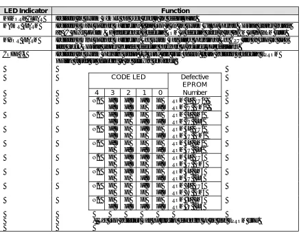
Key Telephone Lamp Indications
Status Lamp Indication
In Use (Green) Modulation Steady (On)
CO Incoming/Call Forward 0.1 sec. on, 0.9 sec. off
On Hold (Green) 0.5 sec. on, 0.5 sec. modulated on
System Hold/Non-Privacy 0.1 sec. off, 0.3 sec. modulated on Recall, ICM Incoming, MSG 0.7 sec. off, 0.3 sec. modulated on
DND 0.5 sec. on, 0.5 sec. modulated on
Busy Steady (On)
Station Port Requirements
Model Description Ports Required
IX-ATT Attendant Console 2
IX-BLF Busy Lamp Field 1
IX-DCKT900 Digital Wireless Telephone 1 or shared with
digital telephone
IX-DSS-A 50 DSS & 20 function keys with display 1
IX-DSS-A-2 50 DSS & 20 function keys with display 1
IX-DSS-B 50 DSS keys 1
IX-8KTS 8 line keys 1
IX-8KTD 8 line keys with display 1
IX-12KTS-2 12 line keys (24 line keys with IX-ELK) 1
IX-12KTD-2 12 line keys (24 line keys with IX-ELK) 1
IX-24KTS 24 line keys 1
IX-24KTD 24 line keys with display 1
IX-VT Versa-Phone 1
IX-DMS Data Module 1
IX-DDPH Digital Doorphone 1
Time Parameters
Hold Recall Timer...0 - 255 seconds
Timed Trunk Queuing...1 - 20 minutes
Doorphone Answer Time...5 - 255 seconds
VSS Recording Time...0 - 120 seconds
Hunting Time ...0 - 255 seconds
Night Mode Start Time ...00:00 - 23:59
Auto CO Answer Start Time ...00:00 - 23:59
MISC Relay Timer...10 - 255 ms
ADIX Signal Characteristics
CO Dial Tone
Condition: ... When making an outgoing call through Optimized Routing
Frequency: ... 352/432 Hz
Duration: ... Continuous
Repetition:... Continuous
Pattern:
ICM Dial Tone
Condition: ... When a station goes off-hook
Frequency: ... 432 Hz
Duration: ... Continuous
Repetition:... Continuous
Pattern:
ICM Dial Tone (2nd)
Condition: ... When a CO call is placed on a consultation hold (during transfer operation)
Frequency: ... 432 Hz
Duration: ... 0.2 second on/0.2 second off
Repetition:... Continuous
Pattern:
0.2s 0.2s 0.2s 0.2s 0.2s 0.2s 0.2s 0.2s 0.2s 0.2s
ICM Ringback Tone
Condition: ... When the called station is tone ringing Frequency: ... 432/480 Hz
Duration: ... 1 second on/3 seconds off
Repetition:... Continuous
Pattern:
1s 3s 1s
ICM Voice Call Tone
Condition: ... When the called station is voice called Frequency: ... 432 Hz
Duration: ... 1 second on
Repetition:... 1 burst
Pattern:
ICM Busy Bypass Tone
Condition: ... When the called station is busy but voice calledthrough the busy bypass module
Frequency: ... 800 Hz
Duration: ... 0.4 second on/0.2 second off
Repetition:... 2 bursts
Pattern:
0.4s 0.2s 0.4s
ICM Busy Tone
Condition: ... When the called station is busy Frequency: ... 480/624 Hz
Duration: ... 0.5 second on/0.5 second off
Repetition:... Continuous
Pattern:
0.5s 0.5s 0.5s 0.5s 0.5s 0.5s 0.5s 0.5s 0.5s 0.5s
ICM Busy Ringback Tone
Condition: ... When station busy override occurs
Frequency: ... 432/480 Hz
Duration: ... 0.5 second on/0.5 second off
Repetition:... Continuous
Pattern:
0.5s 0.5s 0.5s 0.5s 0.5s 0.5s 0.5s 0.5s 0.5s 0.5s
ICM Absence Tone
Condition: ... When the called station has left an absence message
Frequency: ... 432 Hz
Duration: ... 0.5 second on/0.5 second off
Repetition:... Continuous
Pattern:
0.5s 0.5s 0.5s 0.5s 0.5s 0.5s 0.5s 0.5s 0.5s 0.5s
ICM DND Tone
Condition: ... When the called station is in the "DND" mode
Frequency: ... 432 Hz
Duration: ... 0.1 second on/0.1 second off
Repetition:... 5 bursts, intermittent with 1.1 seconds of silence
ICM Warning Tone
Condition: ... When a non-existing station number is dialed
Frequency: ... 480/624 Hz
Duration: ... 0.2 second on/0.2 second off
Repetition:... 5 bursts, intermittent with 1.1 seconds of silence
Pattern:
0.2s 0.2s 0.2s 0.2s 0.2s 0.2s 0.2s 0.2s 0.2s 0.2s
Confirmation Tone
Condition: ... When feature access is acknowledged
Frequency: ... 432 Hz
Duration: ... 0.2 second on/0.2 second off
Repetition:... 3 bursts
Pattern:
0.2s 0.2s 0.2s 0.2s 0.2s
ICM Howler Tone
Condition: ... When the receiver remains off-hook over a preprogrammed time without completion of call processing
Frequency: ... 1532 Hz
Duration: ... Continuous
Repetition:... Continuous
Pattern:
CO Incoming Call
Condition: ... When an Incoming CO call rings
Duration: ... 1 second on/3 seconds off
Repetition:... Continuous
Pattern:
1s 3s 1s
CO Incoming Call (Caller ID/ANI/DNIS Trunk)
Condition: ... When an incoming CO call from a caller ID/ANI/DNIS trunk is received
Duration: ... 1 second on/3 seconds off (with caller ID/ANI/DNIS data on LCD)
Repetition:... Continuous
CO Camp-On Call
Condition: ... When another station camps on a CO line call
Duration: ... 1 second on/3 seconds off
Repetition:... Continuous
Pattern:
1s 3s 1s
CO Callback
Condition: ... When a queue for a CO line access calls back
Duration: ... 1 second on/3 seconds off
Repetition:... Continuous
Pattern:
1s 3s 1s
CO Consultation Hold Recall
Condition: ... When a consultation hold (by hook-flash) times out
Duration: ... 0.2 second on/0.2 second off
Repetition:... 3 rings with 3 seconds of silence
Pattern:
0.2s 0.2s 0.2s 0.2s 0.2s 3s
CO Camp-On Recall/Call Coverage Button
Condition: ... When a consultation hold of a CO call times out. When a call coverage button rings
Duration: ... 0.2 second on/0.2 second off
Repetition:... 3 rings with 3 seconds of silence
Pattern:
0.2s 0.2s 0.2s 0.2s 0.2s 3s
ICM Station-to-Station Call
Condition: ... When a station calls another station
Duration: ... 0.4 second on/0.2 second off
Repetition:... 2 rings with 3 seconds of silence
Pattern:
0.4s 0.2s 0.4s 3s
ICM Camp-On Call
Condition: ... When an ICM call is camped on
Duration: ... 0.4 second on/0.2 second off
Repetition:... 2 rings with 3 seconds of silence
ICM Callback
Condition: ... When a queued ICM call rings back
Duration: ... 0.4 second on/0.2 second off
Repetition:... 2 rings with 3 seconds of silence
Pattern:
Chapter 3
S
oftware Release & Hardware
Introduction History
July 1989 Version 1.0 Introduction October 1994 ADIX-M Introduced
February 1990 Version 3.0 Released CPU16M and EDVIF Cards Introduced
Multiple Trunk Group Access January 1995 Version 4.50/5.50 Released
Connect Key on KT Enhanced for new NANP compatibility
Headset Connection - KT DID & DISA Ringing to UCD Group
Remote CO FWD - External Control Attendant Paging Override Restriction
Remote CO Forwarding - Activation Attendant Release Key
Incoming CO Access Restriction Busy Camp-On from SLT
Flexible Outgoing Call Restriction Simplified DISA Short-Cut Operation
Busy Override Station Programming Two-Way DID on T1 trunks
Hotel/Motel Indication Control January 1995 ACD Version 2.10 Released
UCD Interval/Disconnect Timer Help Call
Programmable ATT Recall Destination Emergency Recording/Help
DIL Ringing Stations (up to 32) ACD Supervisors
Auto Outgoing CO - Station SPD 99 Dual-Group Log In
Call Pickup, Type of Calls Programming ACD/PBX Trunk-to-Trunk Conference
SMDR Min. Call Duration Unit min./sec. Call Sequence Key
June 1990 Version 4.0 Released Forced Qualification Code
Voice Mail Integration Speed Dial Forward from Call Sequence
Call Coverage Table
Fixed Call Forwarding November 1995 Version 4.61/5.61 Released
UCD Caller ID
True Attendant Position Automatic Number Identification (ANI)
Call Forward - Busy/No Answer Dialed Number Identification Service
IX-CPUL-1, IX-EMEM-1 introduced (DNIS)
April 1991 IX-CPU32, IX-ROMP32 Introduced November 1995 ACD Version 2.21 Released
October 1991 Version 4.2 Released Caller ID
T1 Interface Automatic Number Identification (ANI)
Forced Verified Account Code Dialed Number Identification Service
DID/DNIS Alphanumeric ID (DNIS)
UCD Enhancements June 1996 Version 4.62/5.62 Released
Transfer ability to UCD group Enhanced Caller ID, ANI, DNIS Name
Different 1st/2nd Msg. per UCD Group and Number Display
Voice Mail Integration Enhancements Private and Out-of-Area Routing for
Call-Out Function Caller ID Calls
Packet Table Expansion DID Number External Call Forward
No Double Packet Multiple Ringing Stations for DID, ANI,
AA/VM Combination Mode DNIS, and Caller ID
ZT-D X-Telephone Compatibility IX-PMSLINK Property Management
Expansion of Network Tables SLT Termination Signal (disconnect) UCD Enhancement (time parameter)
December 1996 Version 4.71/5.71 Released June 1999 Controller Card Modification
Abandoned Call Storage September 1999 IX-HCIF and IX-CTILINK introduced
Voice Mail Integration Enhancements November 1999 ADIX Version 6.20
Improved VM/AA Packet Descriptions Alphanumeric Speed Dial by Name
Text Messaging Voice Mail Monitor
Eight Personal Ringing Tones Call Logging
Flexible Key Assignment for Flexible Call Forward
IX-DCKT900 Group Monitoring
ISDN BRI Interface Hunt Group Delayed Ringing
ISDN PRI Interface ISDN Calling/Called Party Number
Call Recording Coding Option
January 1997 ADIX-S Introduced ISDN Trunk Feature Enhancement
June 1997 4.75/5.73/ACD 2.31 Released Monitor Improvements
Caller ID, ANI, DNIS Name and Number Package/Version Display on
Display Enhancements Programming Terminal
(5.73/ ACD 2.31 only) Release Loop Operation on Analog
ISDN PRI Support (IX-ICOTP) E&M Tie Lines
April 1998 Omega-Voice VMI Card Introduced Station Based Recall, Camp-On
May 1998 IX-CPUP/HW with IX-CPU20/MEM-X Forward Timer
Introduced Whisper Page Enhancements
May 1998 ADIX Version 6.00/ ACD Version 6.00 December 1999 Iwatsu Utility CD Released
Released March 2000 ADIX Software Version 6.30
Enhanced Networking E-Response Help Call Feature
Enhanced ISDN PRI Line Feature Intercom Group Call Feature
Whisper Page Relay Control from SLT and VM Ports
Transfer to Guest Mailbox Automatic Relay Control
One Touch Optimized Key IX-MKT Key Assignment
Technical Manual
Section 3
Chapter 1
S
ystem -Wide Features
911 Support
At default, ADIX is programmed to automatically contact your local Public Safety Answering Point (PSAP) when 911 is dialed. In addition, ADIX is one of the only ysytem that supports Enhanced 911 Service. Enhanced 911 Service ensures that when 911 is dialed from a system extension, information that allows the PSAP to identify the caller’s location in a building is sent to the PSAP along with the call. Check with your system installer or Authorized Iwatsu Distributor to make sure your system is programmed for Enhanced 911 Service.
Operation
1. From an outside or inside line:
1. Go off-hook. 2. Dial 911
You will be connected to your local Public Safety Answering Point (PSAP).
Abandon Call Storage
When a call on a Caller ID (IX-8CITK) or ANI (IX-T1DTI) line is disconnected before being answered, during transfer, or while on hold, system memory may retain caller information. This information includes the caller’s telephone number and name, date and time of the call, trunk number, and
destination station. This information can be output as a system event code or to SMDR. A maximum of 500 abandoned call records may be stored in memory.
The following types of incoming calls on Caller ID or ANI lines are considered abandoned calls:
! Caller hangs up or is disconnected before the call is answered.
! Caller hangs up or is disconnected while on hold or during hold recall. ! Caller hangs up or is disconnected during camp-on transfer or camp-on recall.
Keys Used for Abandoned Call Storage
Three keys, [USATn], [USAT], and [USAS], have been added to provide access for the abandoned call information that has been saved in the system memory. The [USATn], [USAT], and [USAS] keys are programmed in Class 14.01 or 15.01 to the desired key pattern. Use Class 10.12 to assign a key pattern to a specific station. The function of each new key is explained below:
Abandoned Call System Key [USAT].
The [USAT] key (Class 14.01/15.01 d1=166) may be used to check abandoned calls on any trunk group in the system. This key allows the user to select a specific trunk group to check for abandoned call records (the trunk group is based on Class 11.39). This key does not provide a lamp indication.Abandoned Call Trunk Group Key
[USATn].
The [USATn] key (Class 14.01/15.01 d1=167, d2=trunk group number 01-60 programmed in Class 11.39) is used to check abandoned calls received on a specific trunk group This key lights solid red to indicate abandoned calls were received on the associated trunk group.
Abandoned Call Station Key
[USAS].
The [USAS] key (Class 14.01/15.01 d1=168) is used to check abandoned calls received at an individual station. This key lights solid red to indicate information about a Caller ID/ANI call that was abandoned while ringing at a specific station or group of stations has been saved in system memory. The tables below list the relationship between the type of abandoned call and the stations at which the [USAS] key lamp will light.
Incoming Call Abandoned During Ringing
Type of Call Status When Disconnected Station(s) Receiving
Indication on [USAS] Key Lamp
Individual Station Call Station is ringing Ringing station
Incoming Call to a Hunt Group Ringing following hunting sequence programmed for the group
Station ringing when the call was abandoned
Caller ID/ANI call with Multiple Stations Ringing
Ringing at multiple stations All ringing stations
Recall Station is ringing with recall Station receiving recall
Attendant Intercept Attendant station(s) ringing Attendant station with lowest logical
port number
Call Abandoned After Answer by the System or a Station
Type of Call Status When Disconnected Station(s) Receiving
Indication on [USAS] Key Lamp
UCD Station Ringing Ringing station
Auto Attendant or Voice Mail Transfer to a Hunt Group
Ringing following hunting sequence programmed for group
Station ringing when the call was abandoned
Auto Attendant or Voice Mail Transfer (Camp-On)
Camped-on station is ringing Station ringing when the call was abandoned
Forwarding, Camp-on or Recall of a Call in Progress
Ringing at a station Station ringing when the call was
abandoned
Call in Progress on Hold Call on hold Station at which the call was placed on
Displaying Abandoned Call Information
When the [USATn], [USAT], or [USAS] key is pressed, the following information about the call is displayed on the station LCD:
FIGURE 3.1-1 ABANDONED CALL LCD DISPLAY
Station users can view the next saved abandoned call information by pressing [#] and the previous abandoned call record by pressing [∗].
Returning a Call Using the Stored Abandon Call Information
When a station user is displaying an abandoned call record, an outgoing call to the displayed number may be automatically initiated by pressing [FLT], [FLTn], or [COLn]. If optimized routing is programmed, a callout to the abandoned number can also be made by pressing the [USAT], [USATn], or [USAS] key a second time. Before initiating an outgoing call, up to four digits may be added to the abandoned call number. These additional digits, however, do not appear on the display during input, but do appear during call origination.
Note: In certain areas, local calls are received with ten Caller ID digits that include the area code. If the telephone company does not support local calls dialed with an area code, optimized routing must be used and correctly programmed to automatically remove the three-digit area code from the outgoing number.
Deleting Abandon Call Information
Abandoned call information can be deleted from memory either manually or automatically by the system.
Manual Deletion: Stations that have been assigned a [UAD] key can delete abandoned call information saved in system memory, one call at a time. When an abandoned call message is displayed, pressing the [UAD] key deletes the record from system memory. If an abandoned call record is accessible at more than one station via either the [USAS], [USATn] or [USAT] key, deleting the record from one station in effect deletes the same record at all stations.
Automatic Deletion: Class 04.71, Element 40 determines the length of time, between 1 and 30 days, that abandoned call information will be retained in memory. The system automatically deletes the affected abandoned call information at 12:00 AM on the day following the retention period programmed. For example, if Class 04.71, Element 40 is programmed to retain abandoned call information for 10 days, messages will be deleted at 12:00 AM on the 11th day. By default, abandoned call information is deleted at 12:00 a.m. of the day following reception.
The ADIX has the capacity to store information on 500 abandoned calls at one time. When the number of abandoned calls in memory exceeds 500, information is deleted on a first in, first out basis.
SMDR Printout of Abandon Call Information
Abandoned call information can be sent to the SMDR port of the ADIX system. All call records for abandoned calls are indicated with “ABDN” in the note column of the printout. The system must be programmed (Class 04.52) to output incoming calls on SMDR in order to print abandoned call information.
Operation:
#
To view abandoned call information:For station: At ICM dial tone press the [USAS] key once to display information about the first abandoned call that occurred at your station. Press [#] to scroll forward and [∗] to scroll backward in sequence.
For trunk group: At ICM dial tone press the [USATn] key once or the [USAT] key + trunk group
number to display information about the first abandoned call that occurred on a specific trunk
group. Press [#] to scroll forward and [∗] to scroll backward in sequence.
#
To return a call by automatically dialing the abandoned call Caller ID number:With an abandoned call record displayed, Do one of the following:
For station: Press the [FLT], [OPT], or [COL], or press the [USAS] key a second time.
For trunk group: Press the [FLT], [OPT], or [COL], or press the [USAT] + trunk group number or [USATn] key a second time.
To cancel: Press [UAD] to cancel the outgoing call.
#
To add digits to the displayed number before calling out:With an abandoned call record displayed,
1. Dial the additional digits to be added to the outgoing number. Note: The added digits do not appear on the display when entered.
2. Do one of the following:
For station: Press the [FLT] or [COL], or press the [USAS] key a second time.
For trunk group: Press the [FLT] or [COL], or press the [USAT] + trunk group number or [USATn] key a second time.
To cancel: Press [UAD] to cancel the outgoing call.
#
To delete abandoned call information for an individual call record:With an abandoned call record displayed, press the [UAD] key.
#
To delete all abandoned call records from system memory (Attendant Only).Conditions:
1. Information on up to 500 calls may be stored in memory. When the number of abandoned calls exceeds 500, each new abandoned call will overwrite the abandoned call that has been saved in memory for the longest time.
2. Incoming trunk groups are programmed in Class 11.39. In order for a [USATn] key to function properly, the desired incoming trunks must belong to the specified incoming group of the key.
3. Class 04.71, Element 40 is used to determine the maximum retention period between 1 and 30 days that abandoned call information will be stored in memory. Abandoned call records scheduled for deletion are purged from memory at 12:00 AM of the day following the programmed duration.
4. Abandoned call information will remain on the station LCD for 20 seconds.
5. An outgoing call to the displayed dial destination may be made while the abandoned call
information is being displayed. Up to four digits may be added to the number stored in memory but will not be displayed during input.
6. Abandoned call information output to SMDR includes the incoming trunk number, ringing or affected extension number, time call was received, duration of the call, Caller ID/ANI number and Caller ID Name. The Note column will indicate “ABDN.”
Database Programming:
01.03 Port Definition; 01.04 Port Configuration; 04.71 Element 40 Abandoned Call Information Retention Period; 11.39 Incoming CO Group; 14.01 Key Assignment; 15.01 Attendant Key Assignment.
Hardware Required:
Alphanumeric Speed Dial By Name
The Alphanumeric Speed Dial By Name feature allows users to access the speed dial list alphabetically. When a user wants to place a CO outgoing call with the Speed Dial feature, the desired Speed Dial destination can be searched by name alphanumerically.
When a user accesses the Alphanumeric Speed Dial Feature, the system displays the first name in the System Speed Dial or user’s Station Speed Dial. The user can then scroll forward or backward through the Speed Dial list or enter specific characters or numbers using the keypad. As more characters are entered, the system narrows, or focuses the search. When the desired name is found, the number can then be dialed.
Operation:
2. To Access the Alphanumeric Speed Dial By Name Feature
1. Press [SPEED].
2. Press [SPEED].
3. To search for a registered name, press the dial pad until the desired characters are displayed.
4. To focus your search, enter a character, press [HOLD/DND], and then enter another character. 5. To scroll through the registered names, press FORWARD [#] or BACKWARD [*].
6. When the desired name is found, press [SPEED] to dial the number.
Conditions:
1. The Alphanumeric Speed Dial By Name feature allows users to access the speed dial list alphabetically. An outgoing call can then be made with searched Speed Dial number.
2. This feature is applied to both System Speed Dial and Station Speed Dial.
3. The system searches through the registered names in alphabetical order.
4. A registered name (up to 10 characters) can be searched, and the corresponding Speed Dial Code and telephone number are displayed.
5. Search is carried out in the order of characters (A, a, B, b, C, c, …, Z, z), numbers (0, 1, 2, …, 9), and symbols, (SP, !, “, #, …,~).
6. An extension set to System Speed Dial Disabled (Class 10.24) cannot use this feature for dialing out, although the station can use this feature for Station Speed Dial.
7. When a dial digit interval timeout takes place (based on settings in Class 11.06 and Class 11.13) during search, a warning tone is sent and the feature will timeout.
Database Programming:
Answering Machine Emulation (Voice Mail Monitor)
The Answering Machine Emulation feature allows a user to hear a caller leaving a message. The user can then pick-up the call if desired. The Answering Machine Emulation feature is useful for screening your calls just like a home answering machine.
When a station is set for call forward to voice mail, notification is sent to the station when a call is forwarded to voice mail. The station user may then choose to monitor the voice mail message as it is being recorded. During voice mail message monitoring, the station user may initiate a conversation with the calling party by pressing a [VML Monitor] key. The station user may turn this feature on or off and set the mode from the key telephone.
In order to use this feature at a system extension, the extension must be enabled in
Class 10.72 <EXTLxxx-07> and assigned a [VML Monitor] key in Class 14.01/15.01 (key data=175).
When a call is forwarded to voice mail, the forwarding station, if idle, will hear monitor start tone for 200 milliseconds. The Answering Machine Emulation feature will not operate if the called extension is off-hook or on another call. Monitoring will begin only if the station user presses the [VML Monitor] key. Once monitoring is initiated, the [VML Monitor] key red LED will begin to flash. When
monitoring starts, the [VML Monitor] key LED indication will change from blinking red to solid green. While in the monitor state, the user has three options:
Continue monitoring until the caller hangs up and the disconnect packet is received (Class 04.77 <NUM22>).
Go on-hook to end the monitor.
Press the [VML Monitor] key to initiate a conversation with the calling party.
If the user chooses to terminate the voice mail monitoring without initiating a conversation, the [VML Monitor] key will revert back to a blinking red LED. If the user chooses to initiate a conversation with the caller, the [VML Monitor] key will revert to inactive and the voice mail message will be automatically deleted.
Operation:
3. To Set or Change the Voice Mail Monitor Mode
1. While your station is idle, press [SPKR]
2. Press [FEAT]
3. Press the Voice Mail Monitor key [VML Monitor]
4. Press 1 to deactivate (if previously activated) Press 2 to set the mode as Manual
Press 3 to set the mode as Automatic
4. To initiate Voice Mail Monitoring
1. After the call is answered by voice mail at an idle station
2. You will hear a Monitor Alert Tone
3. The Voice Mail Monitor key [VML Monitor] red LED will begin to flash
4. If set to manual, press the Voice Mail Monitor key [VML Monitor]
5. When the Voice Mail Monitor key [VML Monitor] green LED lights, you will hear the caller’s message as it is recorded.
5. To cancel Voice Mail Monitoring
1. Hang up or press [SPKR]
2. The Voice Mail Monitor key [VML Monitor] red LED will begin to flash
3. The voice mail message will be saved.
6. To begin a conversation with the caller during monitor
1. While listening to the caller record a message
2. Press the Voice Mail Monitor key [VML Monitor]
3. The Voice Mail Monitor key [VML Monitor] green LED will turn off
4. Begin speaking with the caller.
5. The voice mail message will be automatically deleted.
Conditions
1. Packet 23, (Class 04.77<NUM23>), d1 must be programmed as “2222”.
2. To monitor a call with this feature, the station must be enabled for Call Monitor in Class
10.72<EXTLxxx-07>.
3. In order take a call being monitored with this feature, the station must be enabled for Barge-In in Class 10.40.
Note: Enabling a station for Barge-In allows the user to barge into other stations’ calls.
This could potentially lead to phone abuse. The solution is to make certain stations protected in
Class 10.44. If a station is protected, it cannot be overridden by stations programmed as barge-in
stations. Protected stations deny barge-in and monitoring from occurring.
4. The station must be idle to monitor a call.
5. Monitoring will begin only if the station user presses the [VML Monitor] key if manual monitoring is engaged. Calls will be monitored automatically if automatic monitoring is engaged.
6. If multiple forwards occur, the originating station receives notification when record to voice mail starts.
7. Audible indication of Voice Mail recording is only provided to an idle station.
8. A station may begin to monitor a call being recorded to voice mail at any time by pressing the [VML Monitor] key with a flashing red LED.
9. This feature operates for one call at a time. If a second call is forwarded to voice mail while the Answering Machine Emulation feature is active, the second call is ignored.
Automatic Answer
An outside line can be programmed for automatic answer using the system database. A line can be programmed for automatic answer on all calls, or only when an [Automatic Answer] key at an attendant position is pressed. When a line is in the automatic answer mode, the caller will hear a recorded message. This feature is only available in systems equipped with an IX-MSGU card. If an IX-CMSG or IX-CMSG-1 daughterboard is mounted on the IX-MSGU card, customized messages can be recorded. If an IX-CMSG or IX-CMSG-1 daughterboard is not installed prerecorded system messages must be used. Lines subject to automatic answer are defined in Class 11.24. Automatic answer mode can be started automatically at a specific time of day as programmed in Class 04.32, or manually by pressing an [Automatic Answer] key at an attendant position. The programming in Class 04.33 determines the days on which automatic answer message 1 and automatic answer message 2 are played to callers. The ADIX is programmable to play automatic answer message 2 on as many as four days.
Operation:
#
To manually switch to automatic answer mode from an attendant position:At ICM dial tone press [Automatic Answer] once to display, and multiple times to toggle between VOICE MESSAGE 1, VOICE MESSAGE 2, and OFF.
Conditions:
1. System must be equipped with an IX-MSGU card.
2. If custom messages are required, an IX-CMSG or IX-CMSG-1 daughterboard must be mounted on the IX-MSGU.
3. An [Message Record] key is required to record automatic CO answer messages.
4. If the system is equipped with an IX-CMSG-1 card the IX-MSGU card must have a 1.5 processor.
5. If the system is equipped with an IX-CMSG-1 card 450 seconds of recording time is available.
6. If the system is equipped with an IX-CMSG card 120 seconds of recording time is available.
Database Programming:
03.01 Time of Day; 04.14 Automatic CO Answer; 04.20 VSS Recording Time; 04.33 Automatic CO Answer Day; 11.24 Automatic Answer Line; 11.45 Auto Answer Message 1; 11.46 Auto Answer Message 2; 15.01 Attendant Key Assignment.