Data Concealing By Means of Reversible
Message Oriented Texture Synthesis
Jobin Joseph1, Ajishya Liza Idiculla2
PG Student [SP], Dept. of ECE, College of Engineering Poonjar, Kerala, India1 Assistant Professor, Dept. of ECE, College of Engineering Poonjar, Kerala, India2
ABSTRACT: This work combines the texture synthesis process with data concealing that hides secret messages. Instead of using an existing cover image to hide messages, this algorithm uses a source texture image and embeds secret messages through the process of texture synthesis to produce a stego synthetic texture. This allows us to extract both the secret messages and source texture from a stego synthetic texture to provide reversibility. The scheme offers the embedding capacity that is proportional to the size of the stego texture image. The maximum embedding capacity is 16×7 bit per patch with a very low synthesis time.
KEYWORDS: Data concealing, Patch, Texture synthesis, Reversible.
I.INTRODUCTION
When a message is encrypted, it’s easy to understand that it contains sensitive information, and someone may try to break it. Data concealing solves this problem by hiding the secret information in a host medium so that the interceptor may not know the existence of hidden messages. In general, the host mediums used includes meaningful digital media such as text, image, audio, video [1] etc. By this technique data can be hidden inside the texture image without changing its appearance or size. Recent advances in computing and interest in privacy has led to the development of data concealing.
Mainly data concealing is based on two principles. The first one is that the files containing digitized images or sound can be modified to a certain extend without any lose in their functionality. The next principle deals with the inability of human vision to distinguish minor changes in image color or sound quality, which is the easy way to understand the redundant information. The value of the least significant bit of the pixel color won’t result in any perceivable change of that color.
The four basic techniques used for data concealing [2] are:
1. LSB method: The LSB of carrier medium is directly inserted with the message bit and the carrier medium contains the payload.
2. Injection: Hiding data in sections of a file that are omitted by the processing application. Therefore avoid modifying those file bits that are relevant to an end perfectly usable.
3. Substitution: Replacement of the least significant meaningful content of the original file with a new data in such a way that it causes least amount of distortion.
4. Generation: Unlike injection and substitution, this does not require an existing cover file. This generates a cover file for the entire purpose of hiding the message.
Steganalysis involves analysis of the carrier file. Simpler steganographic techniques produce some noticeable change in the file size, statistics or both. These changes can demonstrate themselves in color variations, resolution loss and other distortions that are easily detected by human eye. This form of detection works when we know the original carrier image.
Texture is an ambiguous word and in image processing, every digital image is composed of repeated elements and these repeated elements are called a texture. Texture synthesis can be used to create a large texture image with similar local appearance and a user defined size. Like most algorithms, texture synthesis algorithms are efficient in computation time and in memory use. Patch-based texture synthesis creates a new texture image by copying a patch in the texture and these patches are stitched together to synthesize a texture. Patch-based algorithms are more efficient and speedy than pixel-based texture synthesis methods since texture content inside a patch remains same. In contrast to use an existing cover image to hide messages, this work conceals both the source texture image and secret messages through the process of message oriented texture synthesis. This permits us to extract both the secret message and the source texture from a stego synthetic texture. The aim of this work is to synthesize a stego image according to the message that recovers the source image to provide reversible capability.
II.METHODOLOGY
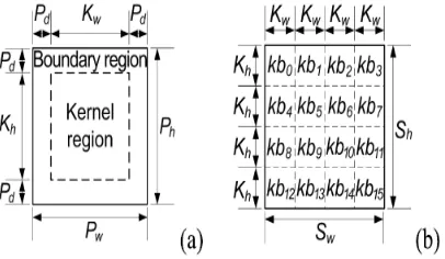
The basic unit used for data concealing by texture synthesis is referred to as a patch. A patch represents an image block of a source texture where its size is specified by the user. Fig. 1(a) illustrates the diagram of a patch. We can specify the size of a patch by its width (Pw) and height (Ph) dimensions. A patch contains the central part and an outer part where
the central part is the kernel region with size of Kw × Kh, and the part surrounding the kernel region are referred to as
the boundary region with the depth (Pd).
Fig 1: Patch and kernel blocks. (a) The diagram of a patch. (b) An illustration of non-overlapped kernel blocks subdivided from the source texture.
Given a source texture with the size of Sw×Sh, we can subdivide the source texture into a number of non-overlapped
kernel blocks, each of which has the size of Kw×Kh, as shown as Fig. 1(b). Let KB represent the collection of all kernel
blocks thus generated. We can employ the indexing for each source patch KBi ,ie, KB ={kbi |i=0 to ||KB||-1}. As an
example, given a source texture with the size of Sw×Sh = 128×128, and assume the size Kw×Kh as 32×32, then ‖KB‖ =
16 kernel blocks can be generated. Each element in KB can be identified as {kb0, kb1,..., kb15}. Then expand a kernel block with the depth Pd at each side to produce a source patch. If a kernel block is positioned around the boundary of a
source texture, we can use boundary mirroring such as symmetric contents of the kernel blocks to produce the boundary region. Similar to the kernel block, we can denote SP as the collection of all source patches and SPn=‖SP‖ as
the number of elements in the set SP. We can use indexing for each source patch SPi, i.e., SP ={spi|i = 0 to ‖SPk‖- 1}.
Given a source texture with the size of Sw× Sh, and kernel block has the size of Kw ×Kh, then number of source patches
SPn can be derived using equation
w h
n
w h
S S
S P
K K
Message Embedding Procedure
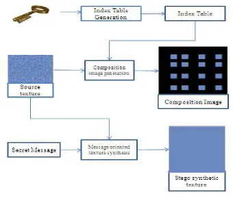
The message embedding procedure is illustrated in this section. Fig. 2 shows the three processes of message embedding procedure. Each process will be explained in the following sections. Many ideas and techniques have been proposed for secure data transmission, mainly concealing text in images. The simple method to do the same is Least Significant Bit replacement method in steganography [2]. Hiding a message inside Images is the most popular medium.
Fig 2: Flow chart
Index Table Generation Process
The first process is the index table generation. An index table is to record the location of the source patch set SP in the synthetic texture. The index table allows us to retrieve the synthetic texture and source texture completely.
First determine the dimensions of the index table (Tpw× Tph) by the given parameters Tw and Th, which are the width
and the height of the synthetic texture, intended to synthesize. The number of entries in this index table can be determined using equation
1 1
w w h h
n
w d h d
T P T P
T P
P P P P
Where, TPn represents the number of patches in the stego synthetic texture. For simplicity, chose appropriate
parameters for Tw, Th, Pw, Ph and Pd, in order to make the number of entries as an integer.
Given the number of patches SPn subdivided from the source texture, the procedure of patch distribution is to distribute
patches perfectly on the first-priority positions before pasting patches on the second-priority positions. Based on the resolution of the synthetic texture, we will have two conditions: the sparse distribution and dense distribution. When the number of source patches is less than or equal to the number of the first-priority positions (SPn≤ ‖L1‖), the patch
will be distributed sparsely. Inversely, when the number of source patches is greater than the first-priority position (SPn
Fig 3: Distribution of Source patches (a) sparse distribution, (b) dense distribution
The index table will be sprinkled with different values as shown in Fig. 4 having sixteen source patches (no. 1 to 16) and 128 blank locations with the initial value of -1.
Fig 4: Index Table
In this index table, the entries with non-negative values indicate the equivalent source patch ID subdivided in the source texture, while the entries with the value of -1 represents that these positions will be synthesized by referring to the secret message by the message-oriented texture synthesis.
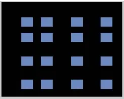
Patch Composition Process
The second process is to paste the source patches into a workbench to produce a composition image. First, establish a blank image as workbench where the size of the workbench is equal to the synthetic texture. By referring to the source patch IDs stored in the index table, paste the source patches into the workbench. During the pasting process, no overlapping of the source patches is encountered. This work embeds the secret message via the message-oriented texture synthesis to construct the final stego synthetic texture.
For the patch distribution, avoid positioning a source texture patch on the edges of the synthetic texture. This will strengthen the borders to be produced by message-oriented texture synthesis, enhancing the security provided by the synthetic texture. Fig. 5 illustrates the composition image where sixteen source patches pasted.
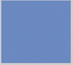
Message oriented texture synthesis Process
First of all, data (here text) is converted to 7 bit binary (each letter in the data). Binary data of each letter is divided and XOR ed with R-G-B Layer of the source patch. That is, first four LSB of the data is converted to decimal format for making red component. Then 5th and 6th LSB are converted to decimal to make green component. Finally, the MSB of data is taken and converted to decimal to make blue component. Then each data is bit XOR ed with the corresponding layer of source patch to make system reversible. If index table value is -1, then there is no source patch placed in the work bench for that location, hence patch containing the data can be placed in that location. Pasting of source patches in the final output will lead to overlapping of different patches, hence data loss will occur. To remove this condition, embed data only in kernel region. The stego synthetic image is shown in Fig 6.
Fig 6: Stego synthetic Texture
Message Extraction Procedure
The message extracting for the receiver side procedure contains four steps involves, generating the index table, recover the source texture, accomplish the texture synthesis, and extracting the secret message hidden in the stego synthetic texture, as shown in Fig. 7. In the receiver side, first load the stego-image and then input the key for authentication and decryption. With the secret key held in the receiver side, the same index table as the embedding procedure can be generated. The key should be same as used in sender side, else data decryption will fail. The next step is the source texture recovery.
Source Texture Recovery
Each kernel region and its corresponding order with respect to source texture can be recovered by comparing the index table. Then arrange kernel blocks based on their order, thus retrieving the source texture which is absolutely the same as the source texture.
Composition Image Generation
In the third step, apply the composition image generation to paste the source patches into a workbench to produce a composition image by attributing to the index table. This produces the composition image that is identical to the one produced in the embedding procedure.
Message Extraction
Fig 7: Extraction Process
III. RESULT AND DISCUSSION
For the implementation of this work Matlab R2013a is used. Data set includes images from texture library.
http://textures.forrest.cz/.
Embedding Capacity
For a fixed number of BPP, the larger the resolutions of the source texture Sw×Sh, the smaller the total embedding
capacity (TC). This is because the larger source texture will contain more source patches SPn that we want to paste
which doesn’t conceal any secret bits. This will reduce the number of embeddable patches (EPn) on the composition
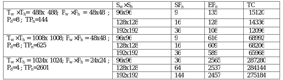
image, thus reducing the total embedding capacity. Table 1 gives a comparative study of variation of the maximum embedding capacities with varying source texture and stego synthetic texture size.
Synthesis Time
The total time taken to synthesize a stego image concealing data with 112×7 char is 6.064 sec. To retrieve data it takes only 4.303 sec. This proposed method extracts the embedded messages correctly. Table 1 provides the idea of how total embedding capacity related to number of source patches, the size of patch when synthetic texture size differs.
Table 1.Total Embedding capacity in bits our algorithm can provide
Sw ×Sh SPn EPn TC
Tw ×Th= 488x 488; Pw ×Ph = 48x48 ;
Pd=8 ; TPn=144
96x96 9 135 15120 128x128 16 128 14336 192x192 36 108 12096 Tw ×Th = 1008x 1008; Pw ×Ph = 48x48 ;
Pd=8 ; TPn=625
96x96 9 616 68992 128x128 16 609 68206 192x192 36 589 65968 Tw ×Th = 1024x 1024; Pw ×Ph = 24x24 ;
Pd=4 ; TPn=2601
96x96 36 2565 287280 128x128 64 2537 284144 192x192 144 2457 275184
Where, Sw ×Sh Source Texture Size, Tw ×Th : Synthetic texture size; Pw ×Ph : Patch size; Pd : Boundary depth ; TPn :
×Sh =192×192). In this work the maximal embedding capacity is 287280 bits (for Tw ×Th =1024×1024, Pw ×Ph =
24×24, Pd=4, Sw ×Sh =96×96).
IV.CONCLUSION
This work proposes a reversible message oriented data concealing algorithm by means of texture synthesis. XOR encryption is used for embedding message. Given an original source texture, our scheme can synthesize a large stego synthetic texture concealing secret messages. This method provides reversibility to recover the original source texture from the stego synthetic textures, making possible a second round of texture synthesis if needed. This algorithm can produce visually plausible stego synthetic textures even if the secret messages with bits 0 or 1 have an uneven appearance of probabilities. By this work the embedding capacity is increased from the range 30780 - 34398 to 275184 – 287280 with a small synthesis time (maximum 12 seconds). One possible future study is to expand the work to conceal images in the texture.
REFERENCES
[1] F. A. P. Petitcolas, R. J. Anderson, and M. G. Kuhn, “Information hiding a survey,” Proc. IEEE, vol. 87, no. 7, pp. 1062-1078, Jul. 1999 [2] Saleh Saraireh, “A secure data communication System using cryptography and Steganography,” IJCNC,Vol.5, No.3, May 2013.
[3] J. Fridrich, M. Goljan, and R. Du, “Detecting LSB steganography in color, and gray-scale images,” IEEE MultiMedia, vol. 8, no. 4, pp. 2228, Oct./Dec. 2001.