Power Control for Hybrid AC/DC Micro grid
using Implementation of FLC
R.Suga Priya, M.Sangeetha
Post Graduate Student M.E (Power System Engineering), The Kavery Engineering College, Tamilnadu, India
Assistant Professor, Department of EEE, The Kavery Engineering College, Tamilnadu, India
ABSTRACT: -In this paper hybrid AC/DC micro grid comprises of DC and AC sub grids interconnected by power electronic interfaces. But existing micro grids are purely AC or DC grids. The major purpose is to manage the power flow among all sources distributed throughout the different types of sub grids. The hybrid grid reduces the process of multiple DC-AC-DC or AC-DC-DC conversions in an individual grid where the number of converter stations for converting AC to DC or DC to AC power are reduced. These power generating stations interconnected to form a micro grid system needed number of multiple reverse conversations (AC-DC or DCAC) for consumer applications this results increase circuit complexity, cost and system have less reliability. The proposed grid can operate in both standalone and grid connected mode. Fuzzy controller is used for smooth power transfer.
KEYWORDS: -Hybrid micro grid, Proportional integral controller, Standalone, Grid connected mode.
I. INTRODUCTION
The increasing number of renewable energy sources and distributed generation (DG) requires new technique for the operation and management of the electricity grid to enhance proper power sharing. In the present power scenarios, when distributed generations are mentioned for small scale generations to meet the various customer demand. The coordination of these small scale generations may consist of photovoltaic, batteries, wind and fuel cells which are formed as Micro-grid [1]. Interest on micro grid is rapidly increasing as it is based on the renewable energy sources, which connects to utility grid and various types of loads. In the grid tied mode, it is connected with utility whereas in case of autonomous mode it is totally disconnected. In case of autonomous mode it becomes totally independent and fulfills the demands of customers from the renewable energy sources [2],[3]. Grid connected, Islanding mode, Transition mode. Therefore a suitable control strategy is required to coordinate the operation of DC sources AC sources and IC, which need a fast communication link reliability concern, which uses a decentralized control among which droop control method can be used for which proper power sharing between AC and DC micro grid.
II. SYSTEM STRUCTURE AND OPERATION MODES
Fig.1. A typical hybrid AC/DC micro grid.
A. Grid-Connected Mode
While the hybrid AC/DC micro grid is connected to the main utility grid, dg sources in the AC micro grid are expected to either generate a specified real/reactive power, or act as terminal voltage regulator with a specified amount of active power and variable reactive power [5]. On the other hand, the utility grid operates as slack bus to support the difference in the active/reactive power demand and to sustain the micro grid frequency. Similarly, in DC micro grid, DG sources would be controlled to generate a specified active power. However, the utility grid is still responsible for voltage support and power balance through the IC. According to Fig. 1 and neglecting the power losses, this mode can be described,
DC micro grid : (1)
AC micro grid:
In this mode the renewable energy sources in the micro grid can operate in maximum power point, energy storages can charge and non-renewable sources can be managed, e.g., for peak shaving purposes, loss reduction or economical goals. In the ac micro grid, DGs could also generate a specified reactive power, regulate terminal voltage or may be used for power quality aims [21]. These power management studies have been studied in DC micro grids [7], [8] and it is not intended to be followed in this paper.
B. Islanding Mode
Whenthehybridgridoperatesintheislandingmode, an interlinking converter acts as a converter and inverter mode to supply the power from AC micro grid to DC micro grid and DC micro grid to AC micro grid for balanced the power in both grids. In this mode Utility grid is not supplying power, Static switch is open, Feeder A, B, C is being supplied by Micro sources, Feeder D (not sensitive) is dead. In the islanding mode, the total load demand should be shared and managed autonomously by the existing DGs in the both micro grids, which involves rapid and flexible active/reactive power control strategies to minimize the micro grid dynamics. Different operating states may occur during islanding operation of the hybrid micro grid. For the sake of appropriate performance of the hybrid AC/DC micro grid under different grid conditions, four main operating states are considered in the islanding mode, as follows:
generation units in each micro grid will regulate its power to meet the load. In this state, the IC halts transferring power and can just supply reactive power for the AC micro grid. This state is expressed by,
(3)
DC micro-grid: (4)
AC micro-grid: (5)
Islanding state II: This state represents the case where the generated power in AC micro grid is deficient for the AC load demand but there is surplus power in the DC micro grid. Therefore, the required power should be supplied by the dc sources through the IC. In this state we have,
DC micro-grid:
AC micro-grid: , > , (7)
Islanding state III: This state is similar to state II, except that the power deficit occurs in the DC micro grid and the AC micro grid is in light load condition. Therefore, the AC micro grid supplies the required power for DC micro grid. In this case,
DC micro-grid : (9)
AC micro-grid : (10)
Islanding state IV: This operation state relates to the case during which the load demand in both AC micro grid and DC micro grid are greater than the maximum available sources capacity (overload condition). In this state, the IC halts transferring power and a proper load shedding strategy must be run to stabilize the grids. This state is described by,
(12)
DC micro-grid: (13)
AC micro-grid: (14)
III. DROOP CONTROL STRATEGY FOR INDIVIDUALMICRO GRIDS
(i)Control of DGS in the AC Micro grid
Power management based on droop control is currently well recognized in ac micro grids. Real power generation of a DG is specified based on frequency-droop (w-P) characteristic [4]. Since there is no dominant source to enforce the base frequency in the islanded micro grid, the frequency of the micro grid varies by means of demanded power variations. The main idea of this control is to increase the active power generation of DGs when the system frequency decreases. Similarly, for reactive power management voltage-droop (V-Q) is exploited. Reactive power generation of a DG is determined based on deviations in the bus voltage. Therefore, the DG source acts in response to the measured local voltage deviations caused by either the system or the local load‘s-P and V-Q characteristics could be described mathematically by,
(15)
(16)
IV. PROPOSED IC CONTROL FOR ISLANDING OPERATION
between the micro grids. In order to eliminate fast communication links, a modified droop based control strategy is proposed to attain desirable performance.
As discussed in the previous sections, during the islanding operation of the hybrid AC/DC micro grid different operating states might arise and the IC should recognize these states and manage the whole hybrid micro grid. The following decentralized control strategy is adopted for this purpose. The power management should determine the amount of active power that the IC must transfer from one micro grid to the other. In order to provide the power reference command, the DC bus voltage of the IC and the frequency of the AC micro grid are
Utilized as input to the power management system. Considering the electrical energy stored in the DC capacitor is,
(18)
Neglecting the switching losses in the converter ≈ , the dynamics in the DC capacitor energy is the difference of power transfer between AC and DC micro grids. Therefore,
On the other side, considering the w-P characteristic in the AC micro grid, The ―AC-DC droop‖ characteristic is shown in Fig.3.δw and are the dead zone bands for the allowable variation of angular frequency and DC voltage, respectively
Simplified equivalent model of the hybrid micro-grid.
V. FUZZY LOGIC CONTROL
L. A. Zadeh presented the first paper on fuzzy set theory in 1965. Since then, a new language was developed to describe the fuzzy properties of reality, which are very difficult and sometime even impossible to be described using conventional methods. Fuzzy set theory has been widely used in the control area with some application to power system. A simple fuzzy logic control is built up by a group of rules based on the human knowledge of system behavior. Furthermore, design of fuzzy logic controller can provide desirable both small signal and large signal dynamic performance at same time, which is not possible with linear control technique. Thus, fuzzy logic controller has been potential ability to improve the robustness of compensator. The basic scheme of a fuzzy logic controller is shown in Fig .7. and consists of four principal components such as: a fuzzy fiction interface, which converts input data into suitable linguistic values; a knowledge base, which consists of a data base with the necessary linguistic definitions and the control rule set; a decision-making logic which, simulating a human decision process, infer the fuzzy control action from the knowledge of the control rules and linguistic variable definitions; a de-fuzzy fiction interface which yields non fuzzy control action from an inferred fuzzy control action.
Rule Base: the elements of this rule base table are determined based on the theory that in the transient state, large errors need coarse control, which requires coarse in-put/output variables; in the steady state, small errors need fine control, which requires fine input/output variables. Based on this the elements of the rule table are obtained as shown in Table, with ‗ ‘ and ‗ _ ‘ as inputs.
FUZZYFICATION DECISION
MAKING DEFUUZZYFICATION
D(k)=d(k-i)+di(k)
De(k)=e(k)-e(k-i)
KNOWLEDGE
Rule Base Data Base
FLC
Error Amplifier
Crisp Value
Real
Input e(k)
Real Di(k)
Vdc_actual
Vdc_ref
Fuzzy µ(k)
Fuzzy µ(e)
-.08 -0.6 -0.4 -0.2 0 0.2 0.4 0.6 0.8 1
e,∆e
Fig.9. Membership functions for Input, Change in input, Output.
TABLE 1FUZZY RULES
VI. RESULTS
In order to demonstrate the proposed methods, simulation test have been carried out in this paper based on a typical hybrid AC/DC micro grid shown in Fig1. Using MATLAB/simulation. The system consists of an ac micro grid with conventional DG sources, a DC micro grid with two DC type sources and an IC links the two micro grids together and connected to the main utility grid. In this paper, grid connected mode was simulated by MATLAB and shows the DC bus voltage (V), AC RMS Voltage (V), frequency (HZ), total harmonic distortion (THD), when AC/DC loads are connected to the main utility grid, islanding mode when AC and DC load is varying, when both loads are in light load and over load condition and FLC in hybrid AC/DC micro grid.
NL NM NP EZ PP PM PL
0.8 1
0.4
0.2
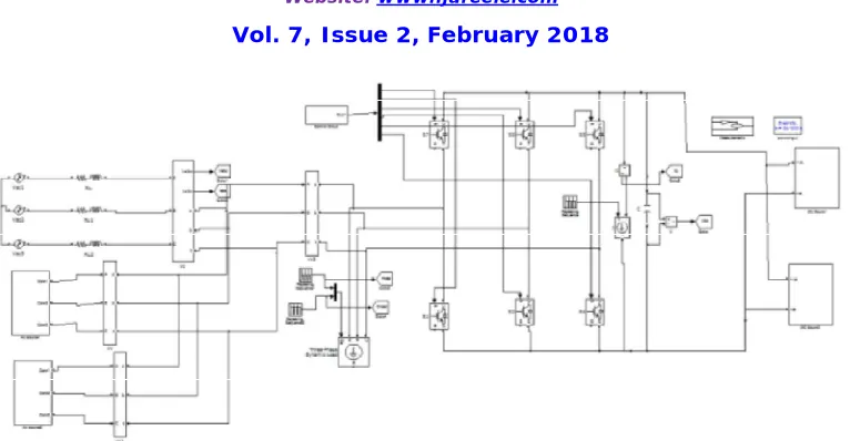
Case1: When AC/DC micro grid is connected to the main utility grid
Fig.10. Simulink diagram of hybrid AC/DC micro grid when connected to main utility grid.
Fig.10. Shows the simulink diagram of hybrid AC/DC micro grid when connected to main utility grid. In this DC load demand is high (400 KW), but two DC sources are not meeting the required load demand at time t = 1 sec DC load is suddenly drop to 200 KW as shown in fig.11.(a). and DC voltage has some disturbance is shown in fig.11.(b). To over come these problems Interlinking converter (IC) moves to inverting mode and tranfer sufficient power from AC side to DC side. At time t = 2 sec load is increased and approximately matches the
generated DC power is shown in fig.11.(a ).
Case2: Islanding mode when AC load is varying
Fig.12. Simulink diagram of islanding mode with AC variable load.
Fig.12. shows the simulinkdiagram of islanding mode with AC variable load. In this hybrid AC/DC micro grid is operated in transition from grid connecting mode to islanding mode. At time t = 1 sec micro grid is disconnected from the main utility grid and having AC load demand of active power of 900 KW and reactive power of 300 KVAR, is high, but two AC sources are not meeting the required load demand. In this condition AC load is drop to 800 KW and 250 KVAR as shown in fig.13.(a). and (c) which causes frequency drop as shown in fig.13.(e). In order to balance the power, The Interlinking converter (IC) shares the surplus power from
(c) Reactive power at AC side, IC (d)DC Voltage (V) (e) AC RMSVoltage (V) (f) Frequency (Hz).
Case 4: When both loads are in light load condition
Fig.14. Simulink diagram when both AC load and DC loads are in light load condition.
Fig.16. Shows the Simulink diagram when both AC load and DC loads are in light load condition. In this case two micro grids are initially operated in load condition that means that the load power in both AC and DC micro grids are less than total rating of
individual sources. So, the IC transfers no power. At time t = 1 sec load is increased in DC micro grid in which the power demand is greater than the DC generation shown in fig.17. (b). which causes voltage drop in DC link voltage as shown in fig.17. (d). at time t = 2 sec DC load is decreases and DC micro grid is enters the initial condition is shown in shown fig.17. (b). at time t = 3 sec ac load is increased and IC detects the frequency drop as shown in fig.17. (a) and (e).
Fig.16.Simulink diagram of both AC load and DC loads are in over load condition.
Fig.18. Shows the simulink diagram of both AC load and DC loads are in over load condition. In this both micro grids are primarily operating in light load condition. At t = 1 sec DC load is increased to 500 KW that is over loading power in increased in DC micro grid is shown in fig.19.(b). Which cause voltage disturbances as shown in fig.19.(d). In which the IC transfer the required power to AC side. At time t = 2 sec the AC load is also increased to 800 KW at active power and 280 KVAR at reactive power, that means the AC micro grid is in over load condition is shown in figs.19.(a) and (c). Which causes frequency drop is shown in
TABLE 2THD in grid current PI
CONTROLLER
FUZZY LOGIC CONTROLLER
THD 4.10% 0.04%
VII. CONCLUSION
In this paper hybrid AC/DC micro grid comprises of AC micro grid and DC micro grid interconnected by power electronic interfaces. The major purpose is to manage and control the power flow between the AC micro grid and DC micro grid through the AC source and DC source using the interlinking converter (IC). This conversion has been occurring between AC to DC or DC to AC using interlinking converter (IC) due to this conversion total harmonic distortion (THD) has occurred in grid current up to 4.10%. In the presence of fuzzy logic controller (FLC) these harmonics are reduced to 0.04%.
REFERENCES
[1]. N. Eghtedarpour and E. Farjah, Distributed charge/discharge control of energy storages in a renewable energy-based DC micro grid, IET Renew. Power Gen., vol. 8, no. 1, pp. 45–57, Jan. 2014.
[2]. A. Karabiber, C. Keles, A. Kaygusuz, and B. B. Alagoz, ―An approach for the integration of renewable distributed generation in hybrid DC/AC micro grids,‖ J. Renewable Energy, vol. 52, pp. 251–259, Apr. 2013.
[3]. P.C. Loh,D. Li, Y. K. Chai, and F. Blaabjerg, ―Hybrid AC-DC micro grids with energy storages and progressive energy flow tuning,‖ IEEETran. Power Electron., vol. 28, no. 4, pp. 1533–1543, Apr. 2013.
[4]. P. C. Loh, D. Li, Y. K. Chai, and F. Blaabjerg, ―Autonomous control of interlinking converter with energy storage in hybrid AC-DC micro grid,‖ IEEE Trans. Ind. Appl., vol. 49, no. 3, pp. 1374– 1382,May/Jun. 2013.