ISSN (Print) : 2320 – 3765 ISSN (Online): 2278 – 8875
I
nternational
J
ournal of
A
dvanced
R
esearch in
E
lectrical,
E
lectronics and
I
nstrumentation
E
ngineering
(An ISO 3297: 2007 Certified Organization)
Vol. 5, Issue 3, March 2016
Modified Perturb and Observe Algorithm for
Drift Avoidance in PV System Using Neural
Network
V.Mohanraj 1, T.poongundran 2
Assistant Professor, Dept. of EEE, Mount Zion College Engineering, Pudukkottai, Tamilnadu, India1
PG Student [Power Electronics], Dept. of EEE, Mount Zion College Engineering, Pudukkottai, Tamilnadu, India2
ABSTRACT: As the Photovoltaic System uses the solar energy as one of the renewable energies for the electrical energy production has an enormous potential. The PV system is developing very rapidly as compared to its counterparts of the renewable energies. The DC voltage generated by the PV system is boosted by the DC-DC Boost converter. The utility grid is incorporated with the PV Solar Power Generator through the 3-ı PWM DC-AC inverter, whose control is provided by a constant current controller. This controller uses a 3-ı phase locked loop (PLL) for tracking the phase angle of the utility grid and reacts fast enough to the changes in load or grid connection states , as a result, it seems to be efficient in supplying to load the constant voltage without phase jump. An artificial neuron is a device with many inputs and one output. By using artificial neuron networks, the control algorithm implemented in the boost converter enhances by reducing the response time and hence, transient response for this converter is improved.
KEYWORDS: PV system, DC-DC Boost converter, artificial neuron networks, utility grid.
I. INTRODUCTION
1.1 RENEWABLE ENERGY SOURCES:
Renewable energy is generally defined as energy that comes from resources which are naturally replenished on a human time scale such as sunlight, wind, rain, tides, waves and geothermal heat. Renewable energy replaces conventional fuels in four distinct areas: electricity generation, hot water/space heating, motor fuels, and rural (off-grid) energy services. Photovoltaic (PV) technology converts one form of energy (sunlight) into another form of energy (electricity) using no moving parts, consuming no conventional fossil fuels, creating no pollution, and lasting for decades with very little maintenance.
PV panels tend to work much better in cold weather than in hot climates (except for amorphous silicon panels). Add a reflective snow surface and the output can sometimes exceed the rating for the panel. Array currents up to 20% greater than the specified output have been reported. In general, PV materials are categorized as either crystalline or thin film, and they are judged on two basic factors: efficiency and economics. For remote installations where the actual space available for PV panels is often quite limited, the greater conversion efficiency of crystalline technology seems to have the advantage. It is also worth noting that the conversion efficiency of thin-film panels tends to drop off rather rapidly in the first few years of operation. Decreases of more than 25% have been reported. This performance deterioration must be taken into account when sizing the array for a multi-year project.
1.3 PV SYSTEM:
ISSN (Print) : 2320 – 3765 ISSN (Online): 2278 – 8875
I
nternational
J
ournal of
A
dvanced
R
esearch in
E
lectrical,
E
lectronics and
I
nstrumentation
E
ngineering
(An ISO 3297: 2007 Certified Organization)
Vol. 5, Issue 3, March 2016
Operating silently and without any moving parts or environmental emissions, PV systems have developed from being niche market applications into a mature technology used for mainstream electricity generation. A roof-top system recoups the invested energy for its manufacturing and installation within 0.7 to 2 years and produces about 95 percent of net clean renewable over a 30-year service lifetime.
1.4 Solar array
Conventional c-Si solar cells, normally wired in series, are encapsulated in a solar module to protect them from the weather. The module consists of a tempered glass as cover, a soft and flexible encapsulate, a rear back sheet made of a weathering and fire-resistant material and an aluminium frame around the outer edge. Electrically connected and mounted on a supporting structure, solar modules build a string of modules, often called solar panel. A solar array consists of one or many such panels. A photovoltaic array, or solar array, is a linked collection of solar panels. The power that one module can produce is seldom enough to meet requirements of a home or a business, so the modules are linked together to form an array.
Most PV arrays use an inverter to convert the DC power produced by the modules into alternating current that can power lights, motors, and other loads. The modules in a PV array are usually first connected in series to obtain the desired voltage; the individual strings are then connected in parallel to allow the system to produce more current. Solar panels are typically measured under STC (standard test conditions) or PTC (PVUSA test conditions), in watts. Typical panel ratings range from less than 100 watts to over 400 watts. The array rating consists of a summation of the panel ratings, in watts, kilowatts, or megawatts.The operating point on the characteristics of the PV module primarily depends on the impedance matching of the PV module with respect to the connected load. A DC-DC converter between the PV module and load acts as an interface to operate at MPP by changing the duty cycle of the converter generated by the MPPT controller and a general block diagram of PV system.
1.5 EXISTING SYSTEM
1.5.1 PERTURB AND OBSERVE:
In this method the controller adjusts the voltage by a small amount from the array and measures power; if the power increases, further adjustments in that direction are tried until power no longer increases. This is called the perturb and observe method and is most common, although this method can result in oscillations of power output. It is referred to as a hill climbing method, because it depends on the rise of the curve of power against voltage below the maximum power point, and the fall above that point. Perturb and observe is the most commonly used MPPT method due to its ease of implementation. Perturb and observe method may result in top-level efficiency, provided that a proper predictive and adaptive hill climbing strategy is adopted.
The operating point on the characteristics of the PV module primarily depends on the impedance matching of the PV module with respect to the connected load. A DC-DC converter between the PV module and load acts as an interface to operate at MPP by changing the duty cycle of the converter generated by the MPPT controller and a general block diagram of PV system.
1.5.2 FLOWCHART OF PERTURB AND OBSERVE:
ISSN (Print) : 2320 – 3765 ISSN (Online): 2278 – 8875
I
nternational
J
ournal of
A
dvanced
R
esearch in
E
lectrical,
E
lectronics and
I
nstrumentation
E
ngineering
(An ISO 3297: 2007 Certified Organization)
Vol. 5, Issue 3, March 2016
1.5.3 Drawbacks of existing systems:
Drift problem occurs for an increase in insolation and it will be severe for a rapid increase in insolation which generally occurs in cloudy days.
Drift problem is due to the lack of knowledge in knowing whether the increase in power is due to perturbation or due to increase in insolation.
The existing system MPPT algorithm has been tested for a step change in insolation level from 270 W/m 2 to 480 W/m 2 at 1.01s.
1.5.4 OBJECTIVE OF THE PROJECT
The PV system is developing very rapidly as compared to its counterparts of the renewable energies. The DC voltage generated by the PV system is boosted by the DC-DC Boost converter. The utility grid is incorporated with the PV Solar respond time improved. By using artificial neuron networks, the control algorithm implemented in the boost converter enhances by reducing the response time and hence, transient response for this converter is improved.
II. PROPOSED SYSTEM
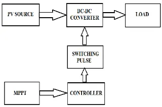
3.1 BLOCK DIAGRAM:
The operating point on the characteristics of the PV module primarily depends on the impedance matching of the PV module with respect to the connected load. A DC-DC converter between the PV module and load acts as an interface to operate at MPP by changing the duty cycle of the converter generated by the MPPT controller and a general block diagram of PV system.
Fig 3.1 Block diagram of proposed system
3.2 DESCRIPTION OF BLOCK DIAGRAM:
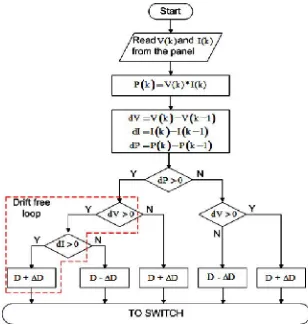
Perturb and Observe (P&O) maximum power point tracking (MPPT) algorithm is a simple and efficient tracking technique. However, P&O tracking method suffers from drift in case of an increase in insolation (G) and this drift effect is severe in case of a rapid increase in insolation. Drift occurs due to the incorrect decision taken by the conventional P&O algorithm at the first step change in duty cycle during increase in insolation.
A modified P&O technique is proposed to avoid the drift problem by incorporating the information of change in current (I) in the decision process in addition to change in power (P) and change in voltage (V ). The drift phenomena and its effects are clearly demonstrated in this paper for conventional P&O algorithm with both fixed and adaptive step size technique.
ISSN (Print) : 2320 – 3765 ISSN (Online): 2278 – 8875
I
nternational
J
ournal of
A
dvanced
R
esearch in
E
lectrical,
E
lectronics and
I
nstrumentation
E
ngineering
(An ISO 3297: 2007 Certified Organization)
Vol. 5, Issue 3, March 2016
3.3 FLOWCHART OF MODIFIED P&OMPPT:
Fig. 3.3flowchart of modified p&o mppt
3.4 MODIFIED CIRCUIT DIAGRAM
Fig.3.4 .modified circuit diagram
The operating point on the characteristics of the PV module primarily depends on the impedance matching of the PV module with respect to the connected load. A DC-DC converter between the PV module and load acts as an interface to operate at MPP by changing the duty cycle of the converter generated by the MPPT controller and a general block diagram of PV system. Where V and I are PV voltage and current respectively. The equivalent input resistance (R) of the converter as seen by the PV module. it can be noticed that by changing the duty cycle the operating point can be changed as Req changes and the MPPT controller should change the duty cyclein order to track the peak power.Perturb and Observe (P&O) maximum power point tracking (MPPT) algorithm is a simple and efficient tracking technique. However, P&O tracking method suffers from drift in case of an increase in insolation (G) and this drift effect is severe in case of a rapid increase in insolation. Drift occurs due to the incorrect decision taken by the conventional P&O algorithm at the first step change in duty cycle during increase in insolation.
MPPT:
ISSN (Print) : 2320 – 3765 ISSN (Online): 2278 – 8875
I
nternational
J
ournal of
A
dvanced
R
esearch in
E
lectrical,
E
lectronics and
I
nstrumentation
E
ngineering
(An ISO 3297: 2007 Certified Organization)
Vol. 5, Issue 3, March 2016
Fig.4.6.MPPT controller
This article about the application of MPPT concerns itself only with PV solar. Solar cells have a complex relationship between temperature and total resistance that produces a non-linear output efficiency which can be analyzed based on the I-V curve. It is the purpose of the MPPT system to sample the output of the PV cells and apply the proper resistance (load) to obtain maximum power for any given environmental conditions MPPT devices are typically integrated into an electric power converter system that provides voltage or current conversion, filtering, and regulation for driving various loads, including power grids, batteries, or motors.
4.5 Neural network:
An Artificial Neural Network (ANN) is an information processing paradigm that is inspired by the way biological nervous systems, such as the brain, process information. The key element of this paradigm is the novel structure of the information processing system. It is composed of a large number of highly interconnected processing elements (neurons) working in unison to solve specific problems. ANNs, like people, learn by example. An ANN is configured for a specific application, such as pattern recognition or data classification, through a learning process. Learning in biological systems involves adjustments to the synaptic connections that exist between the neurons. This is true of ANNs as well.
Fig.4.8 Configuration of neural network
ISSN (Print) : 2320 – 3765 ISSN (Online): 2278 – 8875
I
nternational
J
ournal of
A
dvanced
R
esearch in
E
lectrical,
E
lectronics and
I
nstrumentation
E
ngineering
(An ISO 3297: 2007 Certified Organization)
Vol. 5, Issue 3, March 2016
(loops) i.e. the output of any layer does not affect that same layer. Feed-forward ANNs tend to be straight forward networks that associate inputs with outputs.
III. SIMULATION AND RESULTS MATLAB:
5.4 PROPOSED SYSTEM SIMULATION DIAGRAM
Fig.5.1. Simulation for proposed system
5.4.2 SIMULATION RESULT FOR PROPOSED SYSTEM
ISSN (Print) : 2320 – 3765 ISSN (Online): 2278 – 8875
I
nternational
J
ournal of
A
dvanced
R
esearch in
E
lectrical,
E
lectronics and
I
nstrumentation
E
ngineering
(An ISO 3297: 2007 Certified Organization)
Vol. 5, Issue 3, March 2016
Fig.5.4.simulation result for proposed system difference of tme duration
5.1 COMPARISON TABLE
PARAMETER Respondent point in (v)
Respondent time in (s)
PI controller 380 to 414 0.01 to 0.5
ANN controller 414 (constant) 0.01 (constant)
IV. CONCLUSION
ISSN (Print) : 2320 – 3765 ISSN (Online): 2278 – 8875
I
nternational
J
ournal of
A
dvanced
R
esearch in
E
lectrical,
E
lectronics and
I
nstrumentation
E
ngineering
(An ISO 3297: 2007 Certified Organization)
Vol. 5, Issue 3, March 2016
REFERENCES
[1] N. Femia, G. Petrone, G. Spagnuolo, and M. Vitelli, “Optimization of perturb and observe maximum power point tracking method,” IEEETrans. Power Electron., vol. 20, no. 4, pp. 963–973, Jul. 2005.
[2]A. Pandey, N. Dasgupta, and A. K. Mukerjee, “High-performance algorithms for drift avoidance and fast tracking in solar mpptsystem,”IEEE Trans. Energy Convers., vol. 23, no. 2, pp. 681–689, Jun. 2008.
[3] M. A. Algendy, B. Zahawi, and D. J. Atkinson, “Assessment of perturb and observe mppt algorithm implementation techniques for pv pumping applications,” IEEE Trans. Sustain. Energy, vol. 3, no. 1, pp. 21–33,Jan. 2012.
[4] S. B. Kjaer, “Evaluation of the hill climbing and the incremental conductance maximum power point trackers for photovoltaic power systems,”
IEEE Trans. Energy Convers., vol. 27, no. 4, pp. 922–929,Dec. 2012.
[5] T. Esram, J. W. Kimball, P. T. Krein, P. L. Chapman, and P. Midya,“Dynamic maximum power point tracking of photovoltaic arrays usingripple correlation control,” IEEE Trans. Power Electron., vol. 21, no. 5,pp. 1282–1291, Sep. 2006.
[6] E. Mamarelis, G. Petrone, and G. Spagnuolo, “Design of a sliding mode controlled sepic for pvmppt applications,” IEEE Trans. Ind. Electron.,vol. 61, no. 7, pp. 3387–3398, Jul. 2014.
[7] M. A. G. de Brito, L. Galotto, L. P. Sampaio, G. A. e Melo, and C. A. Canesin, “Evaluation of the main mppt techniques for photovoltaic applications,” IEEE Trans. Ind. Electron., vol. 60, no. 3, pp. 1156–1167,Mar. 2013.
[8] H. S.-H. Chung, K. K. Tse, S. Y. R. Hui, C. M. Mok, and M. Ho,“A novel maximum power point tracking technique for panels using asepic or cuk converter,” IEEE Trans. Power Electron., vol. 18, no. 3, pp.717–724, May. 2003.
[9] F. Paz and M. Ordonez, “Zero oscillation and irradiance slope tracking for photovoltaic mppt,” IEEE Trans. Ind. Electron., vol. 61, no. 11, pp.6138–6147, Nov. 2014.