Design and Implementation of Photo-voltaic Based
STATCOM for Power Quality Issues in Domestic
Grid
B.Shafi
1, T.Elayabharathi
2PG Student [Power Systems], Dept. of EEE, VMKV Engineering College, Salem, Tamilnadu, India 1 Assistant Professor, Dept. of EEE, VMKV Engineering College, Salem, Tamilnadu, India 2
ABSTRACT: Solar PV converts solar energy directly into electricity without any intermediate conversion stage. As this process is eco-friendly and the solar radiation is cost free, solar energy harvesting through PV is a leading area of research in the renewable energy sector today. The efficiency of the present available domestic power in the market is very low due to multiple conversion stages and centralized application. A STATCOM with multi-rated PV sources is implemented in this project to reduce Power quality issues in domestic power supply. A novel strategy has been introduced to implement hardware prototype of proposed system using dSpic controller. The Total Harmonic Distortion (THD) of the output is also measured to verify proposed system suitable in real time.
KEYWORDS: dSPIC controller, STATCOM, Converters, MATLAB/SIMULINK, , Total Harmonic Distortion(THD).
I.INTRODUCTION
The growth in the global energy consumption is predicted to be 1.6-1.7% per year. The global consumption is going to hit 28TW by the year 2050. As the demand for energy is rising day by day and most of the global power demand is supplied by burning fossil fuels, renewable energy will contribute the global effort to meet the challenges of energy rise and climatic changes by providing clean energy In the centralized configuration, a number of PV modules are connected in series (called a PV string), and multiple PV strings are connected to a main STATCOM using diodes. Although the large, centralized STATCOM offers economies of scale, partial shading or any mismatch between the PV modules causes a substantial drop in the generated power output. The STATCOM solution employs the opposite approach by using a small STATCOM for individual MPP tracking of each PV module, maximizing possible energy harvesting. Therefore, reducing or even losing the output of a single module due to partial shading or an STATCOM failure has a minimal impact on the overall system performance. However, the main drawback of the STATCOM concept is a higher initial equipment cost per peak watt. This increased cost is due to the use of an STATCOM for each panel with much of the functionality of a centralized STATCOM. In smaller PV systems, such as residential applications, the STATCOM price has less effect on the overall cost, and therefore, STATCOMs are the preferred solution. As the price of STATCOMs comes down, this technology will be more attractive in other applications.
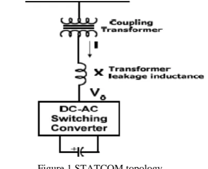
String technology is another configuration for PV systems, where a string of PV modules is connected to a single inverter integrated with an MPP tracker. Therefore, the string inverter can avoid most of the weaknesses of the centralized configuration. Nonetheless, the string technology has a power limit due to a limited number of series connections. The STATCOM [1] solution is an enhanced version of the string topology and ensures optimum energy harvesting and cost. In its conventional configuration, several strings are interfaced with their own MPP-tracked dc–dc converter to a common inverter as shown in Fig. 1. The STATCOM approach allows the integration of strings with different features with respect to the manufacturing technology, geographic orientation, and number of modules per string. It also enables the enhanced operation of the PV systems in partial shading conditions when the PV strings are at different irradiance levels and operating temperatures. The conventional STATCOM [4] PV topology has the disadvantage of poor conversion efficiency because of two stages of power conversion and the use of several bulky limited-lifetime electrolytic capacitors in the main dc-link.
In this Paper, a simple Static Compensating (STATCOM) scheme using a Cascaded Five-level inverter-based multilevel inverter is proposed. The main objective of this Paper is to ensure the DC Source voltage stability of the inverters during both balanced and unbalanced load conditions and also to reduce the THD at the point of coupling of the STATCOM from 22.54% as reported in reference [1], hence increasing the overall Power Quality and reliable operability of the STATCOM. Similar to the conventional multi-string topology, the proposed inverter can handle an arbitrary amount of PV strings with different electrical parameters and working conditions. However, the proposed topology has a single stage of soft-switched power conversion with no electrolytic capacitor in the link. Therefore, this converter is expected to have an improved efficiency, high power density, and enhanced reliability.
II.PROPOSED PV STATCOM
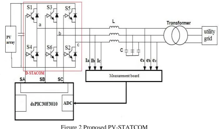
The soft-switched PV STATCOM with multi-rated PV source is shown in Fig. 2. The number of the input PV strings as well as their characteristics, operating voltages, and power levels is completely arbitrary. The proposed STATCOM can individually collect the maximum possible power of each string regardless of its location, orientation, irradiation level, or operating temperature. A capacitor is placed on primary side of the transformer for soft switching and to behave as passive snubbers as well. In this way, they provide paths for the leakage inductance currents of the transformer when the switches are turned OFF and avoid voltage spikes [1].
Figure 2 Proposed PV-STATCOM
A. Control Scheme
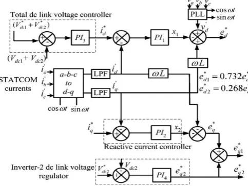
The Fig.4 shows the Control circuit topology of the cascaded Five-level inverter based STATCOM and Fig.5 shows the MATLAB SIMULINK Model of the Proposed Control circuit topology of the STATCOM.
Figure 3 Control circuit topology of the cascaded Five-level inverter based STATCOM
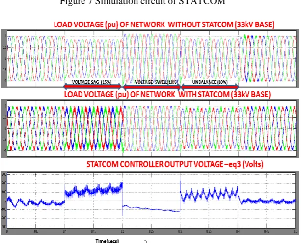
The function of the STATCOM controller is that if the power generated by the source is more than load demand connected downstream of the PCC, the excess power flows back towards the main grid. A substantial amount of this reverse power flow may cause voltage to rise on the distribution feeder more than the allowable limit (typical ± 5%) specified by the utility standards.
In addition, a STATCOM voltage magnitude controller is designed to regulate the PCC bus voltage through a PI controller. The ac voltage controller generates the desired reactive current reference for the Reactive current controller. In the design of the STATCOM controller, it is essential to have good dynamic response in the transient period and to ensure minimal harmonics at steady state. The ac voltage magnitude controller acts as both as a transient modulation-index controller and a steady-state modulation-modulation-index controller to achieve the goals of good transient response and minimal steady-state harmonics respectively.
A. Controller Equations:
Total DC Source Voltage Controller
ed*=Vd-[Vdc(ref) -(Vdc1+Vdc2)-Id']+kIq' (1)
STATCOM Voltage Magnitude Controller
eq*1=1-sqrt(Vd*Vd+Vq*Vq) (2)
Inverter DC Source Voltage Regulator
eq*2=Vdc(ref1)-Vdc2 (3)
Reactive Power
eq*3=[-(Iq*-Iq')-kId']-eq*2) (4)
III. SWITCHING ALGORITHM OF THE PROPOSED CONVERTER
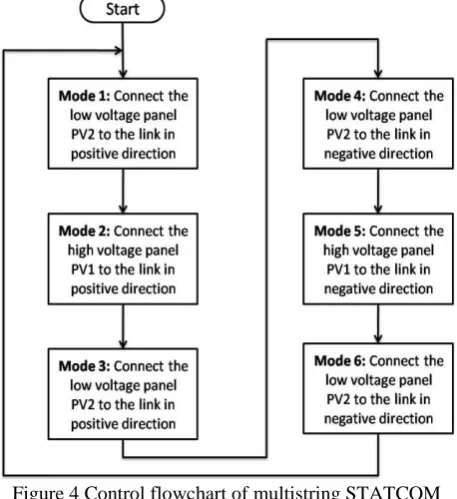
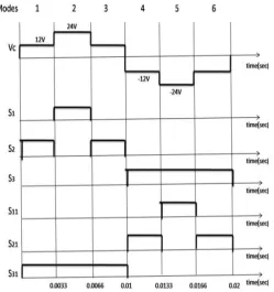
The operation of the proposed soft-switched STATCOM consists of several modes in each cycle depending on the number of PV panels connected. The switching flowchart of the converter is shown in Figure 4. The described switching algorithm can be extended to higher number of input solar PV panels. The entire 50Hz operating cycle can be divided into six modes with time period of 0.0033 seconds each. Total time period of cycle is 0.02 seconds.
Mode 1 [see Fig. 5(a)]: Two PV-side switches (S2 and S31) are turned ONto connect the PV string with the lower instantaneous voltage to the STATCOM in the positive direction. This mode runs until 0.0033 seconds. Subsequently, the switches are turned OFF. In figures 5 and 6, it is assumed that PV1 voltage is higher than PV2 voltage. Therefore, PV2is connected to the link in mode 1.
Figure 4 Control flowchart of multistring STATCOM
Mode 2[see Fig. 5(b)]: The switches(S1 and S31) are turnedONto connect the PV string with the higher instantaneous voltage ie PV1 to the STATCOM in the positive direction. The switches are turned OFF after 0.0066 seconds.
Mode 3 [see Fig. 5(c)]: For obtaining a sinusoidal waveform at the output, the PV panel with lower instantaneous voltage is again connected to the STATCOM in positive direction. The PV-side switches(S2 and S31) are again turned ON.These switches are turned OFF after 0.01 seconds. The positive half cycle of the output waveform is completed after Mode 3. The described sequence of the PV string is important and should be followed flawlessly to operate the converter properly. If, for instance, the highest PV voltage is mistakenly connected to the link in mode 1output waveform will be distorted.
Mode 4 [see Fig. 5(d)]: The negative half cycle starts with connecting the PV string with the lower instantaneous voltage ie PV2 to the STATCOM in the negative direction. Switches(S21 and S3) are turned ONto connect the PV string to the STATCOM. This mode runs until 0.0133 seconds and subsequently, the switches are turned OFF.
(a) Mode 1
(b) Mode 2
(c) Mode 3
(d) Mode 4
(f) Mode 6
Figure 5 Operating modes of PV STATCOM
Figure 6 STATCOM output voltage and switching sequence
Mode 6 [see Fig. 5(f)]: The switches (S21 and S3) are again turned ON to connect the PV string with the lower instantaneous voltage ie PV2 to the inverter in the negative direction. The switches are turned OFF after 0.02 seconds to complete the entire operating cycle.
IV. SIMULATION RESULTS
Figure 7 Simulation circuit of STATCOM
Figure 8 Output voltage of STATCOM
Figure 9 Output voltage of transformer
0 0.01 0.02 0.03 0.04 0.05 0.06
-300 -200 -100 0 100 200 300
time(sec)
tr
an
sf
or
m
er
o
/p
vo
lta
ge
(V
The inverter output voltage was read back into the machine to calculate the Total Harmonic Distortion (THD) through Matlab FFT analysis. The THD was measured to be 28.74% without the use of filter circuit as shown in figure 10(a). A simple filter circuit was designed to reduce the harmonics in the inverter output and thus reducing the THD. After connecting the filter circuit at the output, the THD was measured 10.83% as in figure 10(b). The THD was measured considering three cycles of each waveform. THD can be further reduced by proper design of filtering circuits to obtain pure sinusoidal output.
(a) Without filter
(b) With filter
Figure 10 THD Analysis for proposed STATCOM
45.94 45.95 45.96 45.97 45.98 45.99 46 46.01 46.02 46.03 -10
-5 0 5
Selected signal: 2302 cycles. FFT window (in red): 3 cycles
Time (s)
0 100 200 300 400 500 600 700 800 900 1000
0 5 10 15 20 Frequency (Hz) Fundamental (50Hz) = 9.788 , THD= 28.74%
M a g ( % o f F u n d a m e n ta l)
85.35 85.36 85.37 85.38 85.39 85.4 85.41 85.42 85.43 85.44 -10
-5 0 5
Selected signal: 4272 cycles. FFT window (in red): 3 cycles
Time (s)
0 100 200 300 400 500 600 700 800 900 1000
0 1 2 3 4 5 6 7 8 Frequency (Hz) Fundamental (50Hz) = 9.747 , THD= 10.83%
V. CONCLUSION
A single stage soft-switched STATCOM for PV systems was simulated using MATLAB/SIMULINK tool and prototype was implemented by interfacing with dSPIC controller. This multi-rated source STATCOM can have an arbitrary number of PV strings and is able to obtain the maximum possible power of each string independently. The PV strings can be of different electrical parameters and working conditions. Simulated digital gate pulses are provided to the switches by dSPIC controller. A single phase 50Hz transformer is responsible for boosting the voltage to required output level. Small ac capacitors on primary side of the transformer realize soft-switching operation. They also behave as passive snubbers to avoid voltage spikes. The control scheme and the switching algorithm of the proposed STATCOM were described. The output of STATCOM is also read by machine to measure the THD using Matlab FFT analysis. THD of the output waveform was reduced to 10.83% using filter circuits.
REFERENCES
[1] C. S. de Araujo and J. C. Castro, “Vectors analysis and control of advanced static VAR
[2] compensators,” IEE Proceedings-C, vol. 140, no. 4, Jul. 1993, pp. 299–306.
[3] A. H. Norouzi and A. M. Sharaf, “Two control scheme to enhance the dynamic performance of the STATCOM and SSSC,” IEEE Trans. On
Power Delivery, vol. 20, no. 1, Jan. 2005, pp. 435–442.
[4] R. Mienski, R. Pawelek, and I. Wasiak, “Shunt compensation for power quality improvement using a STATCOM controller: modeling and
simulation,” IEE Proc.- Gener. Transm. Distrib., vol. 151, no. 2, , Mar. 2004,pp. 274– 280.
[5] Hung-Chi Tsai, Chia-Chi Chu. Member, IEEE, and Sheng-Hui Lee Student Member, IEEE “ Passivity-based Nonlinear STATCOM Controller
Design for Improving Transient Stability of Power Systems” 2005 IEEE/PES Transmission and Distribution Conference & Exhibition: Asia and Pacific Dalian, China
[6] N. C. Schaoo, B. K. Panigrahi, P. K. Dash, and G. Panda, “Application of a multivariable feedback linearization scheme for STATCOM
control,”Electric Power System Research,vol. 62, no. 2, Jul. 2002, pp. 81–91.
[7] H. Sira-Ramirez, R. A. Perez-Moreno, R. Ortega, and M. Garcia-Esteban, “Passivity- based controllers for the stabilization of DC-to-DC
power converters,” Automatica, vol. 33, no. 4, pp. 499–513.
[8] G. E. Valderrama and P. M. amd A. M. Stankovic, “Reactive power and unbalance compensation using STATCOM with dissipativity-based
control,” IEEE Trans. on Control Systems Technology, vol. 9, no. 5, Sep. 2001,pp.718–727.
[9] H. Keyhani and H. A. Toliyat, “A soft-switching three-phase ac–ac con-verter with a high-frequency ac link,” in Proc. Energy Convers. Congr.
Expo., 2012, pp. 1040–1047.
[10] H. Keyhani, H. A. Toliyat, M. H. Todorovic, R. Lai, and R. Datta, “Isolated soft-switching HFAC-link 3-phase ac–ac converter using a
single-phase HF transformer,” in Proc. IEEE 38th Annu. Conf. Ind. Electron. Soc., 2012, pp. 512–517.
[11] I. D. Kim, and G. H. Cho, "New bilateral zero voltage switching AC/AC converter using high frequency partial-resonant link," Industrial
Electronics Society, 1990. IECON '90., 16th Annual Conference of IEEE , vol., no., pp.857-862 vol.2, 27-30 Nov 1990. L. Yi-Hung and L.
Ching-Ming, “Newly-constructed simplified single-phase multistring multilevel inverter topology for distributed energy resources,” IEEE
Trans. power Electron., vol. 26, no. 9, pp. 2386–2392, Sep. 2011.
[12] R. Lai, F, Wang, R. Burgos, Y. Pei, D. Boroyevich, B. Wang, T.A. Lipo, V.D. Immanuel, and K.J. Karimi, "A Systematic Topology
Evaluation Methodology for High-Density Three-Phase PWM AC-AC Converters," Power Electronics, IEEE Transactions on , vol.23, no.6, pp.2665-2680, Nov. 2008.
[13] M. Rashid, Power Electronics Handbook - Devices, Circuits, and Applications, 3rd Edition, New York: Elsevier, 2010.
[14] J. Itoh, D. Matsumura, S. Kondo, A. Odaka, and H. Ohguchi" "A novel control strategy for high-frequency AC-link ACIAC direct converter