Vol. 6, Issue 10, October 2017
Autotuning Control Based PID Implementation
for CSTH Process
T.Rajesh1, Dr.G.M.Tamil selvan2
, R.Raakesh
3, J.Rahul3 , B.Ram Kumar3
Assistant Professor, Dept. of EIE, Bannari Amman Institute of Technology, Sathyamangalam, Tamilnadu, India1
Associate Professor, Dept. of EIE, Bannari Amman Institute of Technology, Sathyamangalam, Tamilnadu, India2
UG Students, Dept. of EIE, Bannari Amman Institute of Technology, Sathyamangalam, Tamilnadu, India3
ABSTRACT:In all Process Industries, measurement and control of level, temperature, pressure and flow parameters
are very vital. Real time systems provide many challenging control problems due to their dynamic behaviour, uncertainty, time varying parameters, constraints on manipulated variables, dead time on input and measurements, interaction between manipulated and controlled variables and unmeasured frequent disturbances. Because of the inherent nonlinearity, most of the chemical process industries are in need of modern control techniques. Nonlinear systems like conical tanks, Continuous Stirrer Tank Heater system find wide applications in gas plants and petrochemical industries. The advantages like better disposal of solids, easy mixing and complete drainage of solvents such as viscous liquid in industries. In CSTH system non-linearity exists due to its variation in cross-sectional area. Because of the non-linearity, level control is a challenging task and it demands for implementation in real time. The nonlinearities also exists due to the saturation-type introduced by maximum or minimum allowed level in tanks, valve geometry, flow dynamics, pumps and valves. In this project we have proposed Autotuning Control Based Proportional Integral and Derivative Implementation for CSTH Process where PID controller is autotuned for CSTH process in temperature and level measurement control.
KEYWORDS: CSTH, PID, Manipulated Variable, Control Variable, HART, Autotuning, Dead time.
I.INTRODUCTION
Continuous stirred tank Heater is one of the included parts of the chemical plant. It has common applications in industry and a lot of features of additional types of heaters. It is a vital factor of many chemical industries. The study of a CSTH system is a source for the study and control of chemical heaters. Control of its considerations is a very essential task. It is necessary to keep the volume, temperature and density of the mixed of cold water in the desired limits. The distinction may lead to many terrible things causing injury to the people and surroundings. A CSTH is a well stirred tank into which the flows continuously and then the product passed out. It can be clear to have a reacting tank and that rotates continuously when the process carried out. CSTH is a container in which the mechanisms are constantly stirred to make certain their suitable mixing to attain a specific output. The aim is to raise the temperature of the inlet stream to a desired value. A heat transfer fluid is spread throughout a jacket to heat the fluid in the tank. Due to easy implementation and benefit of PID controller, it is executed in the design of CSTH process to progress the system's transient response for zero steady state error in addition to minimizing the settling time and the peak undershoot and overshoot.
PID Controller- The most basic and pervasive control algorithm used in the feedback control is the PID control algorithm. PID control is a widely used control strategy to control most of the industrial automation processes because of its remarkable efficiency, simplicity of implementation and broad applicability. Long history of its practical use and proficient working dynamics are some of the pivotal reasons behind the large acceptance of the PID control. A PID controller attempts to correct the error between a measured process variable and a desired set point by calculating and
Vol. 6, Issue 10, October 2017
model, gain tuning of the PID controller is done using Cohen Coon tuning method or Zeiger Nichols method which is implemented in the real time system to get optimum settling time and rise time. Fuzzy logic Controller- Fuzzy logic is a form of many values logic which deals with reasoning that is approximate rather than fixed and exact. Compared to traditional binary sets (where variables may take on true or false values), fuzzy logic variables may have a truth value that ranges in degree between 0 and 1. Fuzzy logic has been extended to handle the concept of partial truth, where the truth values may range between completely true and completely false. Fuzzy logic has been applied to many fields from control theory to artificial intelligence. Fuzzy logic has rapidly become one of the most successful of today’s technology for developing sophisticated control systems. It is interesting to note that the success of fuzzy logic control is largely due to the awareness to its many industrial applications. But the fuzzy algorithm cannot adapt for large range of working environments.
II.SYSTEM MODEL AND ASSUMPTIONS
Introduction-In this chapter the basic introduction and the test that has been taken in this research work is presented. Here real time model is designed for controlling the liquid level in CSTH process. The process model is analysed for different types of inputs with LabVIEW using simple cost effective Data Acquisition (DAQ) Card and Fuzzy logic PID controller is used to produce effective results which is implemented in MATLAB . The basic process control system as shown in Figure 1 consists of a control loop. This has four main components which are
A measurement of the state or condition of a process.
A controller calculating an action based on the measured value against a preset or desired value (set point).
An output signal resulting from the controller calculation which is used to manipulate the process action through some form of actuator.
Fig.1 Block Diagram of Process Control System
CSTH Process Control Setup- The plant in the department of Electronics and instrumentation engineering at Bannari Amman institute of technology is the hot and cold water is mixed and heated using steam through a heating coil in the stirred tank heater. The tank with well stirred and mixed hot water which implies that the temperature in the tank is examined to be the same as the outflow temperature. The tank has a cylindrical cross section with a height of 60 cm and volume 91.
Fig.2 Experimental setup for CSTH process
Vol. 6, Issue 10, October 2017
The three wires Resistive temperature detector’s(RTD’s) are used to measure the temperature at different points of process and produces the output voltage range of 0-5V which is calibrated to 0℃ to 250℃.
In this Lab VIEW program, the analog input voltage from the CSTH process station is acquired through the analog input icon from the DAQ (RTD). The control and simulation (while) loop used in this program is related to the practical control loop is Shown in the Block Diagram Figure (2). DAQ is the device interfaces between the Real time hardware and the PC. DAQ digitizes incoming analog signals from the CSTH process station. In the front panel is shown in the Figure (3) set point=60 cm and 45°C is given and SCR to stops. The real time process variable is compared with the given set point 60 cm and 45° in terms of voltage using a comparator. The error value from the comparator is given to the SCR. The Kc, Ʈi, Ʈd values given to the PID controller is achieved from the Z-N method of controller tuning method. From the obtain value the transfer function for the process is originated from the corresponding voltage and time seconds values for each °C of temperature of the RTD. The output from the SCR controller is given to the analog output icon (DAQ Assistant 2). When the DAQ Output (0-5) V, I-P Converter (3-15) PSI, level and temperature, 60 cm and 45°C set point is reached, 5V is generated in the analog output indicator. For the corresponding level and temperature upto the set point reaches the corresponding intermediate level and temperature as well as voltages values are displayed in the Front panel. When the set point is reached, the SCR which in turn stops the temperature of water into the tank.
Fig.3 Block Diagram for Level Control
Vol. 6, Issue 10, October 2017
III. PROCESS DESCRIPTION AND EQUATIONS
The open loop response is plotted and the values obtained from plot like percentage change in level (Q%), delay time (td), the time taken by the level are used for getting mathematical model of the conical tank. The model for first order process is as in the equation 1.
The First Order Process with Time Delay (FOPTD) model is,
Gs= (Kp e^(-t) d^s)/(τs+1) …(1)
Time constant =960 seconds
Kp= (% change in output)/(% change in input ) …(2)
Gs= (64.08 e^-11s)/(960 s+1) …(3)
Equation 2 indicated above is the obtained mathematical model for the entire operating range of CSTH process.
IV. CONTROLLER DESIGN
Gain scheduling is a method to control the controllers and it is a familiar technique of industrial control and it is used when a plant is subject to large variation in its operating state, a circumstances that is typical in industry. Autotuning controllers are one such approach, which provides satisfactory control for different types of operating point of the system. The standard conventional form of PID controller is,
C(S) = Kc (1 + 1/τ_iS + τ_DS) …(1)
Kc = Proportional gain
τi = Integration time
τd = Derivative time
Fig.5 Autotuning Controller Design
Vol. 6, Issue 10, October 2017
process models, typically first-order dynamics with time delays. The controller parameters are then determined by a variety of control design methods. Relay auto-tuning is another widely used approach that has proven to be robust and that brings attractive theoretical properties as well.
Upid (t) = Kp e(t) + Ki e(t) dt + Kd d/dt e(t) …(1)
A remarkable property of a controller with integral action is that it gives the correct steady state, if a steady state exists, even for nonlinear processes. Predicting a noisy signal by linear extrapolation is difficult, it is also difficult to find values of derivative gain Kd that give a robust system. Most PID controllers are in fact used as PI controllers.
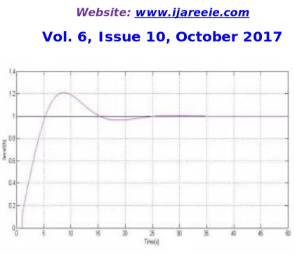
Autotuning Control Based PID Implementation For CSTH Process- The control and simulation (while) loop used in this program is related to the practical control loop is shown in the block diagram Figure (6). The set point=30cm is given and the controller to stops when the set point reaches. When the DAQ Output (0-5) V, I-P Converter (3-15) PSI, V-I Converter (4-20)mA Control Valve 30 set point is reached, 5V is generated in the analog output indicator. For the corresponding level upto the set point reaches the corresponding intermediate temperature as well as voltages values are displayed in the Front panel. When the set point is reached, the SCR which in turn stops the heating of water into the tank.
Fig.6 Block Diagram for Autotuning Control Based PID Implementation for CSTH Process
V. RESULT AND DISCUSSION
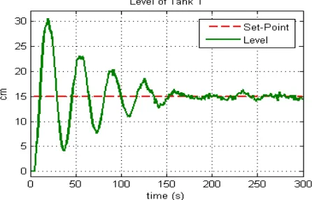
For Temperature control process Set Point=45oC and the corresponding time the set points reaches is shown in the Figure (7) where Kp=28.21, Ki=4.12, Kd=47.89.
Vol. 6, Issue 10, October 2017
Fig.8 Autotuned PID Controller for Time Vs Level
For Temperature control process Set Point=45oC and the corresponding time the set points reaches is shown in the figure. In autotuning control tuning when the set point reaches PID controller stops at exact set point.
VI.CONCLUSION
The simulation and real time experimental results shows the autotuning self-tuning algorithm provides the better output response for the CSTH process when compare to conventional Ziegler Nicholas and Cohen-coon tuning methods. The proposed algorithm progresses the performance of the controller, based on set point tracking and reduces the peak overshoot and delay time. From the simulation results it is observed that the automatic gain scheduling of controller parameters are updated within limited period of time. That the performance of the CSTH process has improved and the parameters are sustained at their preferred level of set points with minimum Integral Square Error (ISE), rise time, peak over shoot & settling time.
REFERENCES
[1] Nina F. Thornhill, Sachin C. Patwardhan, Sirish L. Shah. (2008) “A continuous stirred tank heater simulation model with applications” Journal of Process Control, Elsevier.
[2] B. Wayne Bequette (2004) “Process control Modeling Design and Simulation” PHI.
[3] MohammadSoroush Soheilirad,Maryam Mohd. Isa,Mojgan Hojabri and Samsul Bahari Mohd. Noor. (2012) “Modeling Simulation and Control of a Laboratory Scale Continues Stirred Tank Heater” Journal of Basic and Applied Scientific Research 2(5),pp.5362-5373.
[4] Ali Rabiee, Hooshang Jazayeri-Rad and Mohamad Ali Takassi.(2013) “Nonlinear Model Predictive Control of a Continuous Stirred Tank Heater based on Multiple Neural Networks” Journal of Basic and Applied Scientific Research 3(4),pp.893-900.
[5] Kalpesh B. Pathak, Dipak M. Adhyaru. (2012) “ Survey of Model Reference Adaptive Control” IEEE International Conference NUiCONE. [6] Girish Chowdhary and Eric N. Johnson. (2007) “Adaptive Neural Network Flight Control Using both Current and Recorded Data” AIAA
Guidance, Navigation and Control Conference and Exhibit, Hilton Head, South Carolina.
[7] Shengquan Li,Juan Li,Jinhao Qiu,Hongli Ji and KongJun Zhu. (2011) “Control design for arbitrary complex nonlinear discrete-time system based on direct NNMRAC strategy” Journal of Process Control, Elsevier.
[8] Karl Johan Astrom. (2001) “Auto Tuning” 2nd Ed, Pearson Education.
[9] M.S. Ahmed. (2000) “Neural net based MRAC for a class of nonlinear plants” Neural Networks 13, contributed article, Elsevier,pp.111-124. [10] Dipak M.Adhyaru, (2012) “State Observer Design For Nonlinear Systems using Neural Network Based HJB formulation”, Applied Soft