961 |
P a g e
SOLAR TRACKING SYSTEM USING PISTON
Dr.K.Chitra
1, M. Archana
2, D.Deepa
3, R.Sowntharya
4 1Assistant Professor (Senior Grade), EEE Department, Bannari Amman Institute of Technology
2,3,4
Final year students, EEE Department, Bannari Amman Institute of Technology
ABSTRACT
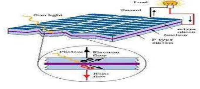
A solar cell is an electronic device which directly converts sunlight into electricity. Light shining on the solar cell produces both a current and a voltage to generate electric power. This process requires firstly, a material in which the absorption of light raises an electron to a higher energy state, and secondly, the movement of this higher energy electron from the solar cell into an external circuit. The electron then dissipates its energy in the external circuit and returns to the solar cell. A variety of materials and processes can potentially satisfy the requirements for photovoltaic energy conversion, but in practice nearly all photovoltaic energy conversion uses semiconductor materials in the form of a p-n junction. With regard to the development of sustainable energy, such as solar energy, in this article we will Study types of solar cells and their applications.
I. INTRODUCTION
Every day, the sun radiates (sends out) an enormous amount of energy called solar energy. It radiates more energy in one day than the world uses in one year. This energy comes from within the sun itself. Like most stars, the sun is a big gas ball made up mostly of hydrogen and helium gas. The sun makes energy in its inner core in a process called nuclear fusion.
It takes the sun’s energy just a little over eight minutes to travel the 93 million miles to Earth. Solar energy
travels at the speed of light, or 186,000 miles per second, or 3.0 x 10⁸ meters per second.Only a small part of the visible radiant energy (light) that thesun emits into space ever reaches the Earth, but that is more than enough to supply all our energy needs. Every hour enough solar energy reaches the Earth to supply our nation’s
energy needs for a year! Solar energy is considered a renewable energy source due to this fact.
Today, people use solar energy to heat buildings and water and to generate electricity. Solar energy accounts for a very small percentage of U.S. energy less than one percent.Solar energy is mostly used by residences and to generate electricity.Solar Collectors Heating with solar energy is not as easy as you might think. Capturing sunlight and putting it to work is difficult because the solar energy that reaches the Earth is spread out over a large area.
The sun does not deliver that much energy to any one place at any one time. The amount of solar energy an area receives depends on the time of day, the season of the year, the cloudiness of the sky, and how close you are to the Earth’s Equator.
A solar collector is one way to capture sunlight and change it into usable heat energy. A closed car on a sunny day is like a solar collector.As sunlight passes through the car’s windows, it is absorbed by the seat covers,
walls, and floor of the car. The absorbed light changes into heat.
The car’s windows let light in, but they don’t let all the heat out. A closed car can get very hot Solar Space
962 |
P a g e
Today, many homes use solar energy for space heating. A passive solar home is designed to let in as much sunlight as possible.It is like a big solar collector Sunlight passes through the windows and heats the walls and floor inside the house. The light can get in, but the heat is trapped inside. A passive solar home does not depend on mechanical equipment, such as pumps and blowers, to heat the house, whereas active solar homes do.An active solar home, on the other hand, uses special equipment to collect sunlight. An active solar house may use special collectors that look like boxes covered with glass.These collectors are mounted on the rooftop facing south to take advantage of the winter sun. Dark-colored metal plates inside the boxes absorb sunlight and change it into heat. (Black absorbs sunlight better than any other colour).
II. SOLAR TRACKING
A Rockwell Automation White Paper Solar Trackers Are Devices Used To Orient Photovoltaic Panels, Reflectors, Lenses Or Other Optical Devices Toward The Sun. Since The Sun’s Position In The Sky Changes
With The Seasons And The Time Of Day, Trackers Are Used To Align The Collection System To Maximize Energy Production. Several Factors Must Be Considered When Determining The Use Of Trackers. Some Of These Include: The Solar Technology Being Used, The Amount Of Direct Solar Irradiation, Feed-In Tariffs In The Region Where The System Is Deployed, And The Cost To Install And Maintain The Trackers.
Concentrated Applications Like Concentrated Photovoltaic Panels (CPV) Or Concentrated Solar Power (CSP) Require A High Degree Of Accuracy To Ensure The Sunlight Is Directed Precisely At The Focal Point Of The Reflector Or Lens. Non-Concentrating Applications Don’t Require Tracking But Using A Tracker Can Improve The Total Power Produced By The System. Photovoltaic Systems Using High Efficiency Panels With Trackers Can Be Very Effective. There Are Many Types Of Solar Trackers, Of Varying Costs, Sophistication, And Performance. The Two Basic Categories Of Trackers Are Single Axis And Dual Axis.
2.1 Single Axis Solar Tracking
Single axis Solar trackers can either have a horizontal or a vertical axis. The horizontal type is used in tropical regions where the sun gets very high at noon, but the days are short. The vertical type is used in high latitudes where the sun does not get very high, but summer days can be very long. In concentrated solar power applications, single axis trackers are used with parabolic and linear Fresnel mirror designs. Single Axis Trackers Single axis trackers have one degree of freedom that acts as an axis of rotation. The axis of rotation of single david publishing Comparison of Solar Trackers and Application of Sensor Less Dual Axis Solar Tracker 557 axis trackers is typically aligned along a true north meridian. It is possible to align them in any cardinal direction with advanced tracking algorithms. There are several common implementations of single axis trackers. These include HSAT (horizontal single axis trackers), VSAT (vertical single axis trackers), TSAT (tilted single axis trackers) and PSAT (polar aligned single axis trackers). The orientation of the module with respect to the tracker axis is important when modeling performance. Al-Mohammad designed a single axis sun-tracking system. Two symmetric photo-resistors are used to track the sun’s position. A PLC (programmable logic unit) is employed to control and monitor the mechanical movement of the PV module and collect and store data related to the sun’s
963 |
P a g e
connected to a personal computer through the RS232 serial port to monitor the whole process on a computer screen. Abdallah and Badran designed a single axis sun-tracking system for enhancing solar still productivity. A computerized sun tracking device is used for rotating the solar still with the movement of the sun. In this study, the programming method of control works efficiently in all weather conditions regardless of the presence of clouds. The calculated values of the surface positions as a function of time are fed to the PLC program to control the actuator of the sun position tracker, 24 V AC electrical motor. A comparison between fixed and sun tracked solar stills shows that the use of sun tracking increased the productivity for around 22%, due to the increase of overall efficiency by 2%. It can be concluded that, the sun tracking is more effective than fixed system and it is capable of enhancing the productivity. Sefa, designed a one axis solar tracking system. A DC motor with 24 V, 50 W is used for the movement of the solar panel in east or west directions. All movement procedures are controlled using two photo resistors. The tracking system includes a serial communication interface based on RS485 to monitor whole processes on a computer screen and to plot data as graphic. In addition, system parameters such as the current, the voltage and the panel position have been observed by means of a microcontroller. The energy collected is measured and compared with a fixed solar system for the same solar panel. The results show that, the solar energy collected on the tracking system is considerably much efficient than the fixed system. Al-Haddad and Hassan designed a one axis solar tracking system. The control part of the system is made using electronic circuit that have the op-amp LM324 as the main component. While for the mechanical part, the moving base of the reflector of the satellite receiver antenna is used. Measurements have been made for comparison between fixed and tracking system. The results have shown that, the tracking system is effective in the sense of relatively high output power increase and low cost. Agarwal and Pal designed a computer based one axis solar tracking system. LDR is used as photo sensor to sense the incident solar radiation. A computer based stepper motor is used in the tracking system to provide motion to the photovoltaic panel. The results show that, in cloudy weather, the system cannot track the actual position of the actual position of the sun, because of the absence of shading effect.2.2 Dual Axis Solar Tracking
Dual axis Solar trackers have both a horizontal and a vertical axis and thus they can track the sun's apparent motion virtually anywhere in the world. CSP applications using dual axis tracking include solar power towers and dish (Stirling engine) systems. Dual axis tracking is extremely important in solar tower applications due to the angle errors resulting from longer distances between the mirror and the central receiver located in the tower structure. Many traditional solar PV applications employ two axis trackers to position the solar panels perpendicular to the sun’s rays. This maximizes the total power output by keeping the panels in direct sunlight
964 |
P a g e
compared with those fixed at a surface tilted 32° towards south. Preliminary measurements indicated that, the use of two axis sun tracking would increase daily energy collection by more than 40%. Roth, designed a two axis sun tracking system. The tracker gives the possibility for automatic measuring of direct solar radiation with a pyrheliometer. In the active operation mode, the tracker uses the signal of a sun detecting linear sensor to control the pointing. Two stepper motors move the instrument platform, keeping the sun’s beam at the center ofthe sensor. Hassan, designed a two axis sun tracking system. The system is sensorless and open loop controlled. A wiper motor has been used for azimuth tracking and a linear actuator has been used for declination tracking. Tested results shows that a significant increase of the efficiency of the tracker. Duarte, designed a two axis sun tracking system. This work studies the solution of two axis solar tracking system based on solar maps, which can predict the exact apparent position of the sun, by the latitude’s location, thereby avoiding the need to use
sensors or guidance systems.
2.3 Circuit Diagram
Figure 1.Circuit Diagram For Solar Tracking Using Piston
III. SOLAR PANEL
3.1 Solar Energy
One of the most important problems facing the world today is the energy problem.This problem is resulted from the increase of demand for electrical energy and high cost of fuel. Solar energy is the term used for the heat and light which the sunlight contains. Sunlight reaches to earth in the form of photons. Photons are energy packets that contain light in it. Solar energy is considered as a renewable energy source because it does not destroy our eco system and is present naturally in the environment.
965 |
P a g e
Place the set up in dark
When the two LDRs are in dark, there is no movement in the panel.
Now place a torch in front of the left LDR. Panels slowly move towards its left.
Now move light from left to right. You can observe the panel moving slowly with the torch towards right.
In the middle, when intensity on both LDRs is equal, panel will not move until there is difference between the light intensity falling on the LDRs.
Advantages of Sun Tracking Solar Panel
1.The solar energy can be reused as it is non renewable resource. 2.This also saves money as there is no need to pay for energy used.
Sun Tracking Solar Panel Applications
1.These panels can be used to power the traffic lights and streetlights 2.These can be used in home to power the appliances using solar power.
3.These can be used in industries as more energy can be saved by rotating the panel.
Limitations of Sun Tracking Solar Panel Circuit
1.Though solar energy can be utilized to maximum extent this may create problems in rainy season
.
2.Although solar energy can be saved to batteries, they are heavy and occupy more space and required to change time to time.
3.They are expensive
.
3.2 Photo Voltaic Cells
Photovoltaic (PV) system is well recognized and widely utilized to convert the solar energy for electric power applications. It can generate direct current (DC) electricity without environmental impact and emission by way of solar radiation. The DC power is converted to AC power with an inverter, to power local loads or fed back to the utility. Being a semiconductor device, the PV systems are suitable for most operation at a lower maintenance costs.
Figure 2.Photo Voltaic Cells
966 |
P a g e
The same principle as using a magnifying lens to focus the Sun's rays on a pile of kindling or paper to start fires. Solar concentrators put one of these lenses over every solar cell. This technology allows costs to be cut significantly due to the utilization of less material.3.3 Solar Panel
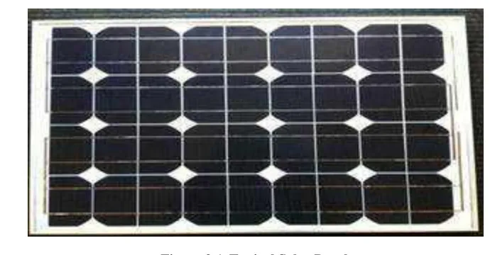
Figure 3.A Typical Solar Panel.
A solar panel is a set of solar photovoltaic modules electrically connected and mounted on a supporting structure. A photovoltaic module is a packaged, connected assembly of solar cells. The solar module can be used as a component of a larger photovoltaic system to generate and supply electricity in commercial and residential applications. Each module is rated by its DC output power under standard test Condit Solar modules use light energy (photons) from the sun to generate electricity through the photovoltaic effect. The majority of modules use wafer-based crystalline silicon cells or thin-film cells based on cadmium telluride or silicon. The structural (load carrying) member of a module can either be the top layer or the back layer. Cells must also be protected from mechanical damage and moisture. Most solar modules are rigid, but semi-flexible ones are available, based
on thin-film cells
.
3.4 Types of Solar Panel
The types of solar panels are monocrystalline,polycrystalline,hybridand black frame panels
.
3.4.1 Monocrystalline Silicon Solar Panels
The Solar cells made of monocrystalline silicon (mono-Si), also called single-crystalline silicon (single-crystal-Si), are quite easily recognizable by anexternal even coloring and uniform look, indicating high-purity silicon, as you can see on the picture below:Monocrystalline solar cells are made out of silicon ingots, which are cylindrical in shape. To optimize performance and lower costs of a single monocrystalline solar cell, four sides are cut out of the cylindrical ingots to make silicon wafers, which is what gives monocrystalline solar panels their characteristic look.A good way to separate mono- and polycrystalline solar panels is that polycrystalline solar cells look perfectly rectangular with no rounded edges.
967 |
P a g e
● Monocrystalline solar panels have the highest efficiency rates since they are made out of the highest-grade silicon. The efficiency rates of monocrystalline solar panels are typically 15-20%. SunPower produces the highest efficiency solar panels on the U.S. market today. Their E20 series provide panel conversion efficiencies of up to 20.1%.Update (April, 2013): SunPower has now released the X-series at a record-breaking efficiency of 21.5%.● Monocrystalline silicon solar panels are space-efficient. Since these solar panels yield the highest power outputs, they also require the least amount of space compared to any other types. Monocrystalline solar panels produce up to four times the amount of electricity as thin-film solar panels.
● Monocrystalline solar panels live the longest. Most solar panel manufacturers put a 25-year warranty on their monocrystalline solar panels.
● Tend to perform better than similarly rated polycrystalline solar panels at low-light conditions.
Disadvantages
● Monocrystalline solar panels are the most expensive. From a financial standpoint, a solar panel that is made of polycrystalline silicon (and in some cases thin-film) can be a better choice for some homeowners.
● If the solar panel is partially covered with shade, dirt or snow, the entire circuit can break down. Consider getting micro-inverters instead of central string inverters if you think coverage will be a problem. Micro-inverters will make sure that not the entire solar array is affected by shading issues with only one of the solar panels.
● The Czochralski process is used to produce monocrystalline silicon. It results in large cylindrical ingots. Four sides are cut out of the ingots to make silicon wafers. A significant amount of the original silicon ends up as waste.
● Monocrystalline solar panels tend to be more efficient in warm weather. Performance suffers as temperature goes up, but less so than polycrystalline solar panels. For most homeowners temperature is not a concern.
3.4.2 POLYCRYSTALLINE SILICON SOLAR PANELS
The first solar panels based on polycrystalline silicon, which also is known as polysilicon (p-Si) and multi-crystalline silicon (mc-Si), were introduced to the market in 1981. Unlike monomulti-crystalline-based solar panels, polycrystalline solar panels do not require the Czochralski process. Raw silicon is melted and poured into a square mold, which is cooled and cut into perfectly square wafers.
Advantages
● The process used to make polycrystalline silicon is simpler and cost less. The amount of waste silicon is less compared to monocrystalline.
968 |
P a g e
Disadvantages
● The efficiency of polycrystalline-based solar panels is typically 13-16%. Because of lower silicon purity, polycrystalline solar panels are not quite as efficient as monocrystalline solar panels.
● Lower space-efficiency. You generally need to cover a larger surface to output the same electrical power as you would with a solar panel made of monocrystalline silicon. However, this does not mean every
monocrystalline solar panel perform better than those based on polycrystalline silicon. Monocrystalline and thin-film solar panels tend to be more aesthetically pleasing since they have a more uniform look compared to the speckled blue color of polycrystalline silicon.
3.4.3 Biohybrid Solar Panel
A biohybrid solar cell is a solar cell made using a combination of organic matter (photosystem I) and inorganic matter. Biohybrid solar cells have been made by a team of researchers at Vanderbilt University. The team used the photosystem I (a photoactive protein complex located in the thylakoid membrane) to recreate the natural process of photosynthesis to obtain a greater efficiency in solar energy conversion. These biohybrid solar cells are a new type of renewable energy.[3][4] Multiple layers of photosystem I gather photonic energy, convert it into chemical energy and create a current that goes through the cell. The cell itself consists of many of the same non-organic materials that are found in other solar cells with the exception of the injected photosystem I complexes which are introduced and gathered for several days in the gold layer. After days the photosytem I are made visible and appear as a thin green film. It is this thin film that helps and improves the energy conversion. The biohybrid cell however, is still in the research phase.The team from Vanderbilt University began conducting research on the photosynthesis when they began to see and focus on the photosystem I protein. After seeing how widely available and efficient the protein was at solar conversion they began to look to incorporate and improve different technologies. The team used spinach as their source for the photosystem I. Thylakoid membranes were isolated and then went into a purification process to separate the photosystem I from the thylakoid membrane. Their research resulted in a greatly improved electrical current (1000 times greater) compared to those previous made by other solar cells. The team has been gathering a group of undergraduate engineers to help build the first prototype of the biohybrid solar cell. The team has also come up with a second design of the protein complex the photosystem
3.5 Types Of Solar Trackers
There are many different types of solar tracker which can be grouped into single axis and dual axis.
3.5.1 Single Axis Trackers
969 |
P a g e
The axis of rotation of single axis trackers is typically aligned along a true North meridian. It is possible to align them in any cardinal direction with advanced Single axis trackers have one degree of freedom that acts as an axis of rotation tracking algorithms. There are several common implementations of single axis trackers. These include horizontal single axis trackers (HSAT), vertical single axis trackers (VSAT), tilted single axis trackers (TSAT) and polar aligned single axis trackers (PSAT). The orientation of the module withrespect to the trackeraxis is important when modeling performance
.
3.5.2 Dual Axis Trackers
Dual axis trackers have two degrees of freedom that act as axes of rotation. These axes are typically normal to one another. The axis that is fixed with respect to the ground can be considered a primary axis. The axis that is referenced to the primary axis can be considered a secondary axis.
Figure 5. Dual Axis Tracker.
There are several common implementations of dual axis trackers. They are classified by the orientation of their primary axes with respect to the ground. Two common implementations are tip-tilt dual axis trackers (TTDAT) and azimuth-altitude dual axis trackers (AADAT).The orientation of the module with respect to the tracker axis is important when modeling performance. Dual axis trackers typically have modules oriented parallel to the secondary axis of rotation. Dual axis trackers allow for optimum solar energy levels due to their ability to follow the sun vertically and horizontally. No matter where the sun is in the sky, dual axis trackers are able to angle themselves to be in direct contact with the sun.
3.6 Light Dependent Resistor
The dominant of street lights, outside lights, a number of indoor home appliances, and so on are typically operated and maintained manually on many occasions. This is not only risky, however additionally leads to wastage of power with the negligence of personnel or uncommon circumstances in controlling these electrical appliances ON and OFF. Hence, we can utilize the light sensor circuit for automatic switch OFF the loads based on daylight’s intensity by employing a light sensor. This article discusses in brief about what is a light
970 |
P a g e
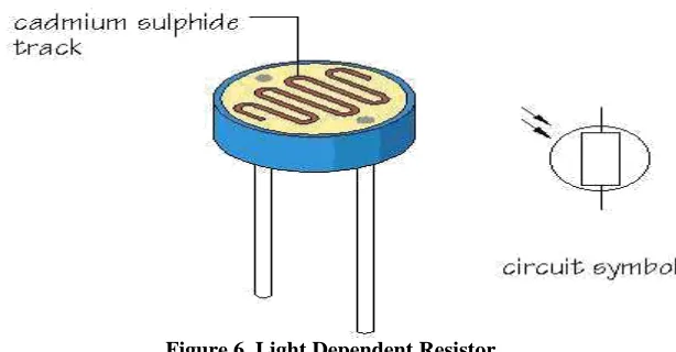
Figure 6. Light Dependent Resistor
An LDR or light dependent resistor is also known ass photo resistor, photocell, photoconducto r.It is a one type of resistor whose resistance varies depending on the amount of light falling on its surface. When the light falls on the resistor, then the resistance changes. These resistors are often used in many circuits where it is requir ed to sense the presence of light. These resistors have a variety of functions and r esistance. For instance, when the LD R is in darkness, then it can be used to tu rn ON a light or to turn OFF a light when it is in the light. A typical light dependent resistor has a resistance in the darkness of 1MOhm, and in the brightness a resistance of a couple of KOhm.
3.6.1 Working Principle of LDR
This resistor work s on the principle of photo conductiv ity. It is nothing but, when the light falls on its surface, then the material cond uctivity reduces and also the electrons i n the valence band of the device ar e excited to the conduction band. These photons in the incident light must have energy greater than the band gap of the semiconductor material.This makes the electrons to jump from the valence band to conduction.These devices dep end on the light, when light falls on the LDR then the resistance decreases, and increases in the dark.When a LDR is kept in the dark place, its resistance is high and, when the LDR is kept in the light its resistance will decrease.If a constant “V’ is applied to the LDR, the intensity of the light increased and current increases. The
figure below shows the curve between resistance Vs illumination curve for a particular light dependent resistor.
3.6.2 Light Dependent Resistor Applications
Light dependent resistors have a low cost and simple structure. These resistors are frequently used as light sensors. These resistors are mainly used when there is a need to sense the absence and presence of the light such as burglar alarm circuits, alarm clock, light intensity meters, etc. LDR resistors mainly involves in various electrical and electronic projects. For better understanding of this concept, here we are explaining some real
time projects where the LDR resistors are used
.
3.7 Lead Acid Storage Battery
971 |
P a g e
During charging of battery, current is passed through it which causes some chemical changes inside the battery. This chemical changes absorb energy during their formation.When the battery is connected to the external load, the chemical changes take place in reverse direction, during which the absorbed energy is released as electrical energy and supplied to the load.Now we will try to unde rstand principle working of lead acid battery and for that we will first discuss about lead acid batterywhich is very co mmonly used as storage battery or second ary battery.
Figure 7.Lead Acid Storage Battery
3.7.1 Materials Used For Lead Acid Storage Battery Cells
The main active materials required to construct a lead acid battery are
1. Lead peroxide ( PbO2). 2. Sponge lead (Pb)
3. Dilute sulfuric acid (H2SO4).
3.8 Auto Valve
The control valve can be either a manual one or an auto matic one. With a manual control valve, if you want the pool water to be heated up and the sun is out, then you 'll have to turn the handle on the valve yourself to get the water to flow t o the solar collectors. Then, at night, you'll have to manually turn the handle again to stop the water from flowing to the collectors otherwise your hot pool water will flow through the now cool collectors,
give its heat to the collectors and then go back into the pool as now cooler water
.
3.9 Air Piston
972 |
P a g e
To operate a piston you need to connect the storage container to a piston through a valve. The valve either stops or allows air flow based on some control. When the valve is opened, the pressure from the storage container pushes on the inside of the piston, causing it to extend. This force can be used to do useful work at high speed. During use, the storage stage should ideally be maintained at a higher pressure than the operation stage. The greater the positive difference is between the storage pressure and operation pressure, the more air you have left to work with before pressure in your system begins to drop.The design goal for this system is to ensure that safe storage can be achieved for pressures around 120 psi while doing operations at around 60 psi for the operation stage. For the size of the robots that are used in PiE, it is inadvisable to run the operation stage higher than 60 psi (per advice of Elton and Douglas).IV.RELAY
The relay is an automatic protective and switching device which is capable of sensing abnormal conditions in electrical circuits. These are operated to open or close the load contacts in response to one or more electrical quantities like voltage and current. Relays are used in a wide variety of applications like electric power systems, home appliances, automobiles, industrial equipments, digital computers, etc.Relays are classified into several types based on their functionality and application they are implemented for. These classifications include electromagnetic, solid state, high voltage, thermal relays, and so on. Therefore, this document is intended to describe about a few basic types of relays that are popularly used in typical load-control applications.This document explains each and every relay and its working principle with appropriate figures. Only some of the relays are explained in this document for making it simple and understandable. Hope that you will get a good idea on this topic once you start reading this information. Furthermore, for any help or information on this topic or implementing these relays practically in electrical circuits you can comment below.
We know that most of the high end industrial application devices have relays for their effective working. Relays are simple switches which are operated both electrically and mechanically. Relays consist of a n electromagnet and also a set of contacts. The switching mechanism is carried out with the help of the electromagnet. There are also other operating principles for its working. But they differ according to their applications. Most of the devices have the application of relays.
The main operation of a relay comes in places where only a low-power signal can be used to control a circuit. It is also used in places where only one signal can be used to control a lot of circuits. The application of relays started during the invention of telephones. They played an important role in switching calls in telephone exchanges. They were also used in long distance telegraphy. They were used to switch the signal coming from one source to another destination. After the invention of computers they were also used to perform Boolean and other logical operations. The high end applications of relays require high power to be driven by electric motors and so on. Such relays are called contactors.
4.1 Relay Design
There are only four main parts in a relay. They are
Electromagnet
973 |
P a g e
Switch point contacts
Spring
Figure 9. Design Of A Simple Relay
4.2. Relay Construction
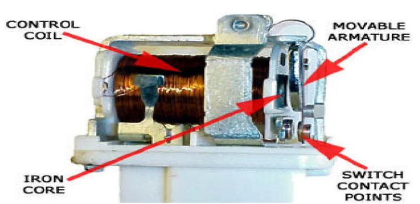
It is an electro-magnetic relay with a wire coil, surrounded by an iron core. A path of very low reluctance for the magnetic flux is provided for the movable armature and also the switch point contacts. The movable armature is connected to the yoke which is mechanically connected to the switch point contacts. These parts are safely held with the help of a spring. The spring is used so as to produce an air gap in the circuit when the relay becomes de-energized.
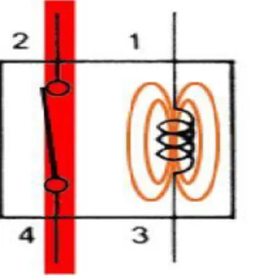
4.3 Working
The working of a relay can be better understood by explaining the following diagram given below.The diagram shows an inner section diagram of a relay. An iron core is surrounded by a control coil. As shown, the power source is given to the electromagnet through a control switch and through contacts to the load. When current starts flowing through the control coil, the electromagnet starts energizing and thus intensifies the magnetic field. Thus the upper contact arm starts to be attracted to the lower fixed arm and thus closes the contacts causing a short circuit for the power to the load. On the other hand, if the relay was already de-energized when the contacts were closed, then the contact move oppositely and make an open circuit.As soon as the coil current is off, the movable armature will be returned by a force back to its initial position. This force will be almost equal to half the strength of the magnetic force. This force is mainly provided by two factors. They are the spring and also gravity.
974 |
P a g e
.Figure 10.Working Of Relay
4.4 Relay Basics
The basics for all the relays are the same. Take a look at a 4 – pin relay shown below. There are two colours shown. The green colour represents the control circuit and the red colour represents the load circuit. A small control coil is connected onto the control circuit. A switch is connected to the load. This switch is controlled by the coil in the control circuit. Now let us take the different steps that occour in a relay.
975 |
P a g e
4.5 Energized Relay (ON)
As shown in the circuit, the current flowing through the coils represented by pins 1 and 3 causes a magnetic field to be aroused. This magnetic field causes the closing of the pins 2 and 4. Thus the switch plays an important role in the relay working. As it is a part of the load circuit, it is used to control an electrical circuit that is connected to it. Thus, when the relay in energized he current flow will be through the pins 2 and 4.
Figure 12.Energized Relay (On)
De – Energized Relay (OFF)
As soon as the current flow stops through pins 1 and 3, the switch opens and thus the open circuit prevents the current flow through pins 2 and 4. Thus the relay becomes de-energized and thus in off position.
976 |
P a g e
4.5 Pole and Throw
Relays have the exact working of a switch. So, the same concept is also applied. A relay is said to switch one or more poles. Each pole has contacts that can be thrown in mainly three ways. They are
Normally Open Contact (NO) – NO contact is also called a make contact. It closes the circuit when the relay is activated. It disconnects the circuit when the relay is inactive.
Normally Closed Contact (NC) – NC contact is also known as break contact. This is opposite to the NO contact. When the relay is activated, the circuit disconnects. When the relay is deactivated, the circuit connects.
Change-over (CO) / Double-throw (DT) Contacts – This type of contacts are used to control two types of circuits. They are used to control a NO contact and also a NC contact with a common terminal. According to their type they are called by the names break before make and make before breakcontacts.
Relays are also named with designations like
Single Pole Single Throw (SPST) – This type of relay has a total of four terminals. Out of these two terminals can be connected or disconnected. The other two terminals are needed for the coil.
Single Pole Double Throw (SPDT) – This type of a relay has a total of five terminals. Out f these two are
the coil terminals. A common terminal is also included which connects to either of two others.
Double Pole Single Throw (DPST) – This relay has a total of six terminals. These terminals are further divided into two pairs. Thus they can act as two SPST’s which are actuated by a single coil. Out of the six
terminals two of them are coil terminals
.
Double Pole Double Throw (DPDT) – This is the biggest of all. It has mainly eight relay terminals. Out of these two rows are designed to be change over terminals. They are designed to act as two SPDT relays which are actuated by a single coil.
Relay Applications
Relays are used to realize logic functions. They play a very important role in providing safety critical logic.
Relays are used to provide time delay functions. They are used to time the delay open and delay close of contacts.
Relays are used to control high voltage circuits with the help of low voltage signals. Similarly they are used to control high current circuits with the help of low current signals.
They are also used as protective relays. By this function all the faults during transmission and reception can be detected and isolated.
4.6 Relay Selection
You must note some factors while selecting a particular relay. They are
Protection – Different protections like contact protection and coil protection must be noted. Contact protection helps in reducing arcing in circuits using inductors. Coil protection helps in reducing surge voltage produced during switching.
Look for a standard relay with all regulatory approvals.
977 |
P a g e
Ratings – There are current as well as voltage ratings. The current ratings vary from a few amperes to about 3000 amperes. In case of voltage ratings, they vary from 300 Volt AC to 600 Volt AC. There are also high voltage relays of about 15,000 Volts.
Type of contact used – Whether it is a NC or NO or closed contact.
Select Make before Break or Break before Make contacts wisely.
Isolation between coil circuit and contacts
V. TRANSISTORS
A transistor is a device that regulates current or voltage flow and acts as a switch or gate for electronic signals. Transistors consist of three layers of a semiconductor material, each capable of carrying a current.The transistor was invented by three scientists at the Bell Laboratories in 1947, and it rapidly replaced the vacuum tube as an electronic signal regulator. A transistor regulates currentor voltage flow and acts as a switch or gate for electronic signals. A transistor consists of three layers of a semiconductor material, each capable of carrying a current. A semiconductor is a material such as germanium and silicon that conducts electricity in a "semi-enthusiastic" way. It's somewhere between a real conductor such as copper and an insulator (like the plastic wrapped around wires).The semiconductor material is given special properties by a chemical process called
doping. The doping results in a material that either adds extra electrons to the material (which is then called N-type for the extra negative charge carriers) or creates "holes" in the material's crystal structure (which is then called P-typebecause it results in more positive charge carriers). The transistor's three-layer structure contains an N-type semiconductor layer sandwiched between P-type layers (a PNP configuration) or a P-type layer between N-type layers (an NPN configuration).A small change in the current or voltage at the inner semiconductor layer (which acts as the control electrode) produces a large, rapid change in the current passing through the entire component. The component can thus act as a switch, opening and closing an electronic gate many times per second. Today's computers use circuitry made with complementary metal oxide semiconductor (CMOS) technology. CMOS uses two complementary transistors per gate (one with N-type material; the other with P-type material). When one transistor is maintaining a logic state, it requires almost no power.Transistors are the basic elements in integrated circuits (IC), which consist of very large numbers of transistors interconnected with
circuitry and baked into a single silicon microchip
.
5.1 Working of transistor
A transistor is a miniature electronic component that can do two different jobs. It can work either as an amplifier or a switch:
978 |
P a g e
explained transistor-amplifiers to a student in a more humorous way: "If you take a bale of hay and tie it to the tail of a mule and then strike a match and set the bale of hay on fire, and if you then compare the energy expended shortly thereafter by the mule with the energy expended by yourself in the striking of the match, you will understand the concept of amplification." Transistors can also work as switches. A tiny electric current flowing through one part of a transistor can make a much bigger current flow through another part of it. In other words, the small current switches on the larger one. This is essentially how all computer chips work. For example, a memory chip contains hundreds of millions or even billions of transistors, each of which can be switched on or off individually. Since each transistor can be in two distinct states, it can store two different numbers, zero and one. With billions of transistors, a chip can store billions of zeros and ones, and almost as many ordinary numbers and letters
VI. MICROCONTROLLER
Even at a time when Intel presented the first microprocessor with the 4004 there was alrady a demand for microcontrollers: The contemporary TMS1802 from Texas Instruments, designed for usage in calculators, was by the end of 1971 advertised for applications in cash registers, watches and measuring instruments. The TMS 1000, which was introduced in 1974, already included RAM, ROM, and I/O on-chip and can be seen as one of the first microcontrollers, even though it was called a microcomputer. The first controllers to gain really widespread use were the Intel 8048, which was integrated into PC keyboards, and its successor, the Intel 8051, as well as the 68HCxx series of microcontrollers from Motorola.
Today, microcontroller production counts are in the billions per year, and the controllers are integrated into many appliances we have grown used to, like household appliances (microwave, washing machine, coffee machine)
telecommunication (mobile phones)
automotive industry (fuel injection, ABS, . . . )
aerospace industry
industrial automation
But what is this microcontroller we are talking about? What is the difference to a microprocessor? And why do we need microcontrollers in the first place? To answer these questions, let us consider a simple toy project: A heat control system. Assume that we want to periodically read the temperature (analog value, is digitized by sensor; uses 4-bit interface),
control heating according to the temperature (turn heater on/off; 1 bit),
display the current temperature on a simple 3-digit numeric display (8+3 bits),
allow the user to adjust temperature thresholds (buttons; 4 bits), and
be able to configure/upgrade the system over a serial interface.
979 |
P a g e
VII. POWER
The Power Management Unit (PMU) is a microcontroller that governs power functions of digital platforms. This microchip has many similar components to the average computer, including firmware and software, memory, a CPU, input/output functions, timers to measure intervals of time, and analog to digital converters to measure the voltages of the main battery or power source of the computer. The PMU is one of the few items to remain active even when the computer is completely shut down, powered by the backup
battery.
For portable computers, the PMU is responsible for coordinating many functions, including:
Monitoring power connections and battery charges
Charging batteries when necessary
Controlling power to other integrated circuits
Shutting down unnecessary system components when they are left idle
Controlling sleep and power functions (on and off)
Managing the interface for built in keypad and trackpads on portable computers
Regulating the real-time clock (RTC)
Resetting the PMU in these circumstances can be a relatively quick and easy fix to some of these issues. There is a keyboard shortcut on newer Apple laptops with an internal battery, nicknamed "SCOP". This stands for Shift Control Option Power. This "reboots" the PMU software in order to get it working as it should. For Apple laptops with a removable battery, resetting the PMU involves unplugging the power adapter, disconnecting the battery, then holding down the power button for five seconds. Another PMU-related fix would be to reset the logic board, where one removes the backup battery on the board for a few minutes, then reinstalls it, causing the PMU to reset itself with clean, fresh parameters (that need to be corrected, if desired, to its previous state) during the next Mac OS boot (for typical PC users, this is similar to "resetting the CMOS").
The PMU is very sensitive and a reset may be necessary if a backup battery dies. Even plugging in one's laptop in the wrong order can cause issues (power into the outlet first, THEN power to the computer). Never turn off an attached UPS without first unplugging the AC adapter.
Memory types in microcontrollers Architecture
The microcontrollers units (MCUs) consists of three types of memory. 1. Program Memory
2. Data Memory 3. Data EEPOM
Program Memory type
This is common which have all the microcontroller and its purposes is to store the instructions.it consist of further four different types of memory.
1. ROM (Read only memory)
2. EPROM (Erasable programmable read only memory) 3. OTP (On time programmable)
980 |
P a g e
Data Memory
This is also a common in all the microcontrollers. Its consist of general purposes registers referred to as GPR and special function registers referred to as SPR. The data memory is divide into 4 banks and each banks having a length 128 bytes. For access to each bank the bits PR1 and PR0 of status register needs to be accessed. The special function register controls the various aspects of microcontroller depend upon the process architecture of microcontroller. It controls the following functions of controller such as input, output and peripheral control, Timer, program counter, stack pointer, stack limit, condition codes and processor status. The general purpose registers store the transient type data. For example, when the program is interrupted in its state then that value of address register, instruction register or program counter is saved in general purpose register.
Data EEPROM Memory
In addition of program and data memory some of the microcontrollers have third type of that is called data EEPROM . This is nonvolatile its data can be written in many times.
VIII. CONCLUSION
The solar tracking system has been designed and implemented. It tends to use the maximum amount of solar energy by effective tracking.
Economical, compact and efficient system of solar energy conversion had been made possible with this design.
REFERENCES
[1.] C. Alexandru, C. Pozna, 2010 "Different tracking strategies for optimizing the energetic efficiency of a photovoltaic system”, The IEEE International Conference on Automation, Quality and Testing, Robotics. [2.] Carlos Andrés Giraldo-Castañeda and Lionel R. Orama-Exclusa, 2008 “Selective Hopping Maximum
Power Point Tracking Method for PV systems”, The IEEE International Conference on Sustainable