Atlas AVM JR.
Legal Notice
Key System US provides this document "as is," with no representations or warranties, either explicit or implied, including but not limited to the implied warranties of merchantability, title, or fitness for a particular purpose.Key System US reserves the right to make changes in product software, hardware, or documentation at any time, with no obligation to inform any persons or entities of such changes. Every attempt has been made to ensure the accuracy of this document. However, Key System US assumes no
responsibility for any losses, whether electronic, financial, or other, that might accrue from inadvertent inaccuracies that the software or documentation might contain.
Some states or jurisdictions do not allow disclaimer of explicit or implicit warranties in certain situations. Therefore, this statement might not apply to you.
Copyright © 2000. Key System US. All rights under copyright reserved. The AVM JR. engine is covered by patent pending and copyright protection.
The contents of this document may not be duplicated by any means, whether electronic, graphic, or mechanical, including, but not limited to, photocopying, recording, taping, or information recording and retrieval systems, for any purpose but the original purchaser's personal use, without prior written permission of Key System US.
Trademark Information
AVM JR., Key System US, and Atlas IIE are trademarks of KS Telecom Inc. All other trademarks are the property of their respective owners.
Software Version
Atlas AVM JR. Installation and Programming Manual III
Table Of Contents
Table Of Contents ... III
1. INTRODUCTION ...1-1
1.1 FEATURES AND SERVICES...1-2 1.1.1 System Features...1-2 1.1.2 Automated Attendant Features ...1-3 1.1.3 Voice Mail Features ...1-5 1.2 ABOUT THIS MANUAL...1-7
2. DESCRIPTION AND INSTALLATION ...2-1
2.1 BASE SYSTEM...2-2 2.2 PHYSICAL DESCRIPTION...2-2 2.2.1 Side Panel...2-3 2.2.2 Front Panel...2-3 2.3 INSTALLATION...2-4 2.3.1 Unpacking ...2-4 2.3.2 Installing the AVM JR. ...2-5 2.3.3 Expanding the System...2-7 2.4 SPECIFICATIONS...2-10
3. DTMF PROGRAMMING...3-1
3.8.5 Playing a System Message...3-29 3.8.6 Listening to the Software Version Number ...3-29 3.8.7 Listening to the System Time and Date...3-29 3.8.8 Resetting the System ...3-30 3.8.9 Adjusting Recording Length ...3-30
4. PROGRAMMING BY COMPUTER...4-1
4.1 CONNECTING THE COMPUTER TO THE AVM JR. ...4-1 4.2 SYSTEM REQUIREMENTS...4-2 4.3 INSTALLING THE VUP ...4-3 4.4 STARTING VUP ...4-3 4.5 DEFINING THE AVM JR. PARAMETERS...4-5 4.5.1 Defining PBX Parameters ...4-5 4.5.2 Defining System Parameters ...4-9 4.6 PROGRAMMING THE VOICE MAIL...4-11 4.6.1 Viewing the Mailbox List...4-11 4.6.2 Creating Mailboxes ...4-12 4.6.3 Changing the Parameters of an Existing Mailbox ...4-14 4.6.4 Deleting an Existing Mailbox ...4-15 4.6.5 Organizing Mailbox Groups...4-15 4.6.6 Setting Notification Parameters ...4-17 4.7 PROGRAMMING THE AUTOMATED ATTENDANT...4-18 4.7.1 To program a script message ...4-18 4.7.2 Setting Up Different Script Menus Per Port...4-20 4.8 SETTING THE TIME, DATE AND OPERATION MODE...4-22 4.8.1 Setting up Auto Mode ...4-23 4.9 WORKING WITH CONFIGURATION FILES...4-26 4.10 DOWNLOADING DATA TO THE AVM JR. ...4-26 4.11 VIEWING STATISTICAL INFORMATION STORED IN THE AVM JR. DATABASE...4-27 4.12 PRINTING REPORTS...4-27 4.13 SAVING REPORTS...4-28 4.14 GETTING HELP...4-28 4.15 CLOSING THE VUP ...4-28
5. USER OPERATING INSTRUCTIONS ...5-1
Atlas AVM JR. Installation and Programming Manual V 5.4.7 Return to Previous Menu...5-6 5.5 SEND MESSAGE...5-6 5.6 RETURN TO AUTO ATTENDANT...5-6 5.7 QUICK REFERENCE GUIDE...5-7
6. TROUBLESHOOTING...6-1
7. APPENDIX A ...7-1
8. APPENDIX B...8-1
9. APPENDIX C ...9-1
10. APPENDIX D ...10-1
SMDR E ...10-1 SMDR-64/256 ...10-2 SMDR-U (KDX-500)...10-3
11. APPENDIX E...11-1
E.1 KSX-32/64/128/256 DETAILED PROGRAMMING...11-1 E.1.1 Programming Voicemail Ports ...11-1 E.1.2 Programming the Station Group ...11-1 E.1.3 Programming Direct Ring ...11-2 E.1.4 Programming Delayed Ringing...11-3 E.2 KDX-500 DETAILED PROGRAMMING...11-4 E.2.1 Programming Voicemail Ports ...11-4 E.2.2 Programming the Station Hunt Group ...11-4 E.2.3 Programming Direct Ringing...11-5 E.2.4 Programming Delayed Ringing...11-6
Table of Figures
Atlas AVM JR. Installation and Programming Manual 1-1 The AVM JR. is a small stand-alone Voice Mail/Automated Attendant system for organizations that have between eight and eighty employees. Developed by KS Telecom, a leader in the field of Telephone Equipment and Voice Processing Systems. The AVM JR. incorporates state of the art technology, including DSP, flash memory and SMT production.
Figure 1-1 General View
The AVM JR. is available in two or four port versions. It features 128 mailboxes and provides from 2 hours and 40 minutes to up to 8 hours recording time.
The AVM JR. is designed to be integrated with all Key System US KSU's through single line ports for voice and using the RS-232 serial port for SMDI integration.
Installing the AVM JR. is quick and easy. Just mount it on a wall next to the KSU and connect it to the single line ports, the SMDR serial port, and the main power supply with an external power adapter.
The AVM JR's voice mail system is ready for use immediately after the system administrator completes a short procedure that includes setting up mailboxes, notification type, system schedules and opening greetings. Each mailbox owner can then set up his own personal mailbox parameters.
1.1
1.1
Features and Services
Features and Services
The AVM JR. is a powerful voice mail system at an affordable price. It contains most of the useful features and services provided by PC-based systems but at a lower cost. The JR's features can be divided into three groups:
• System
• Automated Attendant • Voice Mail
1.1.1 System Features
• Configuration
The AVM JR. comes with two ports and two hours and forty minutes of recording time. The system administrator can upgrade the AVM JR. by: − Adding a two port expansion card to the motherboard to provide four ports − Inserting a memory card with two hours and forty minutes of storage space
to increase the total storage capacity to five hours and twenty minutes − Inserting a memory card with five hours and twenty minutes of storage
space to increase the total storage capacity to eight hours • Programming
Atlas AVM JR. Installation and Programming Manual 1-3 • Integration with your PBX
− The AVM JR. integrates with the KSU through the SMDR RS-232 port using SMDI signaling
• Message Notification
The AVM JR. automatically notifies the mailbox owner of new messages in different ways according to the system configuration. Notification may be local (to an extension) or remote (to a telephone at a remote location, a cellular telephone or a pager).
• Security Passwords
The AVM JR. supports three types of passwords, each with four digits: − System Administrator. Gives access to all data stored in the AVM JR.. − Operator. Gives access to the operating modes.
− Mailbox. Gives access to individual mailboxes. The mailbox owner can change the password any time.
1.1.2 Automated Attendant Features
The AVM JR.’s automated attendant answers incoming calls and, through a series of recorded menus and telephone directories, helps the callers reach the desired extensions.
• Opening Greeting
The AVM JR. plays a pre-recorded greeting to callers. The opening greeting usually includes the organization’s name, how to reach an extension,
department or operator, how to leave a message and how to access a directory. During the greeting, callers can access a department by dialing a single digit, dialing the extension number or holding for assistance.
• Operating Modes
− Day Mode
During normal business hours, the AVM JR. answers calls with a pre-recorded daytime greeting. The daytime greeting enables the caller to reach a requested extension, mailbox, department, directory or operator. − Night Mode
During non-working hours, the AVM JR. answers calls with a pre-recorded nighttime greeting that enables the caller to leave a message in a requested mailbox.
− Holiday Mode
During holidays, the AVM JR. answers calls with a special greeting that enables the caller to leave a message in a specific mailbox or in the operator’s mailbox. The holiday mode can be activated by the operator (password protected).
− Break Mode
The system administrator can program part of the day mode as break time. During break time, the AVM JR. answers calls with a special greeting that enables the caller to leave a message in a specific mailbox or in the operator’s mailbox.
• System Schedules (Auto-Mode)
If your organization has operating hours that vary from day to day, the system administrator can define the daily operating schedules on a weekly basis, including daytime, nighttime and break time hours. When the Auto mode is activated, the AVM JR. automatically switches between the day, night and break modes according to your pre-defined schedule.
The operator can override the pre-defined system schedule and switch manually to day, night, break, or holiday mode using a password. • Fax Detection
Atlas AVM JR. Installation and Programming Manual 1-5 • Directory
The system administrator can set up a directory containing the names and extensions of all the organization’s employees. A caller can access this directory by following instructions during the opening greeting. • Call Transfer
The system administrator can program the AVM JR. to detect the Call Progress tones sent by the KSU and transfer the calls to extensions in one of the following modes:
− Non-Supervised. The AVM JR. transfers the call immediately without verifying the status of the extension.
− Supervised. The AVM JR. checks for a busy or answer signal before transferring the call to the extension.
− Semi-Supervised. The AVM JR. only checks for a busy signal before transferring the call to the extension.
• Answering on the First Ring
To avoid delays, the system administrator can set up the AVM JR. on each individual port to answer incoming calls on the first ring.
• Script Menus
The AVM JR. supports up to 25 script menus. A script menu is a recorded announcement that can accept a digit entry (0-9) during playback. Based on the digit entered, the AVM JR. can take one of the following actions: − Transfer the call to another script menu
− Transfer the call to an extension or hunt group − Transfer the call to a mailbox or a mailbox group − Retrieve messages from a mailbox
− Disconnect the line
1.1.3 Voice Mail Features
• Real/Virtual Mailboxes
The AVM JR. supports up to 128 real and/or virtual mailboxes. A real mailbox is associated with a telephone extension. A virtual mailbox is not associated with a telephone extension.
• Personalized Mailboxes
Each mailbox owner can personalize his mailbox by recording a personal greeting, assigning a personal password to the mailbox and setting optional parameters.
• Personal Greeting
Each mailbox owner can record or change his personal greeting at any time from any touch-tone telephone. Callers first hear the personal greeting of the called extension and then can leave a message.
• Day and Time Stamp
The system administrator can program the AVM JR. to indicate at the start of each message the day and time the message was recorded.
• Message Deletion
A mailbox owner can manually delete messages or the system administrator can program the AVM JR. to automatically delete all messages after a specific number of days.
• Message Redirection
A mailbox owner can forward a copy of a message to another mailbox or mailbox group. The mailbox owner can also record an introduction to the forwarded message.
• Mailbox Groups
Atlas AVM JR. Installation and Programming Manual 1-7
1.2
1.2
About this Manual
About this Manual
This manual presents information needed to install, program and maintain the AVM JR., Version 4.xx. It is divided into the following sections:
1. INTRODUCTION
Introduces the AVM JR. and lists its features. 2. DESCRIPTION AND INSTALLATION
Provides a functional description of the AVM JR., installation instructions and specifications.
3. DTMF PROGRAMMING
Describes how to program the AVM JR. from any DTMF or system telephone. 4. PROGRAMMING BY COMPUTER
Describes how to program the AVM JR. using the Voicemail Utility Program. 5. USER OPERATING INSTRUCTIONS
Explains how to program and use a mailbox. 6. TROUBLESHOOTING
Presents answers to commonly asked questions on operating the AVM JR.. APPENDIX A
Summarizes the programming commands. APPENDIX B
Contains the DTMF programming forms. APPENDIX C
Lists the system messages APPENDIX D
Shows SMDR connections and DIP switch settings APPENDIX E
Atlas AVM JR. Installation and Programming Manual 2-1 The AVM JR. is a digital system consisting of a:
• Sophisticated DSP voice-processing device
• Flash memory for voice recording and storing KSU parameter information • Central Processing Unit
• Two or four audio channels • Real-time clock
The AVM JR. provides two major services: • Automated Attendant Service
Uses predefined menus to direct calls to a specific department, extension or mailbox.
• Voice Mail Service
Receives and delivers messages. Each mailbox has its own number and the mailbox owner has a password to enable him to access his mailbox.
Messages can be saved, deleted or transferred to other mailboxes. In one step, the mailbox owner can also send an identical message to a group of mailboxes or to all the mailboxes in the system.
You can customize the AVM JR.’s Automated Attendant and Voice Mail systems to suit the needs of your company. You can configure:
• KSU parameters, such as hook flash time.
• Automated Attendant script menus and customized “Busy”, “No Answer” and “Do Not Disturb” menus.
2.1
2.1
Base System
Base System
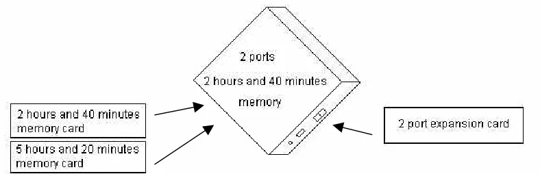
The AVM JR. comes with two lines and two hours and forty minutes of recording time.
You can upgrade the AVM JR. by:
• Adding a two line expansion card to the motherboard to provide four lines • Inserting a memory card with two hours and forty minutes of storage space to
increase the total storage capacity to five hours and twenty minutes
• Inserting a memory card with five hours and twenty minutes of storage space to increase the total storage capacity to eight hours
Note: You may only install one memory expansion card per system.
Figure 2-1 Options for Upgrading the Base System
2.2
2.2
Physical Description
Physical Description
Atlas AVM JR. Installation and Programming Manual 2-3
2.2.1 Side Panel
Figure 2-2 Side Panel
The numbered items in the following description correspond to the labels in Figure 2-2.
1. Power Supply Connector Connects the AVM JR. to the external power supply
2. RS-232 Connector Connects the AVM JR. to the Key System or a PC
3. 2 RJ-11 Sockets Connects the AVM JR. to 2 or 4 Key System extensions
2.2.2 Front Panel
The following table describes the function of the four LED's on the front panel.
STATUS DAY NIGHT HOLIDAY AUTO
Day Mode: Manual On Off Off Off
Night Mode: Manual Off On Off Off
Holiday Mode: Manual Off Off On Off
Day Mode: Auto On Off Off On
Night Mode: Auto Off On Off On
Break Mode: Auto On On Off On
System Error1 Off Flashing Off Off
System Error1 Flashing Flashing Flashing Flashing System Error1 Flashing Flashing Flashing Off
Automatic Self-Test On On On On
1
Please contact technical support.
2.3
2.3
Installation
Installation
The AVM JR. is delivered completely assembled. It is designed for mounting on a wall close to the KSU.
2.3.1 Unpacking
Before unpacking, inspect the package. If you notice any damage, immediately report it to technical support.
ä
To unpack the AVM JR.:
1. Place the package on a flat surface and open it.
Atlas AVM JR. Installation and Programming Manual 2-5
2.3.2 Installing the AVM JR.
ä
To install the AVM JR.:
1. Mount the unit on a wall close to the KSU by using the drill template to place the two screws.
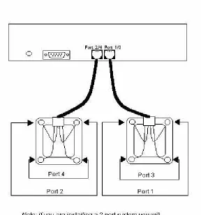
2. Connect the RJ-11 connector on one end of the cables to the RJ-11 sockets on the side panel of the AVM JR.. Connect the other end of the cables to one or two analog telephone lines on the Main Distribution Frame (MDF) of the KSU (see Figure 2-4).
Note: Each RJ-11 socket on the side panel of the AVM JR. can support up to two single line extensions.
4. On the side of the AVM JR., plug the 9V DC adapter jack into the power supply connector.
5. Plug the 9V DC adapter into the main power supply outlet to turn the AVM JR. on. The LED's on the front panel turn on and off one after another and then the LED indicating the status of the AVM JR. turns on. 6. Connect one end of the RS-232 cable to the AVM JR.’s RS-232
connector and the other end to the RS-232 connector of the SMDR. - If you are using an SMDR-E unit, you should plug the RS-232 cable
into the port labeled COM 2 on the SMDR.
- If you are using an SMDR-256/64 unit, you should plug the RS-232 cable into the port labeled J1, the lower of the DB-25 connectors on the card. To do this you will have to use the supplied DB-9 to DB-25 converter.
- If you are using an SMDRU (KDX-500) unit you should plug the RS-232 cable into the port labeled CN10 (Com 3)
Note: If you are attaching a caller id unit or InnFone call accounting system to the SMDR along with the voicemail you must remove pin 3 from the DB-9 connector that attaches to the SMDR RS-232 port. However, please contact technical support before doing this to verify your application.
- Refer to APPENDIX D for cabling diagrams 7. Set your dip switch settings on the SMDR
- If you are using an SMDR-E you should turn switch one (1) on and have six (6) off. The rest do not affect the voicemail interface - If you are using an SMDR-256/64 you should turn switch one (1) on
and have three (3) and six (6) off. The rest do not affect the voicemail interface.
Atlas AVM JR. Installation and Programming Manual 2-7 10. Program the analog station ports you are using as voicemail ports in the
KSU. Refer to APPENDIX E for programming procedures for your particular system as they vary between systems.
11. Program the voicemail ports into a station hunt group. Refer to APPENDIX E for programming procedures for your particular system as they vary between systems.
12. Program the voicemail to ring for incoming calls, either delayed or direct. Refer to APPENDIX E for programming procedures for your particular system as they vary between systems.
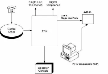
Figure 2-5 System Installation
2.3.3 Expanding the System
2.3.3.1 Expanding to Four Lines
The two-port expansion kit contains: • 2-port expansion card
• 4-wire connector • Two plastic stand-offs
ä
To install the expansion card:
1. Disconnect all external cables and connectors.
2. Remove the 9V DC adapter power plug from the main power supply outlet to turn the AVM JR. off.
3. Open the AVM JR.’s top cover by unscrewing the four screws. 4. Place the two plastic stand-offs into the corresponding holes. 5. Insert the expansion card into the corresponding J6 connector. 6. Connect one end of the 4-wire cable to J5 on the motherboard and the
other end to J5 on the expansion card.
7. Replace the top panel cover and plug the 9V DC adapter into the main power supply outlet to turn the AVM JR. on.
8. Reconnect all the external cables and connectors to the AVM JR..
9. Connect your two new analog ports to the corresponding connectors on the AVM JR.
10. Program your two new ports as voicemail ports. Refer to APPENDIX E for programming procedures for your particular system as they vary between systems.
11. Program your two new ports in your voicemail station hunt group. Refer to APPENDIX E for programming procedures for your particular system as they vary between systems.
Atlas AVM JR. Installation and Programming Manual 2-9 • Five hours and twenty minutes card with 4 memory chips
ä
To install the memory expansion card:
1. Disconnect all external cables and connectors.
2. Remove the 9V DC adapter power plug from the main power supply outlet to turn the AVM JR. off.
3. Open the AVM JR.’s top cover by unscrewing the four screws. 4. Insert the memory card into the SIMM connector.
5. Replace the top panel cover and plug the 9V DC adapter into the main power supply outlet to turn the AVM JR. on.
6. Reconnect all the external cables and connectors to the AVM JR..
AVM JR. automatically detects memory size when it is turned on.
2.4
2.4
Specifications
Specifications
DC Power Supply 9V DC/800 mA
Line Voltage 24V to 72V DC
DC Leakage Current < 10 µA
On-hook Insulation Resistance between Line Terminal and
the Ground
0V to 100V DC > 5 MΩ 100V to 200V DC > 30 KΩ 500V AC/50 Hz > 20 KΩ 100V AC/25 Hz > 100 KΩ
Ring Capacitor 0.47 µF ± 10%
On-hook Impedance @ 50V DC, 40V AC/25 Hz > 3000 Ω
Ring Detect 27V to 100V AC/16 to 60 Hz
DC Resistance (off-hook) 24V to 66V DC @ 20 to 100 mA 100 to 350 Ω
Impedance (off-hook) 300 to 3400 Hz 500 to 700 Ω
Imbalance Ratio 300 to 3400 Hz > 46 db
Return Loss 300 to 3400 Hz > 18 db
Current during Break < 700 µA
DTMF Transmission: Frequency Tolerance
Frequency Level (High Group) Frequency Level (Low Group)
+1.5% -6 to -8 dBm -8 to -10 dBm
Inter-digit Pause in Tone Dialing 70 to 80 ms
Atlas AVM JR. Installation and Programming Manual 3-1
3. DTMF PROGRAMMING
You can program the AVM JR. by: • Telephone using DTMF tones
• Computer using the Voicemail Utility Program (see Section 4)
This section describes programming the AVM JR. using DTMF tones.
Note: You will hear a confirmation tone every time you enter a programming command.
3.1
3.1
Entering and
Entering and Exiting the Programming Mode
Exiting the Programming Mode
The AVM JR. does not handle calls when in the programming mode.
ä
To enter the programming mode:
1. Connect a single line extension to the AVM JR.. (This should have been done during the installation)
2. Call the single line extension from any other extension on the system. 3. Wait until the AVM JR. answers and plays the opening menu. Then dial
*900.
Note: If you are calling from a system extension that has a mailbox set up for it you will first have to dial the mailbox password and then from the mailbox menu dial “9” to get to the main greeting. You can then dial “*900”
4. Dial the System Administrator’s password (the default password is 1234) to enter the programming mode.
ä
To exit the programming mode:
• Dial *900. –or–
Note: If you exited the programming mode by dialing *900, the AVM JR. plays the opening menu. You can then test the changes made to the system.
3.2
3.2
First Time Programming Checklist
First Time Programming Checklist
1. Call from a system extension to the AVM JR.. You will hear the default message (system message 000 - see Appendix C).
2. Dial *900 and the administrator password (default: 1234) to enter the programming mode.
3. Set the KSU parameters (see Sections 3.3 and 6) to ensure the proper operation of the AVM JR. with your KSU.
Note: These parameters are set by the factory for a 2-digit system all flash times and message light parameters should not have to be changed.
4. Set the AVM JR’s real-time clock (see Section 3.4). 5. Set the system schedule (see Section 3.5).
6. Create mailboxes (see Section 3.6.1).
7. Define a notification type for each mailbox (see Section 3.6.3).
8. Define notification parameters (i.e., message light on and message light off and interval between ring notification in Section 3.6.3.) Message light parameters are set from the factory.
9. Record (see Section 3.7.1) and program (see Section 3.7.2) script menus for the Automated Attendant. Make sure you define the mailboxes before building Automated Attendant script menus.
Important: Make sure you record the Day Opening script (script 00)
before using the AVM JR. for the first time
.3.3
3.3
Defining KSU Parameters
Defining KSU Parameters
Atlas AVM JR. Installation and Programming Manual 3-3 Table 3-1 PBX Parameter Commands
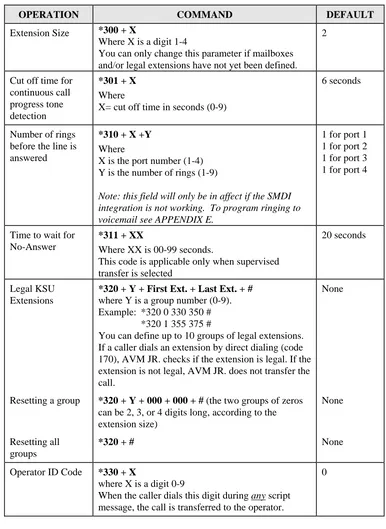
OPERATION COMMAND DEFAULT
Extension Size *300 + X
Where X is a digit 1-4
You can only change this parameter if mailboxes and/or legal extensions have not yet been defined.
2
Cut off time for continuous call progress tone detection
*301 + X
Where
X= cut off time in seconds (0-9)
6 seconds
Number of rings before the line is answered
*310 + X +Y
Where
X is the port number (1-4) Y is the number of rings (1-9)
Note: this field will only be in affect if the SMDI integration is not working. To program ringing to voicemail see APPENDIX E.
1 for port 1 1 for port 2 1 for port 3 1 for port 4
Time to wait for No-Answer
*311 + XX
Where XX is 00-99 seconds.
This code is applicable only when supervised transfer is selected
20 seconds
Legal KSU Extensions
*320 + Y + First Ext. + Last Ext. + #
where Y is a group number (0-9). Example: *320 0 330 350 # *320 1 355 375 #
You can define up to 10 groups of legal extensions. If a caller dials an extension by direct dialing (code 170), AVM JR. checks if the extension is legal. If the extension is not legal, AVM JR. does not transfer the call.
None
Resetting a group *320 + Y + 000 + 000 + # (the two groups of zeros can be 2, 3, or 4 digits long, according to the extension size)
None
Resetting all groups
*320 + # None
Operator ID Code *330 + X
where X is a digit 0-9
When the caller dials this digit during any script message, the call is transferred to the operator.
OPERATION COMMAND DEFAULT
Programmable code for retrieving messages
*331 + X
Where X is a digit 0-9
When the caller dials this digit at the no answer or busy greeting for their mailbox the system will prompt them for their password
9
Disconnect Code *333 + Code1 + #
The AVM JR terminates the call when it receives the disconnect code. The code can include up to four digits. Legal values for this code can be any combination of 0-9, *, # and A-D
###
Clear Disconnect Code
*333 + #
External Access Code
*340 + X
where X is the external access code (0-9). This code is applicable for external notification.
9
Clear External Access Code
*340 + #
Pause before and after external access code
*341 + X
Where X is the length of the pause in seconds (0-9)
2 seconds
Transfer mode for all extensions
*350 + X + Y
X = 1; All Extensions except the operator X = 2; Operator extension only
Y = 0; Non Supervised Y = 1; Supervised Mode Y = 2; Semi Supervised Mode
Atlas AVM JR. Installation and Programming Manual 3-5
OPERATION COMMAND DEFAULT
Day Operator, Night Operator, Fax and Supervisor’s Extension numbers
*360 + X + YYYY + #
where:
X = 1; Day operator X = 2; Night operator X = 3; Fax extension X = 4; Supervisor extension
One mailbox can be defined as Supervisor. When the storage memory reaches 80% of its capacity, a message is sent to this mailbox indicating the situation.
YYYY = Corresponding extension number
0 0 - - Delete the extension assignments
*360 + X + #
Where:
X = 1; Day operator X = 2; Night operator X = 3; Fax extension X = 4; Supervisor extension
Volume level *369 + X
Where:
X = volume level (0-9), 9 = Loudest
5
Flash-1 *370 + XXX
where XXX is a 3-digit number (000-980) in increments of 20 ms.
Example: *370 300 sets Flash-1 to 300 ms
600 ms
Flash-2 Flash-2 is fixed at 1200 ms.
Flash-2 is used in some KSU’s for Recall from No-Answer or Busy Codes.
1200 ms
Busy, Disconnect and DTMF Off/On time
*371 + X + YYY
where:
X = 1; busy off (100-980 ms) X = 2; busy on (100-980 ms) X = 3; disconnect off (100-980 ms) X = 4; disconnect on (100-980 ms) X = *; DTMF off (000-980 ms) X = #; DTMF on (000-980 ms)
OPERATION COMMAND DEFAULT
Busy Signal Cadence Check
*375 + XXXX + #
Where XXXX is a busy extension number. Checks the busy signal by dialing the busy extension number and playing the busy cadence values.
Voice and DTMF Sensitivity
*376 + X + Y
X = 1; Voice sensitivity level X = 2; DTMF sensitivity level Y = Sensitivity level (0-9)
The volume at which the AVM JR detects voice when the called extension answers or the volume level at which the unit detects DTMF throughout it’s operation.
Note: The higher the sensitivity level, the higher the sensitivity to voice or DTMF.
In order to activate the new selection, a new call must be initiated
5 5
Automatic Gain Control (AGC)
*377 + X
X = 0 AGC disabled X = 1 AGC enabled
When enabled, AVM JR will adjust the incoming messages volume to a set volume level.
In order to activate the new selection, a new call must be initiated
Enabled
DTMF amplitude *379 + X
Where X = volume level (0-9), 9 = Loudest
5
Procedural codes sent to the PBX in order to perform a specific task
*380 + X + CODE1 + #
X = 1; LED 1 notification code X = 2; LED 2 notification code X = 3; LED notification off code X = 4; Transfer code
X = 5; Recall from Busy X = 6; Recall from No Answer
Atlas AVM JR. Installation and Programming Manual 3-7
OPERATION COMMAND DEFAULT
Delete a specific procedural code
*380 + X + #
X = 1; LED 1 notification code X = 2; LED 2 notification code X = 3; LED notification off code X = 4; Transfer code
X = 5; Recall from Busy X = 6; Recall from No Answer
Answer number of samples
*386 + X
Where:
X = number of samples (0-9)
5
1
Refers to Key System codes. Each code contains digits 0-9, *, #, Flash-1, Flash-2, Pause and Extension Number.
Note: The PBX codes for Message Light On and Message Light Off can also include A-D.
When entering a code, dial: *0 for extension *1 for pause *2 for Flash-1 *3 for Flash-2 *4 for #
3.4
3.4
Setting the Time and Date
Setting the Time and Date
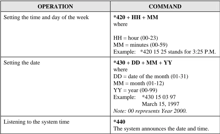
Table 3-2 presents commands used to set the AVM JR. clock and calendar.
Table 3-2 Commands to Set the AVM JR. Clock and Calendar
OPERATION COMMAND
Setting the time and day of the week *420 + HH + MM
where
HH = hour (00-23) MM = minutes (00-59)
Example: *420 15 25 stands for 3:25 P.M.
Setting the date *430 + DD + MM + YY
where
DD = date of the month (01-31) MM = month (01-12)
YY = year (00-99) Example: *430 15 03 97 March 15, 1997 Note: 00 represents Year 2000.
Listening to the system time *440
The system announces the date and time.
3.5
3.5
Programming the Operational Mode
Programming the Operational Mode
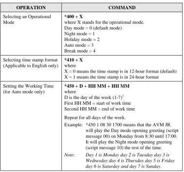
Atlas AVM JR. Installation and Programming Manual 3-9 Table 3-3 Programming the Operational Modes
OPERATION COMMAND
Selecting an Operational Mode
*400 + X
where X stands for the operational mode. Day mode = 0 (default mode)
Night mode = 1 Holiday mode = 2 Auto mode = 3 Break mode = 4
Selecting time stamp format (Applicable to English only)
*410 + X
where
X = 0 means the time stamp is in 12-hour format (default) X = 1 means the time stamp is in 24-hour format
Setting the Working Time (for Auto mode only)
*450 + D + HH MM + HH MM
where
D is the day of the week (1-7)1 First HH MM = start of work time Second HH MM = end of work time
Repeat for all days of the week.
Example: *450 1 08 30 1700 means that the AVM JR. will play the Day mode opening greeting (script message 00) on Monday from 8:30 until 17:00. It will play the Night mode opening greeting (script message 10) the rest of the time. Note: Day 1 is Monday day 2 is Tuesday day 3 is
OPERATION COMMAND
Setting the Break Time (for Auto mode only)
*460 + D + HH MM + HH MM
where
D is the day of the week (1-7)1 First HH MM = start of break time Second HH MM = end of break time
Repeat for all days of the week.
Example 1: *460 1 13 15 14 30
AVM JR. will play the Break mode opening greeting (script message 15) on Monday, from 13:15 until 14:30.
Note: Day 1 is Monday day 2 is Tuesday day 3 is Wednesday day 4 is Thursday day 5 is Friday day 6 is Saturday and day 7 is Sunday.
Entering annual holiday dates
(For Auto mode only)
*470 + DD + MM + hh:mm + hh:mm
Where:
DD = Day of month (01-31) MM = Month (01-12)
Hh:mm = Start time; Hour and minutes in 24 hour format Hh:mm = End time; Hour and minutes in 24 hour format Repeat for multiple days
Example 1: *470 02 12 08 15 23 45
The AVM JR will play the Holiday mode opening greeting on December 2nd, from 8:15 until 11:45.
Delete all holidays on a specific date
*470 + DD + MM #
Where:
DD = Day of month (01-31) MM = month (01-12)
Delete all holidays on a specific month
*470 + ** + MM + #
Where:
MM = month (01-12)
Atlas AVM JR. Installation and Programming Manual 3-11
OPERATION COMMAND
External Notification Active Time
*490 + hh:mm + hh:mm
Where:
hh:mm = Start time; Hour and minutes in 24 hour format
hh:mm = End Time; Hour and minutes in 24 hour format Example 1: *490 09 00 20 00
AVM JR will activate the external notification between 9 am to 8 pm.
3.6
3.6
Programming the Voice Mail
Programming the Voice Mail
3.6.1 Creating Mailboxes
You can define up to 128 mailboxes. The mailbox number and its extension number are identical. Make sure that the number of digits in the mailbox number conforms to the number of digits in an extension (*300).
You can also create a virtual mailbox for a user who does not have an extension. When a caller dials a virtual mailbox number on the Automated Attendant menu, the call is immediately transferred to the Do Not Disturb menu and the caller is given the option to leave a message.
You may use the external notification features for the virtual mailboxes. Do not select internal notification because virtual mailboxes do not have extensions to light message waiting lights on.
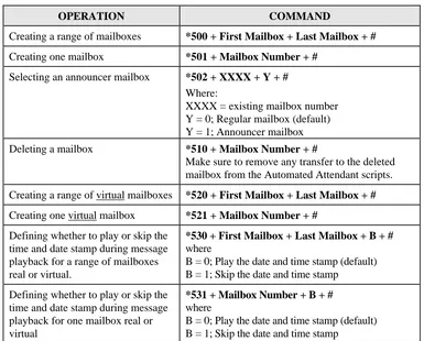
Table 3-4 Commands to Create Mailboxes
OPERATION COMMAND
Creating a range of mailboxes *500 + First Mailbox + Last Mailbox + #
Creating one mailbox *501 + Mailbox Number + #
Selecting an announcer mailbox *502 + XXXX + Y + #
Where:
XXXX = existing mailbox number Y = 0; Regular mailbox (default) Y = 1; Announcer mailbox
Deleting a mailbox *510 + Mailbox Number + #
Make sure to remove any transfer to the deleted mailbox from the Automated Attendant scripts.
Creating a range of virtual mailboxes *520 + First Mailbox + Last Mailbox + #
Creating one virtual mailbox *521 + Mailbox Number + #
Defining whether to play or skip the time and date stamp during message playback for a range of mailboxes real or virtual.
*530 + First Mailbox + Last Mailbox + B + #
where
B = 0; Play the date and time stamp (default) B = 1; Skip the date and time stamp
Defining whether to play or skip the time and date stamp during message playback for one mailbox real or virtual
*531 + Mailbox Number + B + #
where
B = 0; Play the date and time stamp (default) B = 1; Skip the date and time stamp
3.6.2 Creating Mailbox Groups
You can create up to four mailbox groups for distributing messages. Each mailbox group can contain up to twenty mailboxes. The group numbers are by default 000, 001, 002 and 003. Group 099 consists of all mailboxes (real and virtual).
Atlas AVM JR. Installation and Programming Manual 3-13 Table 3-5 Commands to Create Mailbox Groups
OPERATION COMMAND
Adding a mailbox to a group *540 + Group Number + Mailbox Number + #
Note: You must define the mailbox before adding it to a group.
Changing the number of the first digit in the mailbox groups
*545 + X
where X is the first digit of the mailbox groups. Default is 0.
Deleting a mailbox from a group *550 + Group Number + Mailbox Number + #
Resetting a group *560 + Group Number + #
Note: Resetting a group deletes all the mailboxes within that group.
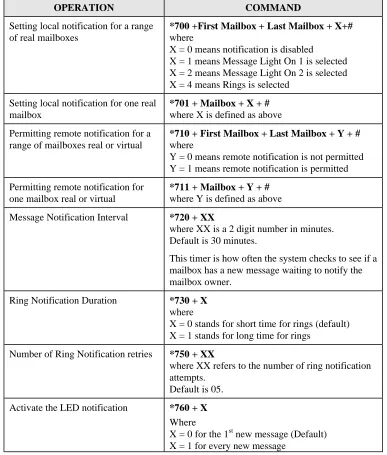
3.6.3 Notification
AVM JR. notifies the mailbox owner of new messages in different ways according to the system configuration. Notification may be local or remote.
Notification is always done on port two.
Local Notification
You can select one of the following options: • None. The notification feature is disabled.
• Message Light On. The AVM JR. signals the Key System that a mailbox has received the first message. The Key System then turns on the message light of the telephone extension. If the Message Light Off code is programmed, the code is sent to the KSU after the mailbox owner retrieves all his new messages.
Remote Notification
The mailbox owner may choose to be notified at a remote location (i.e., his mobile or home telephone number) by entering a remote telephone number of up to 20 digits. You can use any combination of *, #, A-D, 0-9, and Pause (*1) when setting the remote notification telephone number.
After remote notification is enabled, the AVM JR. will dial the remote telephone number and notify the mailbox owner of any new messages. After entering the password, the mailbox owner can retrieve his messages. The duration of remote notification rings is programmed using code *730.
The AVM JR. stops sending Ring notifications after the mailbox owner retrieves all his new messages or the maximum number of retries has been made (code *750). The mailbox owner must obtain permission from the System Administrator to enable remote notification. The System Administrator must use code *710 or *711 to grant permission.
When permission has been granted and the mailbox owner enables remote notification, the AVM JR. first dials the external access digit (programmed using code *340) and then dials the mailbox owner’s remote telephone number.
Note: Make sure that you enter the remote telephone number before enabling remote notification.
Notification is always done on port two.
3.6.3.1 Setting Notification for Mailboxes
Notes:
1. Virtual mailboxes do not have extensions and may not be configured for internal notification.
Atlas AVM JR. Installation and Programming Manual 3-15 Table 3-6 Commands to Program Notification for Mailboxes
OPERATION COMMAND
Setting local notification for a range of real mailboxes
*700 +First Mailbox + Last Mailbox + X+# where
X = 0 means notification is disabled
X = 1 means Message Light On 1 is selected X = 2 means Message Light On 2 is selected X = 4 means Rings is selected
Setting local notification for one real mailbox
*701 + Mailbox + X + # where X is defined as above
Permitting remote notification for a range of mailboxes real or virtual
*710 + First Mailbox + Last Mailbox + Y + #
where
Y = 0 means remote notification is not permitted Y = 1 means remote notification is permitted
Permitting remote notification for one mailbox real or virtual
*711 + Mailbox + Y + # where Y is defined as above
Message Notification Interval *720 + XX
where XX is a 2 digit number in minutes. Default is 30 minutes.
This timer is how often the system checks to see if a mailbox has a new message waiting to notify the mailbox owner.
Ring Notification Duration *730 + X
where
X = 0 stands for short time for rings (default) X = 1 stands for long time for rings
Number of Ring Notification retries *750 + XX
where XX refers to the number of ring notification attempts.
Default is 05.
Activate the LED notification *760 + X
Where
3.7
3.7
Programming the Automated Attendant Script Menu
Programming the Automated Attendant Script Menu
The AVM JR. supports up to 21 script messages (00-20) for building the Automated Attendant menu. The AVM JR. also supports another five script messages (21-25) for Busy, No Answer and Do Not Disturb menus (see Section 3.7.5).
The following numbers are dedicated to specific script messages: • Script message number 00 to the Day Mode Opening Menu • Script message number 10 to the Night Mode Opening Menu • Script message number 15 to the Break Time Opening Menu • Script message number 20 to the Holiday Mode Opening Menu
The rest of the script messages (01-09, 11-14 and 16-19) may be used in all modes without limitations.
Each script message has three parts: • Script message number
• Recorded announcement
• Programming that indicates the action to be taken when a caller dials one digit (0-9) or dials nothing during an announcement
3.7.1 Recording Script Messages
Table 3-7 describes how to record script messages.
Table 3-7 Commands for Recording Script Messages
OPERATION COMMAND
Recording a script message *100 + XX + Beep + Record + #
Atlas AVM JR. Installation and Programming Manual 3-17
3.7.2 Programming Script Messages
You can program each script message separately. The programming command format for script messages is:
* + Command Code + XX + B + YY + #
Where:
• Command Code defines the action that should be taken when B is pressed during playback of script message XX.
• XX refers to one of 25 script message numbers.
• B refers to the digit dialed by the caller during playback of script message XX or at the end of the message. B can be 0-9 or * (for end of message).
• YY refers to the destination, which can be an extension, mailbox or another script message.
IMPORTANT: Do not define the Operator ID digit on script messages. Table 3-1 describes how to define the operator ID digit which is then automatically reserved on all script messages.
The command codes used to build the Automated Attendant Script Menu are presented on the following pages. You can program one of the following actions for each script message:
• Play another script message • Return to the opening menu • Transfer the call to an extension • Transfer the call to the operator • Transfer the call to a mailbox • Disconnect the line
• Leave a message in a mailbox • Retrieve messages from a mailbox • Directly dial an extension
• Place a call on hold
• Blind Transfer to the busy extension
Technicians and System Administrators should program the script messages according to the application.
3.7.2.1 Programming the EOM Timeout for Each Script
Sets the EOM timeout period for each script individually. This is the amount of time to wait after playing the script message before processing the EOM option.
Command: *105 + XX + Y + #
Where:
XX = Script number
Y = Timeout in seconds
Example 1: *105 05 6 #
The AVM JR sets the EOM timeout to 6 seconds for script message 05.
3.7.2.2 Play Another Script Message
Build sub-menus by transferring the caller from one script message to another when the caller dials a certain digit.
Command: *110 + XX + B + YY + #
Example: *110 00 3 02 #
The AVM JR. plays script message 02 when “3” is dialed during playback of script message 00.
Atlas AVM JR. Installation and Programming Manual 3-19 Command: *112 + XX + YY + Z + #
Where:
XX = Default script number 00,10,15 or 20
YY = Replacement script number 00-20
Z = Port Number 1-4
3.7.2.4 Return to the Opening Menu
Transfers the caller to the opening main menu. Used mainly by Busy and No-Answer script messages (21-24), where the caller is given the option to return to the main menu. The caller is transferred to script 00 in Day mode, script 10 in Night mode, script 15 in Break mode and script 20 in Holiday mode.
Command: *115 + XX + B #
Example: *115 21 5 #
The AVM JR. plays the opening menu when “5” is dialed during playback of script message 21.
3.7.2.5 Transfer the Call to an Extension
Transfers the caller to an extension or department (hunt group).
The designated extension number may contain up to 4 digits and does not have to be in the range of legal extensions.
Command: *120 + XX + B + extension number + #
Example 1: *120 05 3 123#
The AVM JR. transfers the call to extension 123 when “3” is dialed during playback of script message 05.
Example 2: *120 00 * 782 #
3.7.2.6 Transfer the Call to the Operator at the End of the Script
Message (If nothing is dialed by the caller)
Transfers the call to the operator at the end of the script message. The operator extension is defined in Table 3-1 (codes *360 and *361).
The AVM JR. transfers the call in supervised, semi-supervised or non-supervised mode depending on code *351 (see Section 3.7.5).
Command: *125 + XX + # Example: *125 00 #.
The AVM JR. transfers the call to the operator at the end of script message 00.
3.7.2.7 Transfer the Call to a Mailbox
Transfers the caller to a specific mailbox number. The mailbox must be defined (see Section 3.6.1).
Command: *130 + XX + B+ Mailbox number + # Example: *130 01 5 152 #
Transfers the call to mailbox 152 when “5” is dialed during playback of script message 01.
3.7.2.8 Disconnect the Line
Disconnects the call at the end of the script message or if the caller dialed the disconnect digit during playback.
This command may or may not include the following system message: “Thank you and good-bye.”
Atlas AVM JR. Installation and Programming Manual 3-21 Example: *140 10 * 1 #
The AVM JR. plays the disconnection message and then disconnects the call at the end of script message 10.
3.7.2.9 Leave a Message in a Mailbox
Initiates the procedure for leaving a message in a mailbox. This can be used either during a greeting or in script messages 21, 23 and 25. When used during a
greeting the user will be able to dial B+XX and then press TRF to send the caller directly into a mailbox. When used during script messages 21, 23 and 25 the system will put the caller into the mailbox that the call was for.
Command: *150 + XX + B + # Example: *150 00 8 #
The AVM JR. asks for a mailbox number when “8” is dialed during playback of script message 00. After dialing the requested mailbox number, the caller hears the mailbox greeting and can leave a message.
3.7.2.10 Retrieve Messages from a Mailbox
Initiates the procedure for retrieving messages from a mailbox.
Command: *160 + XX + B + # Example: *160 00 9 #
The AVM JR. asks for a mailbox number and password when “9” is dialed during playback of script message 00. After dialing the requested mailbox number and password, the mailbox owner can retrieve his messages and access the user menu to record a personal greeting, change his password, etc.
3.7.2.11 Directly Dial an Extension
Note: You must program this option to enable the voicemail to transfer calls to extensions in the system.
Command: *170 + XX + first digit(s) + # Example 1: *170 00 2 #
The AVM JR. waits for the rest of the extension number when “2” is dialed during playback of script message 00. After the caller dials the rest of the extension number, the AVM JR. transfers the call to the extension.
Example 2: *170 00 2 4 #
Same as Example 1, except the extension number starts with 2 or 4 (for extension numbers 2XX and 4XX).
3.7.2.12 Directly Transfer a Call to a Mailbox
Transfers the call directly to a mailbox number on the opening greeting script message only. This feature is similar to directly dialing an extension, except the call is transferred directly to a mailbox. This feature is used to place a caller directly into the mailbox of someone who may be out of the office or unavailable to take the call. You can enter up to four different digits.
Note: Do not confuse this with *150. This option would be used (for example) if you had a live operator answering and transferring calls and then asking the caller if they want to leave a message.
Note: This option will not work if *170 is programmed for the same digit entry in the same script message.
Command: *175 + XX + first digit(s) + # Example 1: *175 00 2 #
Atlas AVM JR. Installation and Programming Manual 3-23
3.7.2.13 Place a Call on Hold
Gives the caller the option to remain on hold. Valid only for script messages 21-22, which are reserved for the extension Busy menus.
Command: *180 + XX + B +# Example: *180 21 3 #
The AVM JR. places the call on hold for 10 seconds before trying to transfer the call again when “3” is dialed during playback of script message 21.
3.7.2.14 Blind Transfer to a Busy Extension
Transfers a call in blind mode to a busy extension. Valid only for script messages 21-22, which are reserved for the extension’s Busy menus.
Command: *185 + XX + B + # Example: *185 21 5 #
The AVM JR. immediately tries to transfer the call again when “5” is dialed during playback of script message 21.
Note: Both Place a Call on Hold and Blind Transfer to a Busy Extension are used to transfer calls to a busy extension. Place a Call on Hold retries every 10 seconds to transfer the call until the extension is available. Blind Transfer to a Busy Extension transfers the call immediately and unconditionally to the busy extension.
3.7.3 Directory Listing Programming
The directory-listing feature (Dial By Name) allows calls to be transferred to proper extensions based on recorded names and codes of mailbox owners. The directory listing parameters are set through the commands explained in the following paragraphs
3.7.3.1 Directory listing format
Command: *011 + X Where:
X = 0; List according to the last name (Default) X = 1; List according to the first name
3.7.3.2 Transfer to the directory listing
Transfer the call to the directory listing.
Command: *111 + XX + B + #
Where:
XX = Script Number
Example: *111 00 5 #
Play the directory listing when “5” is dialed during playback of script message 00.
3.7.4 Reset Script Message Programming to Default
Resets a complete script message or only one entry (see Section 3.7.2) Does not delete the recorded script message.
Resetting a Complete Script Message
Command: *190 + XX + # Example: *190 03 #
Resets script message 03 to its default values.
Resetting One Entry in a Script Message
Atlas AVM JR. Installation and Programming Manual 3-25
Default Values
• 0-9. If a caller dials a digit that has not been programmed (or set to default) during playback of a script message, the AVM JR. plays “This entry is not supported” and repeats the script message.
• If the caller dials the Operator ID code, the call is forwarded to the operator extension regardless of script message programming.
• At the end of a script message. If the caller does not dial a number during playback of a script message, AVM JR. disconnects the call at the end of the message, unless otherwise programmed.
3.7.5 Supervised, Semi-Supervised and Non-Supervised Transfers
Transfer to an extension may be supervised, semi-supervised or non-supervised. In the supervised mode, the AVM JR. checks for Busy and No-Answer conditions. In the semi-supervised mode, the AVM JR. only checks for a Busy condition. In the non-supervised mode, the AVM JR. transfers the call to the extension without checking for a Busy or No-Answer condition.
The AVM JR is configured to detect Answer, Busy and Do Not Disturb conditions by recognizing and analyzing the Call Progress tones sent by the KSU.
The AVM JR. distinguishes between two types of transfers: • Transfer to operator
• Transfer to the rest of the extensions
Table 3-8 Commands to Program the Transfer Modes
OPERATION COMMAND DEFAULT
Transfer mode to all extensions
*350 + X + Y
where
X = 1; All extensions except the operator X = 2; Operator extension only
Y = 0; Non Supervised Y = 1; Supervised Mode Y = 2; Semi Supervised Mode
Non Supervised
3.7.5.1 Detecting a Busy Extension
If the AVM JR. detects a busy extension, it performs a Recall-from-Busy and by default plays system message 96 (if the extension has a mailbox) or 103 (if the extension does not have a mailbox). Refer to Section 3.7.5.3 for information on changing the default system messages.
3.7.5.2 Detecting a No Answer from an Extension
If the AVM JR. does not detect an answer from the extension, it performs a Recall-from-No-Answer and by default plays system message 97 (if the extension has a mailbox) or 104 (if it does not have a mailbox). Refer to Section 3.7.5.3 for information on changing the default system messages.
3.7.5.3 Changing the Busy and No Answer Menus
System messages 96, 97, 103, and 104 are default messages. The System Administrator can replace the system messages with script messages as follows: • System message 96 (Busy and the extension has a mailbox) is replaced by
script message 21.
• System message 103 (Busy and the extension does not have a mailbox) is replaced by script message 22.
Atlas AVM JR. Installation and Programming Manual 3-27 For instructions on programming the above script messages, see Section 3.7.2. For instructions on recording the script messages, see Section 3.7.1.
3.7.5.4 Do Not Disturb
Using the user menu, a mailbox owner can activate the Do Not Disturb mode. When a caller dials a Do Not Disturb extension, the AVM JR. plays system message 121 and does not transfer the call to the extension. The System Administrator can replace this message with script message 25.
3.8
3.8
Additional Features
Additional Features
3.8.1 Changing Passwords
The AVM JR. uses three types of passwords: • System Administrator’s password • Operator’s password
• Mailbox owner’s password (see Section 5.2.2)
A password always contains four digits (0-9). The default for all three types of passwords is 1234.
3.8.1.1 Changing the System Administrator’s Password
The System Administrator can change his password by dialing code *900 to enter the programming mode, dialing the current password and then dialing:
*600 + XXXX
Where XXXX is the new 4-digit password. Use digits 0-9 only. Do not dial * and #.
3.8.1.2 Changing the Operator’s Password
The System Administrator can change the operator’s password by dialing code *900 to enter the programming mode, dialing the System Administrator’s password and then dialing:
*601 + XXXX
Where XXXX is the new 4-digit password. Use digits 0-9 only. Do not dial * and #.
To disable the operator’s password, enter “0000”.
3.8.1.3 Resetting the Mailbox Password
The System Administrator can reset a mailbox password to its default (1234) by dialing code *900 to enter the programming mode, dialing the System
Administrator’s password and then dialing: *570 + XXXX + #
Where XXXX is the mailbox number.
3.8.2 Activate Force Reorganize
The force reorganize option automatically reorganizes and optimizes the data stored in the AVM JR.
The system administrator can activate the Force Reorganize option by calling the AVM JR and, during the opening greeting, dialing
*900 + Password + *610
3.8.3 Changing to/from Day Light Saving Time
Atlas AVM JR. Installation and Programming Manual 3-29 This password can be disabled. See Section 3.8.1.2.
Y = 0; Reduce the time by one hour Y = 1; Increase the time by one hour
3.8.4 Changing the Operational Mode
The operator can change the operational mode by calling the AVM JR. and, during the opening greeting, dialing:
*8 + XXXX + Y
Where:
XXXX refers to the operator’s password.
This password can be disabled. See Section 3.8.1.2. Y = 0; Day Mode
Y = 1; Night Mode Y = 2; Holiday Mode Y = 3; Auto Mode Y = 4; Break Mode
3.8.5 Playing a System Message
You can listen to any system message by dialing: *690 + 0 + XXX
Where:
XXX is the message number
See Appendix C for a list of system messages.
3.8.6 Listening to the Software Version Number
To hear the AVM JR.’s software version number, dial *680.
3.8.7 Listening to the System Time and Date
3.8.8 Resetting the System
The System Administrator can reset the AVM JR. to its factory default settings by dialing:
*654 + * + XXXX + #
Where XXX is the System Administrator’s password.
3.8.9 Adjusting Recording Length
The System Administrator can select the length of the recorded messages in the AVM JR. The selected length of message (in minutes) will effect all recorded messages. The types of recorded messages that are effected are: script recordings, mailbox owners’ greetings, name recordings and recorded incoming calls. To set message length dial *900 and the administrator password to enter the programming mode, then dial:
*790 + X
Where X = 1-9 minutes.
Atlas AVM JR. Installation and Programming Manual 4-1
4. PROGRAMMING BY COMPUTER
This section describes how to program the AVM JR. using the Voicemail Utility Program (VUP). You can work with the VUP online or off-line.
The VUP enables you to: • Define PBX parameters
• Set the AVM JR. clock and calendar • Create and maintain mailboxes • Build Automated Attendant menus • Review traffic statistics
• Print system parameters and statistics
All changes to the AVM JR.’s configuration are stored in the computer’s memory until you send them as one block to the AVM JR.. We recommend that you save the new configuration in a file.
Using the VUP, you can also:
• Open a configuration file to make more changes or to download to the AVM JR.
• Open the default configuration file
• View AVM JR. statistics, e.g., line and memory utilization
4.1
4.1
Connecting the Computer to the
Connecting the Computer to the AVM JR.
AVM JR.
To work online, connect your computer to the AVM JR..
ä
To connect your computer to the AVM JR.:
2. Connect one end of the RS-232 cable to one of the unused serial ports of your PC and the other end to the AVM JR.’s RS-232 connector as shown in Figure 4-1.
Figure 4-1 RS-232 Cable Connection
4.2
4.2
System Requirements
System Requirements
Before installing the VUP, check that your computer meets the following minimum requirements:
• PC 486 or higher • 8 MB RAM
Atlas AVM JR. Installation and Programming Manual 4-3
4.3
4.3
Installing the VUP
Installing the VUP
ä
To install the VUP:
1. Exit all open applications.
2. Insert the VUP installation diskette into the floppy drive on your computer.
3. Use File Manager or Windows Explorer to locate the setup file. Or with Windows 95/98 you may click on start, select run and type in
X:\SETUP.EXE where X equals the drive letter 4. Double-click the setup file.
5. Follow the instructions on the screen.
4.4
4.4
Starting VUP
Starting VUP
ä
To start the VUP:
• Click the VUP icon.
• Or in Windows 95/98 click on start, then click on Programs, Click on VUP and select VUP.
Note: You may press the F1 key at any time to receive help on the current field that you are working in.
The VUP loads the data stored in the default configuration file and opens the main screen.
Figure 4-2 VUP Main Screen
ä
To select a COM port:
Atlas AVM JR. Installation and Programming Manual 4-5
Note: If you are unsure of your COM port and you are using a portable/laptop computer try selecting COM 1, as this is usually the default setting on most of these types of systems.
ä
To load the data stored in the AVM JR. database:
• On the Communication menu, click Read Parameters.
The VUP reads the AVM JR. database and overwrites the current settings.
ä
To load data stored in a configuration file:
1. On the File menu, click Open.
2. In the Open dialog box, locate the configuration file and click OK. The VUP opens the file, overwrites the current VUP settings with those
stored in the file and displays the filename on the title bar of the main screen.
ä
To load data stored in the default configuration file:
• On the File menu, click Open Default.
The VUP opens the default file and overwrites the current VUP settings with those stored in the default file.
Note: Overwriting the current VUP settings with those in the default file does not delete recorded script messages. For information on how to delete recorded script messages, see Section 3.7.1.
4.5
4.5
Defining the
Defining the AVM JR.
AVM JR. Parameters
Parameters
The AVM JR. parameters are divided into two groups: • PBX parameters
• System Parameters
4.5.1 Defining PBX Parameters
To integrate the AVM JR. with your PBX, define the PBX parameters in the AVM JR.. To obtain your current PBX parameters, check your PBX manual or the current PBX setup configuration.
ä
To define the PBX parameters:
On the Parameters menu, click PBX Parameters. The PBX Parameters dialog box opens.
Figure 4-3 PBX Parameters Extension Screen
The PBX Parameters are divided into four sections; Extensions, Call Transfer, Supervision and CP Tone & Disconnect.