Article
Staircase Recognition and Localization using
Convolution Neural Network (CNN) for Cleaning
Robot Application
Muhammad Ilyas1,2, Anirudh Krishna Lakshmanan1,3, Anh Vu Le1,4and Mohan Rajesh Elara1,*
1 Engineering Product Development Pillar, Singapore University of Technology and Design (SUTD), Singapore 487372.
2 Department of Electrical Engineering, UET Lahore, NWL Campus, Pakistan - 54890.
3 Department of Computer Science, Birla Institute of Technology and Science (BITS) Pilani, Pilani Campus, Vidyavihar, Rajasthan, India - 333031.
4 Optoelectronics Research Group, Faculty of Electrical and Electronics Engineering, Ton Duc Thang University, Ho Chi Minh City, Vietnam - 70000.
1
2
3
4
5
6
7
8
9
10
11
12
13
* Correspondence:[email protected]
Abstract: Multi-floorenvironmentsareusuallyignoredwhiledesigninganautonomousrobotfor indoorcleaningapplications. However,forefficientoperationinsuchenvironments,theabilityof a roboticplatformtotraversestaircasesiscrucial. Staircaserecognitionandlocalization ishighly importantfor planningthetraversalon staircasebyan autonomousrobot. Thispaper describes a deep learningapproachusingConvolutionalNeural Networks(CNNs)basedRobot Operation System(ROS)tostaircaserecognitionandlocalization.Weuseanobjectdetectionnetworktodetect staircasesinimages. Wealsolocalizethesestaircasesusingacontourdetectionalgorithmtodetect thetargetpoint,apointclosetothecenterofthefirststep,andtheangleofapproachtothetarget point. Experiments are performed with data obtained from images captured on differenttypes of staircases at differentviewpoints/angles. Results showthat theapproach is veryaccurate in identifying thepresence ofa staircasein theworking environment and isalso able tolocatethe targetpointwithreasonableaccuracy.
Keywords: Staircaserecognition, ConvolutionalNeural Networks(CNN),Re-configurablerobot, Contourdetection.
14
1. Introduction 15
Robots are key for automation of various tasks and have revolutionized many fields in the 21st 16
century. They are extremely precise and efficient in doing tasks which otherwise would be difficult 17
or impossible. One such type of robots that are becoming increasingly important are cleaning robots, 18
programmed to work in the indoor environments [1–3]. These robots have vast potential to enhance 19
the productivity in cleaning tasks in domestic and commercial settings and have witnessed a steep 20
rise over the last two decades. It is estimated that between 2015 and 2018, about 25.2 million robotic 21
cleaning units would be sold worldwide [4]. 22
Indoor robots are designed for fully autonomous traversal in indoor environments[1]. Typical 23
indoor traversal requires the robot to be able to avoid objects or obstructions by integrating the 24
sensing models and communication modules [5,6]. However, if the environment is multi-floor, the 25
robot is required to have the ability to detect and localize the staircases in order to perform cleaning 26
tasks on the staircase. Conventional indoor cleaning robots are usually designed for single floor 27
operationsi.ethey cannot climb the stairs and reach the next floor. However, many real-world indoor 28
environments have multiple stories connected with staircase. These staircase may be of different types 29
e.g. straight, spiral, L-shaped staircaseetc. This severely limits the ability of the conventional cleaning 30
robot to be effective in such scenarios. To enable robots to traverse staircases, accurate detection and 31
location of staircases are highly critical. This would enable robots to plan and navigate through such 32
environments, thereby making them much more effective for real-world indoor environments. 33
The problem of recognizing staircase seems straightforward for humans. However, for robots 34
to be able to detect, recognize and localize the staircases, this task is much more complex. For this, 35
the robot should be able to analyze the incoming images and detect and recognize stair-like structure 36
among many others objects. Further, the knowledge of the location of the staircase is required. Also, 37
knowledge of the angle of approach is required as well for aligning the robot with the staircase in 38
order to start climbing. This makes staircase detection and localization a highly demanding task for 39
autonomous robots. 40
In this article, we have designed our solution to work with the sTetro platform [7]. sTetro 41
is a reconfigurable cleaning robot that can change its shape to climb staircases autonomously. In 42
previous work, we validated the sTetro robot with respect to area coverage by bench-marking its 43
performance with a fixed morphology robot. The results indicated that sTetro robot could achieve 44
superior coverage performance through its shape-shifting ability. However, the validation was done 45
by passing manual commands to navigate the robot towards the first step position of the staircase, 46
and there were no autonomous strategies applied. In this paper, we extend our previous works by 47
integrating the sensing modules and manipulations modules with the sTetro on ROS environment 48
that enables the robot to navigate autonomously to the staircase. For this, we use a deep learning 49
approach to detect and recognize staircases in the incoming image stream. However, the robot also 50
requires knowledge of how to move based on the staircase position/location. So, after detecting 51
staircases, the next step is to localize the robot with respect to stairs. For this, we use our own contour 52
detection algorithm to find the target point (center of the first step of the staircase) and angle of 53
approach. This enables the robot to approach the center of the staircase, align itself to the first stair 54
and then start climbing. 55
This article is organized as follows: We first discuss related works and other approaches used 56
for staircase detection. This is followed by details of our proposed approach. Finally, we describe the 57
experimental setup used to test our approach and the results obtained in this work. 58
2. Related Work 59
Many different approaches have been proposed in the literature to address the problem of 60
staircase detection. These approaches can be grouped based on the sensors and algorithms used. 61
Standard sensors like RGB and RGB-D have been used for staircase detection, with the prominent 62
approach being detecting parallel lines in the image [8]. Though this algorithm works for many 63
scenarios, they have many limitations. Hough transform [9], the preferred approach for detection of 64
parallel lines, fails to detect staircases which are curved or spiral. Also, these algorithms assume that 65
the robot is parallel to the staircase and facing it. However, this is not the case for most real-world 66
scenarios. The robot must be able to detect and then plan their approach to the staircase. These 67
approaches are also not designed for staircase climbing robots. These robots require alignment with 68
the staircase which requires data pertaining to the first step of the staircase. Other approaches using 69
RGB or RGB-D cameras include using Gabor filters, 3D column maps [10]etc. These are able to handle 70
approaching staircases from different angles. Even LiDARs have been used for detection of staircases 71
[11–13]. However, these approaches also assume that the robot is parallel to the staircase and facing 72
it. Some other sensors that have been used are monocular [14–17] and stereo sensors [18]. 73
Object detection and classification by deep learning CNNs have been researched intensively 74
over decades and has set revolutionary era in many applications especially in robotics [19,20]. Deep 75
learning using large neural networks can find the unique features of various objects autonomously, 76
be identified, the most significant achievement of these deep learning-based methods is the ability 78
to identify uncanny features in object classification. As a result, the effectiveness and accuracy of 79
deep learning-based methods outperformed the conventional methods significantly [21]. However, 80
the biggest challenge is training these large networks, as they require a large amount of computation 81
to converge by estimating the various parameters defined in the network. Recently, technologies 82
in parallel computing such as Compute Unified Device Architecture CUDA [22] and NVIDIA 83
CUDA Deep Neural Network CuDNN [23], enable parallel computing using multiple threads to 84
process large calculations in separate graphics cards with their own Graphics Processing Unit 85
(GPU). Consequently, the training time of these networks has reduced sharply. However, deploying 86
these deep learning approaches in the compactly embedded controllers is still a big challenge for 87
commercial applications. However, with the dawn of IoT devices, using a server-client model to 88
reduce this real-time computation load is more practical. 89
There are many advantages to using deep learning for staircase detection. The model can be 90
trained to detect different types of staircases including spiral and curved, which prove to be very 91
difficult for standard algorithms. Also, they can be trained to recognize staircases from different 92
angles. This eliminates the need for the robot to be in front of the staircase. These models are highly 93
accurate as well. This is because these models learn the features from data rather specifying them in 94
the algorithm. Recently, the advances in object detection, including object localization and objects 95
classification, are driven by the success of state-of-the-art convolution network (ConvNet)-based 96
object detectors called the Region-based Convolutional Network method (RCNN) [24]. The issue 97
with deep learning approaches was the computation power required to run these models in real-time. 98
However, with the recent update to MobileNets [25,26] and the release of SSD (Single Shot multi-box 99
detectors) [27], these models are now capable of running in real time on low cost hardware. We are 100
also computing the target point and the angle of approach, which allows the robot to align itself with 101
the center of the staircase, thereby having enough space to be able to climb the staircase. 102
3. Methodology 103
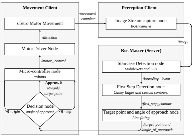
Figure 1.Model Structure
Neural networks have large computation costs. Due to this, computing on low powered 104
hardware in real-time is almost impossible. Hence, we propose a client-server model for real-time 105
applications. The proposed system is built on the ROS platform [28]. ROS provides the infrastructure 106
ROS system. The ROS-based block diagram of the proposed system using a client- server model 108
is shown in Figure1. The ROS topics transmitted in ROS network through WiFi or data networks 109
enable the communication between ROS nodes. Specifically, first, the perception client uses an image 110
sensor to extract an image from the image stream and sends it over to the server. The server uses two 111
steps to detect and localize staircases. The first step involves detection of staircases. This includes 112
extracting features from an RGB image using the MobileNet architectures. We then classify and 113
predict a bounding box using the SSD architecture. These rely on the CNN architecture, which is 114
explained below. The second step has two components. First, we detect the first step of the staircase. 115
The first step information is then used to detect the target pointpx,y, a point close to the center of the 116
first step. The angle of approachθis also computed in this step. We then send this information to the 117
portion of client responsible for movement. Based on our angle of approach, we decide a movement 118
strategy which is executed by the onboard Micro-controller with the help of a motor. While this 119
happens, the perception client updates the server on the new data. This is repeated until the target 120
point is reached. 121
3.1. Convolutional Neural Networks (CNN) 122
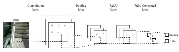
Figure 2.CNN Structure
The CNNs are frequently used in image classification due to their high accuracy. Their structure 123
is the basis for many object detection and image classification networks, including MobileNets and 124
SSD, which we use in our approach. The CNNs consist of four types of layers - Convolution layer, 125
Pooling layer, ReLU layer and a Fully Connected layer. The combination of Convolution layer(s) 126
and Pooling layer(s) extract features from the image. This is fed to the Fully Connected layer(s) that 127
classify the image. Figure2shows the structure of a simple CNN. 128
3.1.1. Convolution layer 129
This layer involves applying a filter over the input layer. Typically, multiple filters are applied on 130
the input layer. Filters are applied using a sliding window, which slides over the image and applies 131
the filter on the region covered by the window. The input layer is zero padded so that the window 132
can cover the entire input. The filter used is called the weight function. Equation1is used to compute 133
the activation function f(x). 134
f(x) =w×x+b (1)
wherewrepresents the filter (weights),brepresents the bias andxrepresents the input. 135
3.1.2. ReLU layer 136
This layer applies a ReLU function to the input layer. This layer is typically used after the 137
Convolution layer. This layer is used to remove the negative values which may have been formed 138
from the filter. Equation2computes the ReLU activation functionf(x). 139
wherexrepresents the input layer. 140
3.1.3. Pooling layer 141
This layer partitions the input layer into non-overlapping regions on which a pooling function is 142
applied. Each region outputs a single value. This reduces the dimension of the input while retaining 143
the important features. 144
3.1.4. Fully connected layer 145
This layer is a typical artificial neural network (ANN) layer. It is fully connected to the input 146
layer. Multiple fully connected layers are used together to classify the image. These are used with the 147
final pooling layer as input. The final pooling layer represents the extracted features. 148
3.2. Feature Extraction using MobileNets 149
Specialized CNN based architectures like MobileNets [25,26], AlexNet [29], Inception [30], 150
ResNet [31]etc. are highly accurate at classifying images. The recently proposed Inception-ResNet 151
[32] has the highest accuracy. However, we use the MobileNet architecture due to its low computation 152
cost, which allows for real-time image classification on mobile hardware [33]. Specifically, we use 153
MobileNetv2 [26], which is an improvement over the standard MobileNet [25]. The basic blocks of 154
both architectures are shown in Figure3 and Figure4. The extracted features of MobileNet is used 155
by SSD architecture to classify and localize staircases. The structure of SSD is discussed in the next 156
section. 157
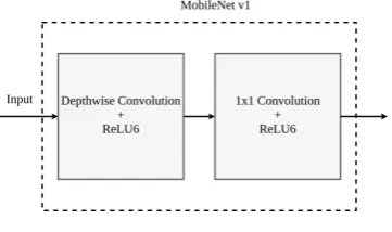
3.2.1. MobileNet architecture 158
The core idea behind MobileNet is depth-wise separable convolutions. These replace the 159
typical convolution layers as computing convolutions are highly expensive. Depth-wise separate 160
convolutions first apply a depth-wise convolution on the input. This filters the input data. This is 161
followed by 1×1 convolutions which combine these filters into features. These depth-wise separable 162
layers approximately mimic the function of typical convolution layers but with much faster speed. 163
Another optimization done was to use ReLU6 instead of ReLU, which applies an upper limit of 6 on 164
the activation function. Equation3is used to compute the activation function f(x). 165
f(x) =min(6,max(0,x)) (3)
wherexis the input. Structure of MobileNet v1 is shown in Figure3.
Figure 3.MobileNet v1
166
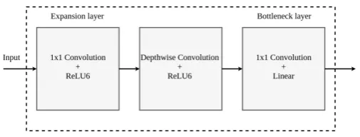
3.2.2. MobileNetv2 architecture 167
MobileNet v2 also uses special convolution structures to replace typical convolution layers. First, 168
there is a expansion layer, which expands the dimension of the input layer tensor. Then the data 169
projection layer, which adds a linear bottleneck to the tensor. This reduces the dimension of the 171
tensor. Structure of MobileNet v2 is shown in Figure4.
Figure 4.MobileNet v2
172
3.3. Localization using Single Shot MultiBox Detector (SSD) 173
Though CNN based architectures with fully connected layers can be used to classify images 174
and detect staircases, autonomous traversal requires the knowledge of location of staircase as well. 175
For this, we need a bounding box over the staircase to calculate its position, which is needed 176
for calculating the target point and the angle of approach. For this purpose, object localization 177
techniques such as Single Shot Multi-Box Detector (SSD) [27], faster R-CNN [34], YOLO [35] etc. 178
can be used. These use the features extracted from CNN based architectures to classify and localize 179
objects. Generally, faster R-CNN is the preferred method for object localization due to best accuracy. 180
However, SSDs have been shown to perform better in most scenarios forlarge objects, which is the case 181
for staircases [33]. SSD is also extremely fast since it requires only one forward pass for computation 182
of all bounding boxes. Due to these reasons, SSD is highly appropriate for the current scenario. 183
3.3.1. SSD architecture 184
SSD passes the input through multiple convolution layers. These layers progressively decrease 185
in size. Each of these layers generate a fixed set of predictions. This enables predictions of various 186
sizes. In addition to this, SSD uses a set of default bounding boxes of different dimensions. These 187
are applied to the predictions from different layers, which allows for predictions of boxes of different 188
sizes and scales. Although the bounding boxes may not be pixel perfect, the loss in accuracy is found 189
to be very minimal. However, due to this, the performance is drastically increased. 190
3.3.2. Loss in SSD training 191
Since SSD involves predicting a bounding box along with the class for an object, typical loss 192
computation cannot be followed. Loss in SSD training is a weighted sum of loss due to two aspects -193
confidence and localization. Equation4is used for computing total lossL. 194
L= 1
N(Lcon f+αLloc) (4)
whereNis the number of matching boxes,αis the weight term which balances the confidence loss 195
Lcon f and localization lossLloc. Confidence loss is the loss that occurs due to classification. This is 196
computed as Softmax of confidence over multiple classes. Localization loss is the loss in predicting 197
the bounding box of the object. This is computed as a smooth L1 loss between predicted box and 198
marked box. 199
3.3.3. Loss optimization 200
We use the Root Mean Square propagation (RMS prop) [36] algorithm to optimize the total loss 201
vt=βvt−1+ (1−β)g2t (5)
∆wrms = √−η
vt+e×gt (6)
wrmst+1=wrmst +∆wrms (7)
wheregt is the gradient along weightwrms. wrmst is the weight at any time t. vtis the exponential 203
average of gradients. η is the inital learning rate. βis a hyperparameter to be tuned. eis constant 204
with value close to zero to avoid dividing by zero errors. 205
3.4. First step detection 206
Through SSD and MobileNets, we are able to detect the staircase and predict a bounding box 207
over it. Now, we require knowledge of the first step to determine the target point and angle of 208
approach. We do this by analyzing the staircase inside the bounding box. These values enable 209
our sTetro robot to move towards the detected staircase autonomously. For detection of steps, the 210
prominent method is Hough transform [37], which detects straight lines. However, steps of staircases 211
may be curved as well. Traditional contour detection is difficulty to handle this situation. Also, we do 212
not need to detect all the contours in the image, as we require only the first step in our calculations. 213
The proposed method for first step of staircase detection can be divided into two parts. First, we 214
detect edges using Canny edge detection, which is followed by contour detection. 215
3.4.1. Edge Detection 216
To be able to detect the first step in the image, we first need to detect edges present in the image. 217
For this, we use the Canny Edge detection algorithm [38].to enhance the accuracy of detected edges, 218
the Canny Edge algorithm is divided into 4 steps - Gaussian filters step to remove the noise, gradient 219
calculation to find the edge pixel candidates, non-max suppression step to remove the edges with the 220
weak gradient responses, hysteresis thresholding step to thin the detected edge lines. This returns a 221
edge representation of the imagei.eonly the pixels that constitute edges are positive. Other pixels are 222
0. 223
3.4.2. Contour detection algorithm 224
This paper proposes a contour detection algorithm for determining the first step as shown in 225
Algorithm1. The algorithm detects points within a certain distance and certain bounds while giving 226
preference to the points along the gradient of the most recent detected points. Before computation, we 227
generatecanny, which is the canny edge representation of the image. We use two functions for this 228
algorithm. FunctiongetContour()returns the contour representing the first step of the staircase. This 229
function usescannyto generate a contour representing the first step. It checks the image from bottom 230
to top (represented byi), left to right (represented byj) direction. If an edge point is detected it calls 231
getContourWithIJ(), with a contour consisting of only the point i,j. Finally, it returns the contour
232
only if its horizontal length is greater than a certain threshold,thresf ilter. We set this to 60% of the 233
width of the staircase during experiments. This is done usinggetBounds(), which gets the difference 234
between horizontal bounds of the contour. 235
FunctiongetContourWithIJ()finds the remaining contour from the reference pointi,jincanny. 236
This is merged with the contour detected prior to this point, which is represented by contour. It 237
consists of 4 steps to identify the next point in the contour. First, the equation of the line that fits 238
the previous 5 points in the contour is generated. The function fitLine() does this by line-fitting 239
linear regression approach [39]. We also set a bound on the slope of the line. linerepresents this line 240
Algorithm 1Contour detection algorithm psuedocode
1: functionGETCONTOUR(canny,thresf ilter) 2: i=canny.length−1;j=0
3: contour= [] 4: whilei>=0do
5: whilej<canny.widthdo
6: contour=GETCONTOURWITHIJ(canny,i,j,contour.append([i,j])) 7: ifgetBounds(contour)>thresf ilterthen returncontour
8: end if
9: j=j+1
10: end while
11: i=i−1 12: end while 13: end function
14: functionGETCONTOURWITHIJ(canny, i, j, contour) 15: arr=empty;t=0
16: line= f itLine(contour) 17: whilet<threswidthdo 18: ycoord=line.slope×(t) +i 19: arr.push(ycoord,j+t, 0) 20: foriteminarrdo
21: bottom=item[0] +item[2]
22: bottomLimit=item[1] +thres×item[1]
23: if canny[bottom][item[1]] > 0 and bottom <= bottomLimit then return GETCONTOURWITHIJ(canny,bottom,item[1],contour.append([bottom,item[1]))
24: end if
25: top=item[0]−item[2]
26: topLimit=item[1]−thres×item[1]
27: if canny[top][item[1]] > 0 and top >= topLimit then return GETCONTOURWITHIJ(canny,top,item[1],contour.append([top,item[1]))
28: end if
29: iftop<topLimitandbottom>bottomLimitthen 30: arr.remove(item)
31: end if
32: item[2] =item[2] +1
33: end for
34: t=t+1 35: end while
36: whilearr.length>0do 37: foriteminarrdo
38: bottom=item[0] +item[2]
39: bottomLimit=item[1] +thres×item[1]
40: if canny[bottom][item[1]] > 0 and bottom <= bottomLimit then return GETCONTOURWITHIJ(canny,bottom,item[1],contour.append([bottom,item[1]))
41: end if
42: top=item[0]−item[2]
43: topLimit=item[1]−thres×item[1]
44: if canny[top][item[1]] > 0 and top >= topLimit then return GETCONTOURWITHIJ(canny,top,item[1],contour.append([top,item[1]))
45: end if
46: iftop<topLimitandbottom>bottomLimitthen 47: arr.remove(item)
48: end if
49: item[2] =item[2] +1
50: end for
51: end whilereturncontour 52: end function
coordinates, represented by variablet. This variable is bound by a threshold threswidth. Using this, 242
we computeycoord, which is the next possible location of the edge. We push this onto an arrayarr. 243
Then, for each element inarr, we search both above and below the elements. If any of them is part of 244
(a) (b)
(c)
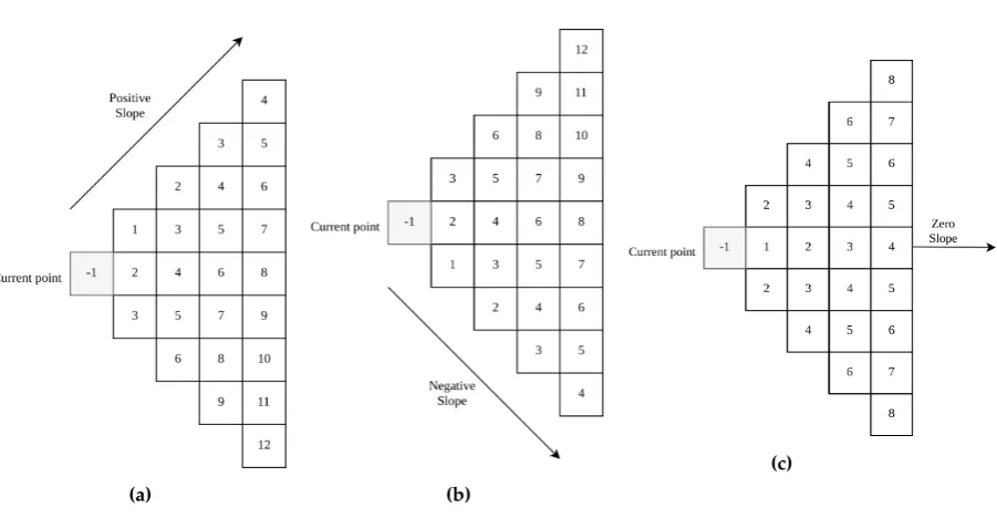
Figure 5. Order of evaluation using the contour algorithm. Positive slope (+45◦) in (a) . Negative slope (−45◦) in (b). Zero slope (0◦) in (c). The angle of 45 is chosen for easy visualization.
this element exists the bound, computed using an angle thresholdthres, the element is removed from 246
the array. 247
The working of algorithm for three different scenarios based on slope ofline, has been shown in 248
Figure5. In this figure, each box represents one pixel in the image. The value in each box represents 249
the iteration in which they would be visited. The box with value−1 represents the current pixel on 250
whichgetContourWithIJ()is called. The line represents the slope for the given scenario, with the 251
value of slope given below each figure. The algorithm clearly gives preference to points along the 252
slope while also examining points in the area bounded bythres. The numbers in boxes represent 253
which iteration of algorithm would evaluate those pixels. For two pixels having same iteration 254
number, the one which is closest to the slope will be evaluated first. 255
3.5. Determining the target point 256
Since we have the contour representing the first step, determining the target point px,y 257
(approximate central position of first step of staircase) is rather simple. We can findnpoints which 258
are closest to the horizontal center. The distance here is linear distance between theX-coordinates, 259
since there would not be multiple points with sameX-coordinate. We can then fit a line through 260
these points and predict the Y-coordinate of the horizontal center. The horizontal point x along 261
X-coordinate and vertical pointyalongY-coordinate gives the central target point px,y. The slope 262
of this line is the angle of approach (θ). This is necessary so that the robot can rotate itself to align 263
with the staircase. In general, negative angles mean the robot is located to the right of the staircase 264
and should rotate clockwise while moving left, so that the robot will become aligned to the staircase. 265
Similarly, positive angles mean the robot is located to the left of the staircase and should rotate 266
counter-clockwise while moving right. Angles close to zero means the robot is already aligned to 267
the staircase. We use a small threshold around zero to accommodate for slight variations, which may 268
occur during detection. 269
4. Experimental Setup 270
In this section, we discuss about the data-set specification and specification of the models used. 271
(a) (b) (c)
Figure 6. sTetro robot capturing images from different angles. (a) left of staircase, (b) in front of staircase, (c) right of staircase.
Figure 7.Some of the images present in the dataset.
of this is discussed below. The weights of the network were initialized to the weights of a network 273
trained on the COCO data-set [40], which is a large data-set containing 80 most common classes for 274
labelling. This was done so that there would be a faster convergence while training. This also helps 275
in achieving a better overall accuracy. We used a batch size of 20 while training. We used a RMS prop 276
optimizer for loss optimization with initial learning rate 0.004 and a decay factor of 0.9. 277
4.1. Obtaining Data-set 278
The sTetro robot [7] is used to capture images of the working environment. A RGB camera is 279
fitted on top of sTetro robot, which is used to take the images, as shown in Figure6. Initially the 280
images are taken from different staircases at different angles ranging from approximately 0 to 180 in 281
front of stairs. Images from different distances and different positions were also taken. All images 282
have a resolution 640×480 pixels. The data-set consists of 1025 images. The data-set contains images 283
of 11 different staircases, which include both straight and curved staircases. Staircases with curved 284
steps were also taken. The data-set also has staircases with different materials. A 90 : 10 split was 285
taken for training and testing respectively during the training phase. Figure7contains some of the 286
The final results are obtained from a set of 102 images not present in the data-set. Approximately 288
half of these images contain staircases in them. The other half includes images of corridors, open areas 289
and other common environments for cleaning robots where objects with features similar to staircases 290
may be present. 291
5. Results Discussion 292
In this section, we discuss about the results obtained on the staircase data-set used. We divide 293
this section into two categories: Staircase detection and First step detection. 294
5.1. Staircases Detection 295
(a) (b) (c) (d)
(e) (f) (g) (h)
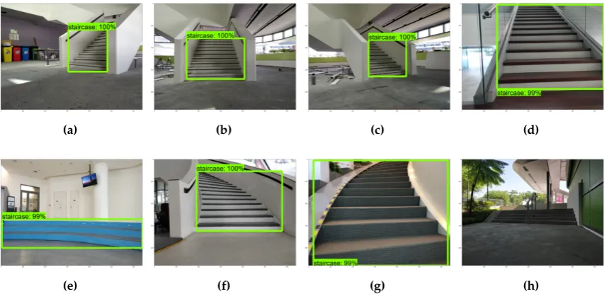
Figure 8.Staircase detection. Staircase detected in (a), (b), (c), (d), (e), (f) and (g). Not detected in (h).
This section discusses results pertaining to detection of bounding boxes over staircases. Some 296
images of staircases were taken along with images having similar features to staircases. This includes 297
structures with parallel lines, ladders, floors with texturesetc. The model detected almost all staircases 298
correctly. This includes different types of staircases and images taken from different angles and 299
distances. This is shown in Figure8. The box represents detected staircase. The confidence of its 300
prediction is shown as a percentage above/ below the box. We filter out boxes with confidence less 301
than 80% for staircase localization. Figures8a,8band8cshow the model is able to detect staircases 302
viewed from different angles. Figure8dis another staircase with different material. Figure 8eis 303
a staircase with curved steps, which the model is able to recognize. Figures8f and8gare curved 304
staircases with different orientations. The model is able to detect these as well. In Figure 8h, the 305
staircase is not detected. This can be attributed to bad lighting conditions and larger distance between 306
the robot and the staircase. The modeldid notdetect ladders as staircases, which is a common issue 307
with traditional methods. Also, the model is able to detect curved staircases, which proves to be a 308
challenge for traditional linear line detection based-approaches. 309
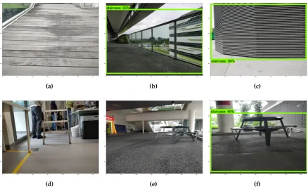
However, the model did fail on certain cases where the images were very similar to staircases. 310
Some examples of these scenarios are given below in Figure 9. The model is able to differentiate 311
between staircases and tiled floors, which have parallel lines. One such example is Figure9a. This is a 312
very common scenario where traditional classifiers struggle, since the floor has parallel lines, which is 313
a common feature used to detect staircases. Figure9bis detected as a staircase. This can be attributed 314
to the fact that the railings look like a staircase rotated by 90. However, it is easy to differentiate 315
(a) (b) (c)
(d) (e) (f)
Figure 9.Negative samples for staircase detection. Staircases are not detected in (a), (d) and (e). False detection in (b), (c) and (f).
features similar to a staircase, which causes the model to detect it as a staircase. The model also 317
does not detect ladders as staircases. This is shown in Figure9d. In Figure9e, the combination of 318
table and chair is also not recognized as staircases, although they have similar features. However, 319
when combined with lines on the floor, the model detects them as a staircase, as shown in Figure 320
9f. However, if we put a constraint on the height of steps i.ea constraint on distance between two 321
contour lines, this false detection may be avoided. The overall results are given in Table1. 322
Table 1.Results of staircase detection.
Labelled Staircase Not Detected Total Precision (%)
Staircase 42 2 44 95.45
Not Staircase 14 44 58 75.86
Any Image 56 46 102
-5.2. First step detection results 323
This section discusses results pertaining to detection of first step of staircases. We use 60% width 324
of staircase as thethresf ilterto filter out small contours. Also, we filter out all vertical edges by using a 325
thresparameter of≈60◦. This value is obtained from grid searching through possible values forthres 326
and selecting the one with best accuracy. The algorithm is able to detect both the target point px,y 327
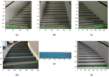
and the angle of approachθwith good accuracy. The results are showcased in Figure11. Here, the 328
first step of the staircase detected using contour detection is denoted by the line. The cross represents 329
the computed target pointpx,y. The detected angle of approachθis also shown below each Figure. 330
The algorithm is able to detect these with good accuracy, as shown in Figures11a,11b,11c,11e,11f. 331
(a)
(b)
(c)
Figure 10. Canny edge detection. (a) Noisy edge detection. (b) Curved step edge detection. (c) Straight staircase edge detection.
(a) (b) (c)
(d)
(e)
(f)
Figure 11.First step detection. (a) Detected angle: -6.724, move left. (b) Detected angle: 0.678, move towards target point. (c) Detected angle: 5.386, move right. (d) Detected angle: 18.336816, move right. (e) Detected angle: -4.586, move left. (f) Detected angle: 0, move towards target point.
noise generated during Canny Edge detection. The edges detected for this image is shown in Figure 333
10a. Optimal edge detection results are shown in Figures10band10c. 334
5.3. Real-time Performance 335
This section details the real-time tests performed using our proposed model. We used an image 336
(a) (b) (c) (d) (e)
(f) (g) (h) (i) (j)
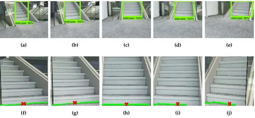
Figure 12.Real time staircase detection. (a), (b), (c), (d) and (e) are staircase detection results. (f) is the fist step detected in (a) (instruction: move right). (g) is the fist step detected in (b) (instruction: move right). (h) is the fist step detected in (c) (instruction: move straight). (i) is the fist step detected in (d) (instruction: move left). (j) is the fist step detected in (e) (instruction: move left).
Table 2.Performance of proposed approach.Times do not include network delays.
Scenario Maximum Time(ms) Average Time(ms)
Staircase Detection 2652 71
First Step Detection 930 83
Total 2684 155
able to detect staircases by sending frames after every interval to a server where the server processed 338
and returned a direction logic (i.eangle of approach) to the robot. Also, the details of the target point 339
was sent so that the robot can move towards this location. In this test, the robot is moving from the 340
left to the right of staircase. Detection of staircase during this test is shown in Figures12a,12b,12c, 341
12dand12e. The first step detection for these Figures are shown in Figures12f,12g,12h,12iand12j 342
respectively. The directions predicted are accurate during our testing scenarios, with minor errors 343
occurring on textured staircases. The target point is predicted accurately. However, for real-time 344
applications, the running time of the algorithm is also crucial. This is given in Table2. The overall 345
approach takes about 150mson an average, which is feasible for real-time applications. The high 346
computation times usually occur during the first run, which can be attributed to the loading of model 347
into memory. 348
6. Conclusion 349
In this paper, we described an approach to staircase recognition and localization. We first used 350
a deep learning model to recognize a staircase in the environment. This was done using an object 351
detection network consisting of MobileNet and SSD architectures. We then used canny edge detector 352
followed by our own contour detection algorithm for first step detection of staircase. Through this, 353
we identified the target point, a point close to the center of the first step and the angle of approach, 354
which is used to determine the direction to staircase. This scheme allows to align the robot to the 355
staircase, so that it can start traversing the staircase. We trained and tested our proposed model 356
using our own data-set consisting of images of 11 different staircases captured with sTetro robot from 357
The model is able to detect staircase and determine the target point and the angle of approach to the 359
first step of the staircase with good accuracy. We also tested this model for real-time scenarios and 360
found that it can be used in slow moving platforms like sTetro. In future, this work can be extended 361
to recognize the type of staircases also, like straight, curved, spiraletc. This would allow the robot to 362
switch between operation modes according to the type of staircase encountered. 363
7. Acknowledgement 364
This research was supported by Grant No. RGAST1702 from National Robotics Program 365
Office, Singapore (NRPO) to the Engineering Product Development (EPD) at Singapore University 366
of Technology and Design (SUTD). 367
References 368
1. Prassler, E.; Ritter, A.; Schaeffer, C.; Fiorini, P. A short history of cleaning robots.Autonomous Robots2000, 369
9, 211–226. 370
2. Jones, J.L.; Mack, N.E.; Nugent, D.M.; Sandin, P.E. Autonomous floor-cleaning robot, 2017. US Patent 371
App. 15/451,817. 372
3. Prabakaran, V.; Elara, M.R.; Pathmakumar, T.; Nansai, S. Floor cleaning robot with reconfigurable 373
mechanism.Automation in Construction2018,91, 155–165. 374
4. Choset, H. Coverage for robotics–A survey of recent results.Annals of mathematics and artificial intelligence 375
2001,31, 113–126. 376
5. Biswas, J.; Veloso, M. Wifi localization and navigation for autonomous indoor mobile robots. Robotics 377
and Automation (ICRA), 2010 IEEE International Conference on. IEEE, 2010, pp. 4379–4384. 378
6. Huang, A.S.; Bachrach, A.; Henry, P.; Krainin, M.; Maturana, D.; Fox, D.; Roy, N. Visual odometry and 379
mapping for autonomous flight using an RGB-D camera. InRobotics Research; Springer, 2017; pp. 235–252. 380
7. Ilyas, M.; Yuyao, S.; Elara, M.R.; Devarassu, M.; Kalimuthu, M. Design of sTetro: A Modular, 381
Reconfigurable and Autonomous Staircase Cleaning Robot. Journal Of Sensors (in press). 382
8. Munoz, R.; Rong, X.; Tian, Y. Depth-aware indoor staircase detection and recognition for the visually 383
impaired. Multimedia & Expo Workshops (ICMEW), 2016 IEEE International Conference on. IEEE, 2016, 384
pp. 1–6. 385
9. Duda, R.O.; Hart, P.E. Use of the Hough transformation to detect lines and curves in pictures. 386
Communications of the ACM1972,15, 11–15. 387
10. Sinha, A.; Papadakis, P.; Elara, M.R. A staircase detection method for 3D point clouds. Control 388
Automation Robotics & Vision (ICARCV), 2014 13th International Conference on. IEEE, 2014, pp. 389
652–656. 390
11. Oßwald, S.; Hornung, A.; Bennewitz, M. Improved proposals for highly accurate localization using 391
range and vision data. Intelligent Robots and Systems (IROS), 2012 IEEE/RSJ International Conference 392
on. IEEE, 2012, pp. 1809–1814. 393
12. Johnson, A.M.; Hale, M.T.; Haynes, G.; Koditschek, D.E. Autonomous legged hill and stairwell ascent. 394
Safety, Security, and Rescue Robotics (SSRR), 2011 IEEE International Symposium on. IEEE, 2011, pp. 395
134–142. 396
13. Mihankhah, E.; Kalantari, A.; Aboosaeedan, E.; Taghirad, H.D.; Ali, S.; Moosavian, A. Autonomous 397
staircase detection and stair climbing for a tracked mobile robot using fuzzy controller. Robotics and 398
Biomimetics, 2008. ROBIO 2008. IEEE International Conference on. IEEE, 2009, pp. 1980–1985. 399
14. Hernández, D.C.; Jo, K.H. Stairway tracking based on automatic target selection using directional filters. 400
Frontiers of Computer Vision (FCV), 2011 17th Korea-Japan Joint Workshop on. IEEE, 2011, pp. 1–6. 401
15. Cong, Y.; Li, X.; Liu, J.; Tang, Y. A stairway detection algorithm based on vision for ugv stair climbing. 402
Networking, Sensing and Control, 2008. ICNSC 2008. IEEE International Conference on. IEEE, 2008, pp. 403
1806–1811. 404
16. Se, S.; Brady, M. Vision-based detection of staircases. Fourth Asian Conference on Computer Vision 405
17. Hesch, J.A.; Mariottini, G.L.; Roumeliotis, S.I. Descending-stair detection, approach, and traversal with 407
an autonomous tracked vehicle. Intelligent Robots and Systems (IROS), 2010 IEEE/RSJ International 408
Conference on. IEEE, 2010, pp. 5525–5531. 409
18. Lu, X.; Manduchi, R. Detection and localization of curbs and stairways using stereo vision. Robotics and 410
Automation, 2005. ICRA 2005. Proceedings of the 2005 IEEE International Conference on. IEEE, 2005, pp. 411
4648–4654. 412
19. LeCun, Y.; Bengio, Y.; Hinton, G. Deep learning. nature2015,521, 436. 413
20. Schmidhuber, J. Deep learning in neural networks: An overview.Neural networks2015,61, 85–117. 414
21. Ji, S.; Xu, W.; Yang, M.; Yu, K. 3D convolutional neural networks for human action recognition. IEEE 415
transactions on pattern analysis and machine intelligence2013,35, 221–231. 416
22. Weninger, F.; Bergmann, J.; Schuller, B. Introducing currennt: The munich open-source cuda recurrent 417
neural network toolkit. The Journal of Machine Learning Research2015,16, 547–551. 418
23. Chetlur, S.; Woolley, C.; Vandermersch, P.; Cohen, J.; Tran, J.; Catanzaro, B.; Shelhamer, E. cudnn: Efficient 419
primitives for deep learning. arXiv preprint arXiv:1410.07592014. 420
24. Girshick, R.; Donahue, J.; Darrell, T.; Malik, J. Region-based convolutional networks for accurate object 421
detection and segmentation. IEEE transactions on pattern analysis and machine intelligence2016,38, 142–158. 422
25. Howard, A.G.; Zhu, M.; Chen, B.; Kalenichenko, D.; Wang, W.; Weyand, T.; Andreetto, M.; Adam, 423
H. Mobilenets: Efficient convolutional neural networks for mobile vision applications. arXiv preprint 424
arXiv:1704.048612017. 425
26. Sandler, M.; Howard, A.; Zhu, M.; Zhmoginov, A.; Chen, L.C. Inverted Residuals and Linear Bottlenecks: 426
Mobile Networks for Classification, Detection and Segmentation. arXiv preprint arXiv:1801.043812018. 427
27. Liu, W.; Anguelov, D.; Erhan, D.; Szegedy, C.; Reed, S.; Fu, C.Y.; Berg, A.C. Ssd: Single shot multibox 428
detector. European conference on computer vision. Springer, 2016, pp. 21–37. 429
28. Quigley, M.; Conley, K.; Gerkey, B.; Faust, J.; Foote, T.; Leibs, J.; Wheeler, R.; Ng, A.Y. ROS: an open-source 430
Robot Operating System. ICRA workshop on open source software. Kobe, Japan, 2009, Vol. 3, p. 5. 431
29. Krizhevsky, A.; Sutskever, I.; Hinton, G.E. Imagenet classification with deep convolutional neural 432
networks. Advances in neural information processing systems, 2012, pp. 1097–1105. 433
30. Szegedy, C.; Vanhoucke, V.; Ioffe, S.; Shlens, J.; Wojna, Z. Rethinking the inception architecture for 434
computer vision. Proceedings of the IEEE Conference on Computer Vision and Pattern Recognition, 435
2016, pp. 2818–2826. 436
31. He, K.; Zhang, X.; Ren, S.; Sun, J. Deep residual learning for image recognition. Proceedings of the IEEE 437
conference on computer vision and pattern recognition, 2016, pp. 770–778. 438
32. Szegedy, C.; Ioffe, S.; Vanhoucke, V.; Alemi, A.A. Inception-v4, inception-resnet and the impact of residual 439
connections on learning. AAAI, 2017, Vol. 4, p. 12. 440
33. Huang, J.; Rathod, V.; Sun, C.; Zhu, M.; Korattikara, A.; Fathi, A.; Fischer, I.; Wojna, Z.; Song, Y.; 441
Guadarrama, S.; others. Speed/accuracy trade-offs for modern convolutional object detectors. IEEE 442
CVPR, 2017. 443
34. Ren, S.; He, K.; Girshick, R.; Sun, J. Faster r-cnn: Towards real-time object detection with region proposal 444
networks. Advances in neural information processing systems, 2015, pp. 91–99. 445
35. Redmon, J.; Divvala, S.; Girshick, R.; Farhadi, A. You only look once: Unified, real-time object detection. 446
Proceedings of the IEEE conference on computer vision and pattern recognition, 2016, pp. 779–788. 447
36. Tieleman, T.; Hinton, G. Lecture 6.5-RMSProp, COURSERA: Neural networks for machine learning. 448
University of Toronto, Technical Report2012. 449
37. Ballard, D.H. Generalizing the Hough transform to detect arbitrary shapes. Pattern recognition1981, 450
13, 111–122. 451
38. Canny, J. A computational approach to edge detection. IEEE Transactions on pattern analysis and machine 452
intelligence1986, pp. 679–698. 453
39. Edwards, A.L.An introduction to linear regression and correlation; WH Freeman San Francisco, 1976. 454