Sensorless Vector Control Ofof Permanent Magnet
Synchronous Motor Based On Current Sampling
LI Peng,WEI Hai-feng,ZHANG Yi
(School of Electrical and Information, Jiangsu University of Science and Technology, Zhenjiang 212003)
Abstract: Sensorless vector control strategy of permanent magnet synchronous motor (PMSM) based on IRMCF341341 is introduced,and rotor position detection based on a low cost of current sampling strategy is presented. No position system simulation model and system software and hardware design are built. The test results show that the control strategy is feasible and practical in the application of permanent magnet synchronous motor.
Keywords: PMSM; no position sensor; vector control ;IRMCF341; current sampling;
0 Introduction
Permanent magnet synchronous motor don’t need exiting current, operating efficiency and
power destiny are both very high, however its high-performance control needs accurate rotor position and rate signal to achieve flux-oriented control. In motion control system of traditional
permanent magnet synchronous motor, usually we use photoelectric coding disk or resolver to sampling rotor position and rotor rate. However, these sensor raises the cost of system control, and reduced the reliability of the system. Therefore, it becomes more and more popular to call off
these devices to improve the reliability of the system.
1 Vector control of permanent magnet synchronous motor
This article uses vector control which based on id=0, for permanent magnet synchronous motor we use the control mode of id=0, we can linearly control torque of the motor by control the
size of quadrature axis currents.
ref n PI qref i PI d u SVPWM uα Inventer PI 0 def
i = uβ
, α β , α β q
i
d i , α β , ,a b c
PMSM iα , d q , d q iβ a i b i c i − − − + + + q
u UDC
n Speed feedback
q
Fig.1 Vector control block diagram of permanent magnet synchronous motor based on
Firstly, the rotor position and speed acquisition unit system speed, the speed difference between the output and the speed of set by PI controller is used as the reference value of the
torque current component, excitation current component of the reference value of is set to 0, the motor stator windings of three-phase current, by Clark transform and after the Park transform get
0
d
actual torque component of current and excitation current component , two components were set by PI and the difference between the regulator output voltage under the rotating coordinate
component and , two components by Park inverse transform in two-phase static coordinates and voltage component, The two component is modulated by the SVPWM module generates six PWM
signals to the three-phase inverter, the inverter control motor speed and torque.
2
The simulation study of sensorless
2.1Strategy of sampling of low-cost current
At present, most of permanent magnet synchronous motor driver generally use at least two
hall current sensor to sampling the phase current of the motor. Obviously this simulation raised the cost and complexity level. Therefore we need a kind of simulation of current sampling which is low-cost and for the best it has only one current sampling unit. One way which is grown is to
using current and PWM signal to rebuild the project of phase current of the motor. This system is built with this low-cost current sampling simulation.
P N SVPWM A/D Current Calculation 1
T T3 T5
2
T T4 T6
S R a i b i c i + − a b c
Fig.2 System structure based on bus current sampling
s
R
is sampling resistor in negative DC side voltage of the A/D converter, direct acquisition sampling resistor value. Combined with the PWM switch vector information of the current draw phase current value, the following will analyze the relationship between the bus current and PWM vector.P +
N -S R a b c DC V 0 DC i = P +
N -S R a b c DC V DC a
i =i
a i a i c i
(a) (b) P +
N -S R a b c DC V DC a
i = −i
c i a i a i P +
N -S R a b c DC V DC b
i =i
b
i
b
i ic
(c) (d)
As shown in Figure 4 there are two non-zero switching vectors in each PWM period. There is two different phase current in each PWM period. DC bus can get another phase current value
through a simple addition and subtraction. Thus the motor phase current sampling method is feasible in order to obtain better effect. The sampling, is proposed to avoid the influence of
sampling switch brings the switch in the middle of vector function time, as long as the and time sampling can be obtained respectively and calculated, can also choose in the current set up stable immediately after sampling. There are also researchers proposed Due to the phase current,
frequency of the motor is much lower than the switching frequency of PWM, so it can be considered that in a PWM cycle phase current is constant, so it can be in the first half of the PWM
cycle in the moment for the first time the current sampling, and wait until the second half cycle time second electric current sampling. The advantage of this is that between widening A/D converter two conversion interval, greatly reduce the performance requirements of the A/D
converter.
Tab.1 Table of the relationship between switching state and sampling current
Switch State
Sampling Current
000 100 110 010 011 001 101 111
0
i
a−
i
ci
b−
i
ai
c −ib 0Sector
V0 V1 V2 V3 V4 V5 V6 V7a
i
a
i
c
i
−
−
i
c1
τ τ2
* 1 τ *
2 τ
DC
i
110 111 111 110 100 000 000 100
a
b
c
t
Fig.4 The relationship between the switching state of a PWM cycle and bus current in an ideal condition
2.2 Rotor position decision modeling and simulation
Low cost current sampling method presented above, the three-phase current through the
sampling resistor negative bus can obtain the motor, this section through the simulation modeling to determine the rotor position of permanent magnet synchronous motor.
Permanent magnet motor normal operation current in the three-phase winding is the same
frequency with the phase difference of 120 degree sine wave, strategy we have to obtain the current in the three-phase winding from the current day sampling to obtain the rotor position
information as follows from the modeling and Simulation of three-phase current.
In a circuit as an example, the V3 phase current windings, the design is used in the input and output of the comparator four, when the V3 is in the upper half sine (
>
0
) comparator output is 0,Fig.5 Rotor position simulation of a phase current
Figure 6 is a comparison of two input output current, input signal frequency the same phase difference of 120 degrees, the output frequency is the same with the phase difference of 120
degree square wave signal.
Fig.6 Two input - output contrast diagram
Figure 7 is a three-phase square wave output signal, a record high level time is 1, the low
level of 0, in a power cycle three-phase winding signal can be expressed by the following figure.
Fig.7 Three phase square wave output
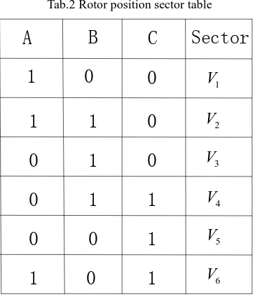
Remember a moment of high level is 1, the low level of 0, according to figure 7 can wait until a period of electric rotor position of the sector Table 2 contact sections, namely through the sampling resistor negative bus can get to the three-phase current information, in accordance with
this section through the three-phase current to obtain the rotor position and sectors, so as to achieve control of the motor.
Tab.2 Rotor position sector table
A
B
C
Sector
1
0
0
1
1
0
0
1
0
1
1
0
0
0
1
1
0
1
1
V
2
V
3
V
4
V
5
V
6
1
V
2
V
3
V
4
V
5
V
6
V
Fig.8 Rotor position sector
2.3 Without position sensor simulation and modeling
According to the permanent magnet synchronous motor rotor position determination method and vector control strategy, we first construct the simulation model of permanent magnet
synchronous motor as id = 0 position sensorless control of the double loop.
Fig.9 Vector control model of double closed loop permanent magnet synchronous motor
Figure 9 is a double closed loop of permanent magnet synchronous motor vector control simulation model, the inner loop adopts vector control strategy, the outer loop is the speed
tracking.
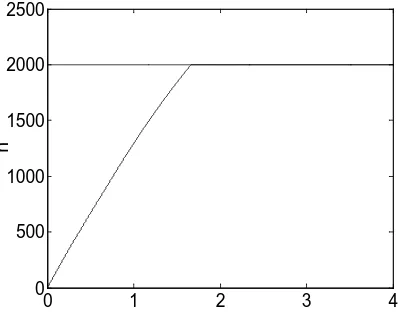
The parameters of motorR=1.11Ω, Ld=16.6e-3H, Lq=16.45e-3H, Ψ ≈f 0.5072wb set
the load torque for a given speed 2000, get the speed response waveform and phase voltage waveforms respectively. Figure 10 can be seen after the starting of the motor speed with speed
setting quickly run to the 2000 system, fast response, small overshoot, good control performance.
0 1 2 3 4
0 500 1000 1500 2000 2500
Fig.11 Phase voltage
3 The hardware and software system design
3.1 Hardware design 3.1.1Power circuit
The design of the driving circuit with intelligent power module IPM, intelligent power module not only the switching device and the drive circuit are integrated together, and has
integrated overcurrent, overheating and short circuit protection and fault detection circuit. The design of the IPM intelligent power module PS21A79 Mitsubishi, the maximum input voltage 600V, maximum output the current 75A, maximum switching frequency is 20KHz, can well meet
the design requirements of control system. 3.1.2 Power supply circuit
The system needs to provide the required power supply circuit to each chip, switching power supply control chip with high performance fixed frequency current mode UC2843BD1. controller of TI company
The main power supply circuit for 150~300V DC input, switch transformer output a 15V/500mA to provide 15V reference voltage for the power supply control chip, the power switch
transformer output a 6V~7V/500mA three terminal regulator SPX1117-3.3 and SPX1117-1.8 in cascade output 3.3V/1A and 1.8V/ 1A respectively provide power supply for the IRMCF341. 3.1.3 negative bus single resistor current sampling circuit
The current sampling precision and real-time largely determines the system's dynamic and static performance, current detection precision is to improve the system control precision, stability
and rapidity of the important link, is to achieve the high performance of the closed-loop control system of key internal integrated.IRMCF341 12 AD 1.8V power supply, the input voltage range is 0~1.2V. The reference voltage for the MCE is 0.6V. The sampling circuit as shown in figure 12:
3.8 3.85 3.9 3.95 4
-600 -300 0 300 600
IFBO
IFB-IFB+
AREF
0.6V 1.8V
S/H1
S/H2
MUX A/D
Rescont ruction
A
B
C
Q1 Q3 Q5
Q2 Q4 Q6
P
N Rs
R1 R2 R3
R4 R5
R6 C1
C2
Fig.12 Single resistance current sampling circuit
s
R is sampling resistance, this design selection Rs =10mΩ,, R1=R4=1K,R2=R5=4K.
The current amplifier gain:
3 1 2
10
1.6393 1 5.1
R A
R R
= = =
+ +
So the 1A current can reflect the input terminal of the signal in AD:
10mΩ×1.6393 16.38= mV The corresponding values for AD quantization:
4096
16.39 56
1200
mV× = (AD 0-1.2V corresponding to 0-4095)
However, due to the resistance error, gain error and other reasons, the current ratio is a bit
error in figure C76 is part of high frequency oscillation signal filter sampling current, the general value of 47pF, the whole gain amplifier circuit can be neglected.
3.2 Software design
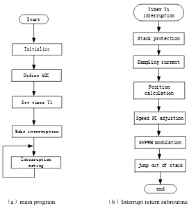
The system software is programmed by C, which is mainly composed of the main program and interrupt service subroutine, the main program complete hardware initialization, definition
and initialization of variables within the inverter set and initialization state detection and program. Interrupt service subroutine includes PWM interrupt service subroutine and interrupt subroutine,
over-voltage, over-current protection, drive protection, complete blockade pulse and alarm function. Then enter the open loop start program, set the timer T1 as the system clock, running into the closed loop. PWM interrupt current voltage detection, rotor position detection, speed
Start
Initialize
Define ADC
Set timer T1
Make interruption
Interruption wating
Timer T1 interruption
Sampling current
Position calculation
Speed PI adjustion
SVPWM modulation
Jump out of stack Stack protection
end
(a)main program (b)Interrupt return subroutine Fig.13 Block diagram
4 Experimental study
According to the requirements of the software and hardware design, this paper constructed IRMCF341 permanent magnet synchronous motor based on position sensorless vector control
system.
Figure 14 is the starting of motor phase current waveform, Figure 15 is no-load speed of 2250rpm (Figure 4500 value corresponding to the 2250rpm), the phase current waveform and
motor speed tracking waveform. The machine starts with four stages, one stage is Park rotor positioning stage, the phase current waveform by forcibly injected DC current is the rotor of the
motor to reach the designated position and stops at the position, the sensorless FOC algorithm to know the exact position before the start of the rotor; the second stage is the open-loop acceleration stage, estimate the rotor angle using the motor model is simple; the third stage is the closed loop
acceleration stage, transport speed To 500rpm (1000 value corresponding to the 500rpm loop) starting stage, motor speed up, speed up the voltage of the motor, the rotor angle of useful
information extracted from the motor voltage and motor into the closed loop mode; the fourth stage is the stage of stable operation, the closed-loop operation of the motor to the setting speed, sustained and stable operation the phase current map in the open. There is a big wave ring stage,
Fig.14 Motor starting phase current
Fig.15 Motor start speed waveform
5 Conclusion
This paper presents sensorless control of permanent magnet synchronous motor based on
IRMCF341 control chip and the sampling strategy and determine the position of the rotor current detection method based on a low cost current was set up. The position system simulation model
and system hardware and software design, test results show that the control strategy can in the permanent magnet owns the feasibility and practicability of using synchronous motor.
Acknowledgment.
This work was financially supported by National Natural Science
Foundation of China (61503161).
References
[1] Guo Q F, Liang B, Zhang Y L. Application of PMSM Drive System in Air-conditioning[J]. Power Electronics, 2011, 2: 015.
[2] Ping X, Jing B. SMC with disturbance observer for high performance PMSM[C] Mechatronical Science, Electric Engineering and Computer (MEC), 2011 International Conference on. IEEE, 2011: 986-989. [3] Yao H L, Wei G L. A comparative study of vector control and direct torque control of permanent magnet
synchronous motor [J].Electric Drive,2010,40(10):9-16.
[4] Shu R F, Qi L, Yan F Z Cortex-M3 Principle and application of embedded processor [M].BeiJing:
Publishing House Of Electronics Industry,2011.
[5] Qin B Hu. Permanent Magnet synchronous motor inverter design based on STM32F103,2013,(12):51-54 [6] Yong M W, ShenC W, Review of sensorless control technology of permanent magnet motor based on