Detection of Ozone Layer Depletion Using Image
Processing and Data Mining Technique
Nomula Divya
#1,Narasimha Prasad Lakkakula
*2,Arjun Nelikanti
#3 #1M. Tech Student,
*2Professor And Director,
#3M.Tech Student
Dept. of CSE, Vardhaman College of Engineering
Hyderabad, India.
Abstract— There are many situations where human activities have significant effects on the environment. Ozone layer damage is one of them. This paper presents methodology for detection of ozone layer depletion using satellite imagery of O3. The chlorofluorocarbon and the Greenhouse gases are
potent ozone depletors. One of the main reasons for the widespread concern about depletion of the ozone layer is the anticipated increase in the amounts of ultraviolet radiation received at the surface of the earth and the effect of this on human health and on the environment. The present analysis applies k-means clustering on the satellite imagery in order to compute normality for O3. By using normality, pH value is
computed and if the value lies in the range of 1 ≤ pH ≤ 5, it is identified as ozone layer depletion. The proposed methodology is addressed for the first time using data mining and image processing. The resulted outcome indicates that the amount of rainfall with the concentration of O3 have a strong influence
on the occurrence of ozone layer depletion.
Keywords- Ozone Layer Depletion, K-means clustering; Normality, pH value, Satellite imagery.
I.
I
NTRODUCTIONThe ozone layer is a layer in Earth's atmosphere which contains relatively high concentrations of ozone (O3). This layer absorbs 93-99% of the sun's high frequency ultraviolet light, which is potentially damaging to life on earth[1] . Over 91% of the ozone in Earth's atmosphere is present here.It is mainly located in the lower portion of the stratosphere from approximately 10 km to 50 km above Earth, though the thickness varies seasonally and geographically[2].
A. Ozone
Ozone(O3) is the major component of smog. Without ozone, life on Earth would not have evolved in the way it has. The first stage of single cell organism development requires an oxygen-free environment. This type of environment existed on earth over 3000 million years ago. As the primitive forms of plant life multiplied and evolved, they began to release minute amounts of oxygen through the photosynthesis reaction (which converts carbon dioxide into oxygen) [3]. The buildup of oxygen in the atmosphere led to the formation of the ozone layer in the upper atmosphere or stratosphere. This layer filters out incoming radiation in the "cell-damaging" ultraviolet (UV) part of the spectrum. Thus with the development of the ozone layer came the formation of more advanced life forms. Ozone is a form of oxygen. The oxygen we breathe is in the form of oxygen molecules (O2) two atoms of oxygen bound together. Normal oxygen which we breathe is colorless and odorless. Ozone, on the other hand, consists of three atoms of oxygen bound together (O3).
B. Ozone Hole
The term "ozone hole" should be applied to regions where stratospheric ozone depletion is so severe that levels fall below 200 Dobson Units (D.U.), the traditional measure of stratospheric ozone. Normal ozone concentration is about 348 to
380 D.U [3]. Such ozone loss now occurs at Australia, where special meteorological conditions and very low air temperatures accelerate and enhance the destruction of ozone loss by man-made ozone depleting chemicals (ODCs).
C. Ozone Layer
The ozone layer is a layer, become known as such because most ozone particles are scattered between 19 and 30 kilometers (12 to 30 miles) up in the Earth's atmosphere, in a region called the stratosphere. The concentration of ozone in the ozone layer is usually under 10 parts ozone per million [5]. Without the ozone layer, a lot of ultraviolet (UV) radiation from the Sun would not be stopped reaching the Earth's surface, causing untold damage to most living species. In the 1970s, scientists discovered that chlorofluorocarbons (CFCs) could destroy ozone in the stratosphere. Ozone is created in the stratosphere when UV radiation from the Sun strikes molecules of oxygen (O2) and causes the two oxygen atoms to split apart. If a freed atom bumps into another O2, it joins up, forming ozone (O3). This process is known as photolysis. Ozone is also naturally broken down in the stratosphere by sunlight and by a chemical reaction with various compounds containing nitrogen, hydrogen and chlorine. These chemicals all occur naturally in the atmosphere in very small amounts. In an unpolluted atmosphere there is a balance between the amount of ozone being produced and the amount of ozone being destroyed. As a result, the total concentration of ozone in the stratosphere remains relatively constant. At different temperatures and pressures (i.e. varying altitudes within the stratosphere), there are different formation and destruction rates. Thus, the amount of ozone within the stratosphere varies according to altitude. Ozone concentrations are highest between 19 and 23 km [6]. Most of the ozone in the stratosphere is formed over the equator where the level of sunshine striking the Earth is greatest. It is transported by winds towards higher latitudes. Consequently, the amount of stratospheric ozone above a location on the Earth varies naturally with latitude, season, time-to time and from day-to-day.
Figure: 1. Layers of Atmosphere
D. Measuring Ozone Depletion
earliest studies on ozone in the atmosphere from the 1920s to the 1970s. A Dobson Unit measures the total amount of ozone in an overhead column of the atmosphere. Dobson Units are measured by how thick the layer of ozone would be if it were compressed into one layer at 0 degrees Celsius and with a pressure of one atmosphere above it. Every 0.01 millimeter thickness of the layer is equal to one Dobson Unit. The average amount of ozone in the stratosphere across the globe is about 300 DU (or a thickness of only 3mm at 0°C and 1 atmospheric pressure).
Many studies have focused on developing effective methods for detection of ozone layer depletion patterns by applying algorithms like TOMS, DOAS, ,SCIAMACY, DIAL and techniques like decision trees, artificial neural networks, numerical weather prediction models and statistical approaches and uses different spectrometers like ozone sonde , gome etc. Unfortunately they do not seem able to provide accurate detection of ozone layer depletion predictions at the temporal and spatial resolutions required for meteorology. Therefore interesting options is offered by the use of remote sensing observations through satellite images whose output may provide useful information about detection of ozone layer depletion patterns and also allow obtaining now casting with improved performances. The methodology is based on four stages: Firstly, satellite images containing ozone(O3) and water vapour(h20) images are
segmented using k-means clustering technique [8-10] to identify the O3 concentration parts and water vapour concentration parts.
Secondly, on the feature extracted images of O3 and H2O,
compute the mean wavelength (µ) and Area. Thirdly, Normality (N) measure is done to find the concentration of O3. Finally in the
last stage, based on Normality, pH value is computed and if it lies in the range between 1 ≤ pH ≤ 5, it is treated as ozone layer depletion.
The rest of the paper is organized as follows: Section II gives a glance to all the recent research carried on for the prediction of ozone layer depletion. Section III depicts the formation of ozone layer depletion. Section IV describes the experimental methodology. Section V illustrates the experimental results and finally Section VI concludes the paper.
II.
R
ECENTR
ESEARCHWith so much worry about the rapid ozone depletion taking place in various parts of the earth, Indian scientists are closely monitoring the ozone layer over India for possible depletion trends. Opinions are many and varied. According to S K Srivastava, head of the National Ozone Centre in New Delhi, there is no trend to show total ozone depletion over India. V.Thaphyal and S M Kulshresta of the Indian Meteorological Department also point out that for the period 1956 to 1986 "ozone measurements exhibit year to year variability, but do not show any increasing or decreasing trend over India." However, former director of the National Ozone Centre, K Chatterji, now with Development Alternatives, warns that there is no case for complacency. He asserts that his calculations exhibit an ozone depletion trend in the upper, layers of the stratosphere over New Delhi and Pune from 1980 to 1983 in the month of October when the Antarctic ozone hole is at its maximum. Since India already receives high doses of ultraviolet (UV-B) radiation, and is at the threshold go to speak, effects of ozone layer depletion could he far more disastrous in India. A P Mitra, former director general of the Council of Scientific and Industrial Research, clarifies that while there is no trend in the total ozone value, there is some evidence of ozone depletion at higher altitudes - at about 30 to 40 km even over the tropics. He argues, however, that there is insufficient data and that the depletion may be due to solar cycles and other natural phenomena. However, the effects of CFCs and belong cannot be ruled out.
According to a recent study conducted by the Centre for Science and Environment (CSE), the ground-level ozone, a highly reactive and harmful gas, has far been exceeded the permissible limit.the ozone layer has increased due to the heat waves Delhi is experiencing in June. The harmful ozone gas is very dangerous for people suffering from asthma and respiratory problems as it may cause premature death.“With heat wave raging in early June, ozone peaks to dangerous levels. Rising NOx levels and volatile gases in the air, primarily from vehicles, form the recipe for ozone when exposed to intense sunlight and high temperature. Ozone is a serious threat to those suffering from asthma and respiratory problems and can cause premature deaths if it is high even for a short duration during the day,” said executive director, research and advocacy and head of CSE’s air pollution program, Anumita Roy Chowdhury. The study claims that within a week Ozone levels have gone up by 315% at Delhi’s Mandir Marg and 82% at Indira Gandhi International airport. In addition, 87% have gone up in Civil Lines and 171% in Punjabi Bagh, in just a week. At all locations the average ozone level was 73 micrograms per cubic meter on June 1, which hastily doubled further than the standards by June 5.
Research carried out by real-time air quality data from key monitoring stations of the Delhi Pollution Control Committee (DPCC) from January to early June reveals that ozone level has rapidly been built and has gone beyond the permissible limits. According to Dr. Randeeep Guleria, head of the department of pulmonary medicine at All India Institutes of Medical Sciences (AIIMS), “A person with chronic respiratory problems and bronchitis is prone to more attacks when he or she is exposed to high level of pollution. The person will have breathing difficulties and cough when exposed to the heat. One should avoid places with high levels of pollution like crossings and terminals.”“It is advisable for them to stay indoors and drink lot of fluids and electrolytes and wear loose clothes. People suffering from chronic respiratory problems should increase their medication and a consult doctor. Elderly people should be very careful and always carry an umbrella when stepping out,” he advised.
Many of the researchers implemented various methodologies for the prediction of detection of ozone layer depletion, till date none of the research could provide an accurate and efficient model for this prediction. Current work focuses on developing improved ozone layer depletion identification methodology that pushes the limits of prediction accuracy over the existing techniques.
III
.
F
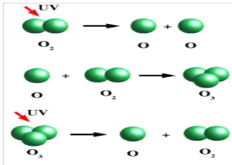
ORMATION OF OZONE LAYEROzone is a gas found in the atmosphere consisting of three oxygen atoms: O3. Ozone is formed in the atmosphere when
energetic ultraviolet (UV) radiation dissociates molecules of oxygen, O2 , into separate oxygen atoms. Free oxygen atoms can
Figure: 2. Ozone formation and destruction.
The ozone in the stratosphere is produced by photochemical reactions involving O2. When diatomic oxygen in the stratosphere
absorbs ultraviolet radiation with wavelengths less than 240 nm, it breaks apart into two oxygen atoms.
O2(g) 2O(g) (light wavelength < 240 nm) (1)
The resulting oxygen atoms combine with O2 molecules to form
ozone.
O(g) + O2(g) O3(g) (2)
This reaction is exothermic, and the net effect of the previous two reactions is the conversion of three molecules of O2 to two
molecules of ozone with the simultaneous conversion of light energy to heat. Ozone absorbs ultraviolet radiation with wavelengths as long as 290 nm. This radiation causes the ozone to decompose into O2 molecules and oxygen atoms.
O3(g) O2(g)+(g) (light wavelength <290nm)(3)
This, too, is an exothermic reaction. The overall effect of this reaction and the previous reaction is the conversion of light energy into heat. Thus, ozone in the stratosphere prevents highly energetic radiation from reaching the Earth's surface and converts the energy of this radiation to heat. Rain water is never always pure as it contains impurities from dust particles or from absorbing gases from the air. It forms when clean rain comes in contact with pollutants like ozone (O3), sulphur Dioxide (So2),
Carbon Dioxide (Co2), and Nitrogen dioxide (NO2). The major
oxide that contributes to the formation of ozone layer depletion is ozone. Ozone is produced in the high temperatures of combustion chambers of power stations and motor vehicles [7].
Ozone also oxidizes nitricoxide to nitrogendioxide:
NO+ O3→ NO2 + O2 (4)
This reaction is accompanied by chemiluminescience .The NO2 can be further oxidized:
NO2 + O3→NO3 + O2 (5)
The NO3 formed can react with NO2 to form N2O5: Solid nitronium perchlorate can be made from NO2, ClO2,
and O3 gases:
2 NO2 +2ClO2 +2 O3 →2NO2ClO4 + O2 (6)
Sulfuric acid can be produced from ozone, water and either elemental sulfur or sulfur dioxide:
S + H2O + O3→ H2SO4 (7)
3 SO2 + 3 H2O + O3→ 3 H2SO4 (8)
Nitrogen oxides (NO) are formed through fossil fuel use. In contrast to sulphur, nitrogen is not an impurity but rather an integral part of the organic material making up fossil fuels. Fossil fuel combustion releases nitrogen into the atmosphere, usually in the form of nitric oxide (NO). Nitric oxide (NO) is oxidized by atmospheric molecules, such as ozone (O3) or hydrogen dioxide (HO2), to form nitrogen dioxide (NO2). Nitrogen dioxide (NO2) reacts with OH in the atmosphere to form nitric acid (HNO3). Nitric acid can also form when nitrogen dioxide (NO2) reacts with the nitrate radical (NO3) in the presence of atmospheric water or aldehydes. These pollutants can be converted, through a series of complex chemical reactions, into sulphuric acid, nitric acid,
increasing the ozone precipitation and other precipitation such as snow and fog and the formation of ozone layer depletion is shown in Fig.3.
Fig: 3. Formation of ozone layer Depletion
The pH scale ranges in values from 1 to 14. The pH scale is used to indicate the nature of the substance as shown in Fig. 3. When pH is below 7, it is ozone layer depletion and no ozone layer depletion when pH is above 7[7]. Any substance with a pH value 7 is considered a neutral substance. This means that the substance is neither ozone nor no ozone. Precipitation is considered as ozone precipitation if it has a pH of less than or equal to 5.
IV.
E
XPERIMENTALM
ETHODOLOGYThe goal of this processing is to examine the satellite images and tell whether the gathered satellite image is an ozone image or not. The overall process involved is shown in Fig.4. In this implementation satellite images containing O3 emissions are taken as input, which may or may not contain noise. But any satellite images most probably may contain noise which is to be removed. There are different types of noise in satellite images such as speckle noise, blurs and so on. When a satellite image containing such types of noise is analyzed, the value obtained may deviate from original value. Hence, the image must be de noised.
As an original image may contains various textures these textures are to be separated to obtain the region of interest and exclude the non affecting region for ozone layer depletion prediction. In order to segment the image and capture the region of interest, k-means clustering [8-10] is used as one of the technique. Pixel values of different textures are used for this segmentation which is shown in Table 1. Based on these pixel values the satellite image is segmented into various clusters to obtain the region of interest which is containing ozone. In order to predict the occurrence of ozone layer depletion at higher range k-means algorithm is used to cluster the objects into 8 regions and ozone emission objects into 8 regions using Euclidean distance metric to avoid local minima.
Figure: 4. Real time detection of ozone layer depletion
In order to predict the occurrence of ozone layer depletion the mean wavelength (µ) is to be estimated from the feature extracted image using MATLAB 2011a Tool. Further, other parameters such as number of ozone molecules, grams of ozone and liquid molecules present in ozone gas are to be calculated using equations 1, 2, 3, 4 and 5. As a satellite image is visible image which lies in a wavelength between 400nm-700nm. Since this is taken as input, this range is taken as a total of 300nm and the scale for the input satellite image is given as 2 Dobson units. According to the study 1nm consists of 0.0067 Dobson units and has a constant value of 2.69 x 10²⁰ molecule/m2 [11]. To calculate the
number of ozone molecules equation 1 is used and is shown below. Avogadro’s number 6.023 x 10²³ mol-1 is a quantity of
mole which is used to calculate the number of atoms present in the substance.
mole a of Quantity
x x x O of Area Molecules Ozone
20 3 0.0067 2.69 10
= (9)
The expression to calculate the grams of O3 is shown below:
2 3
3
so of weight Molecular x
molecules Ozone x O of
O of Grams
μ
= (10)
Where, Molecular weight of so2is 63.066 g/mol.
The Liquid molecules present in humidity image are computed by using equation 3.
2 2 2
O of Valence
O H of weight Molecular x
molecules Ozone
x O H of
Molecules Liquid
μ
=
(11)
Where, Molecular weight of H2O is 18 and Valence of Oxygen is 2.
From equation 3, the amount of liquid present in the ozone gas can be analyzed by using the specific gravity of water i.e., 1.003 liters.
water of gravity Specific
Molecules Liquid
solution of
Liters =
(12)
Normality is a way of expressing the concentration of a solution. The normality of a solution is the concentration expressed as the number of equivalent weight of solute per liter solution. Where, Equivalent weight of Solute HNO3 is 63 grams.
solution of Liters x solute of weight Equivalent
solute of Grams Normality=
(13) Since, it is a monoprotic the normality is used as a measure of reactive species in solution. In chemistry, normality is used to express the concentration of protons (H+). Hence,
Normality=
[ ]
H+ions. (14)To measure the ozone of a solution pH value is considered which is defined as negative logarithmic value of a hydrogen ion H+ concentration. This pH value is also included with a correction
factor as shown in equation 6.
[ ]
(
)
{
logH x10 14}
pH= − + − (15)
Figures: 5. Original image of water vapour(h2o)
Figure:6. Original image of ozone(o3)
Figure: 7. Clustered image of h2o
Figure: 8. Clustered image of Ozone
V. E
XPERIMENTALR
ESULTSIn the present research, the problem is extensively studied on 300 ozone images and examined on 200 images obtained from Japan metrological department to estimate the ozone at Australia location. The pH values on a sample of 10 ozone layer depletion images are tabulated in Table I.
Estimating mean wavelength and area of ozone in ozone image and mean of water vapour in h2o image is one of the challenging
detection of ozone layer depletion from satellite images is even more challenging as the images are always covered with different textures. A lot of research has been performed on the development of accurate techniques for the prediction of ozone layer depletion. But, these techniques are unable to perform up to their true extent.
The preliminary results in Table II show that the pH of the ozone images is in the range of 1 and 5. Consider image 1, its calculated pH value is 4.39, lies in the established range, hence it is ozone layer depletion. In the similar method, consider the other images and their calculated pH value are in between 1 and 5 which lies in the established range and hence they are ozone layer depletion. From Table II, consider image 4, its calculated pH value is 5.97, which doesn’t lie within the range, hence it is not ozone layer depletion. Similarly, consider image 5 whose
calculated pH value is 2.39, lies in the range 1 and 5 hence it is an ozone layer depletion image. Consider image 29 whose calculated pH values is 4.60, lies in the range 1 and 5 hence it is an ozone layer depletion image. Consider image 39, whose calculated pH value is 4.82, lies in the established range for ozone layer depletion. Hence, it is an ozone layer depletion image. As the recognition of ozone layer depletion obtained from the present research is more than previous model, the proposed model proves to have more potential.
As the recognition of ozone layer depletion obtained from the present research is more than previous model, the proposed model proves to have more potential.
TABLE I: Estimation Of PH In Precipitation
Image no. Mean of
Ozone
Mean of H2O
Area of ozone
Grams of Ozone
Ozone Molecules
Liquid Molecules
Litres of
solution Normality ph value
Image 1 107.87 79.0515 75786 1.5428x 10⁴ 2.2678 1.6135x 10³ 1.6086 x 10³ 0.1522 4.8232 Image 2 110.26 60.3465 80204 1.6690 x 10⁴ 2.4000 1.3035 x 10³ 1.2996x 10³ 0.2039 1.9037 Image 3 107.20 123.5297 78070 1.5794x 10⁴ 2.3361 2.5972 x 10³ 2.5895x 10³ 0.0968 9.3495 Image 4 110.52 87.33540 78972 1.6472x 10⁴ 2.3631 1.8575x 10³ 1.8591 x 10³ 0.1412 5.5770 Image 5 114.20 129.2997 96520 2.0802x 10⁴ 2.8882 2.6630x 10³ 2.6550x 10³ 0.1244 6.8454 Image 6 108.36 108.9999 62995 1.2883x 10⁴ 1.8850 1.8492x 10³ 1.8437x 10³ 0.1109 7.9901 Image 7 107.09 139.0542 66920 1.3525 x 10⁴ 2.0025 2.5061x 10³ 2.4986 x 10³ 0.0859 10.5435 Image 8 116.91 100.9331 71281 1.5727x 10⁴ 2.1330 1.9376x 10³ 1.9318x 10³ 0.1292 6.4621 Image 9 117.96 65.15950 101972 5.4806x 10⁴ 3.0514 1.7894 x 10³ 1.7841 x 10³ 0.2020 1.9961 Image 10 100.47 107.6880 110257 2.0906x 10⁴ 3.2993 3.1976 x 10³ 3.1881x 10³ 0.1041 8.6250
TABLE II: Analysis of ozone layer depletion
Image No. Observed Normality PH value Experimental Prediction
Image 1 Depletion 0.1589 4.394 Depletion TRUE
Image 2 Depletion 0.2103 1.5922 Depletion TRUE
Image 3 Depletion 0.1918 2.5122 Depletion TRUE
Image 4 Depletion 0.1356 5.979 No Depletion FALSE
Image 5 Depletion 0.1942 2.3905 Depletion TRUE
Image 6 Depletion 0.157 4.5128 Depletion TRUE
Image 7 Depletion 0.1281 6.546 No Depletion FALSE
Image 8 Depletion 0.1422 5.5025 No Depletion FALSE
Image 9 Depletion 0.1002 9.0031 No Depletion FALSE
Image 10 Depletion 0.0969 9.3454 No Depletion FALSE
Image 11 Depletion 0.1272 6.6196 No Depletion FALSE
Image 12 Depletion 0.1031 8.7169 No Depletion FALSE
Image 13 Depletion 0.109 8.1639 No Depletion FALSE
Image 14 Depletion 0.1077 8.2798 No Depletion FALSE
Image 15 Depletion 0.0922 9.7331 No Depletion FALSE
Image 16 Depletion 0.1522 4.8232 Depletion TRUE
Image 17 Depletion 0.1831 2.9762 Depletion TRUE
Image 18 Depletion 0.1412 5.577 No Depletion FALSE
Image 19 Depletion 0.1244 6.8454 No Depletion FALSE
Image 20 Depletion 0.0733 12.1299 No Depletion FALSE
Image 21 Depletion 0.1109 7.9901 No Depletion FALSE
Image 22 Depletion 0.1237 6.8985 No Depletion FALSE
Image 23 Depletion 0.1357 5.9725 No Depletion FALSE
Image 24 Depletion 0.1385 5.7711 No Depletion FALSE
Image 25 Depletion 0.1186 7.3205 No Depletion FALSE
Image 26 Depletion 0.1291 6.4696 No Depletion FALSE
Image 27 Depletion 0.1222 7.0179 No Depletion FALSE
Image 28 Depletion 0.1239 6.8834 No Depletion FALSE
Image 29 Depletion 0.1555 4.6088 Depletion TRUE
Image 30 Depletion 0.0859 10.5435 No Depletion FALSE
Image 31 Depletion 0.1146 7.6625 No Depletion FALSE
Image 32 Depletion 0.1292 6.4621 No Depletion FALSE
Image 33 Depletion 0.2039 1.9037 Depletion TRUE
Image 34 Depletion 0.1638 4.0894 Depletion TRUE
Image 35 Depletion 0.202 1.9961 Depletion TRUE
Image 36 Depletion 0.0968 9.3495 No Depletion FALSE
Image 37 Depletion 0.1 9.0225 No Depletion FALSE
Image 38 Depletion 0.1166 7.4908 No Depletion FALSE
Image 39 Depletion 0.1522 4.8287 Depletion TRUE
VI. C
ONCLUSIONIn this paper, we presented a methodology to find ozone layer depletion in precipitation using ozone imagery. This problem is addressed for the first time which is computationally efficient and adapt to as well with respect to measured pH value. Ozone depletion gets worse when the stratosphere (where the ozone layer is), becomes colder. Because global warming traps heat in the troposphere, less heat reaches the stratosphere which will make it colder. Greenhouse gases act like a blanket for the troposphere and make the stratosphere colder.
Due to this, prediction of ozone layer depletion has become a major concern and this study investigated the risk of ozone layer get depleted from precipitation and ozone satellite imagery. Clustering and finding mean wavelength (µ), area of clustered
image are used as one of the efficient technique for the prediction purpose. A more detail study on the data is planned to incorporate estimation of ozone in other places, however the present method became a base for future research.
R
EFERENCES[1] Allied Signal Corporation. “Remarks,” International CFC and Halon Alternatives Conference. Washington, DC.1989.
[2] Alternative Fluorocarbons Environmental Acceptability Study (AFEAS), Washington, DC, 1995.[3] “Production, Sales, and Atmospheric Release of Fluorocarbons,” Alternative Fluorocarbons
Environmental Acceptability Study (AFEAS), Washington, DC 1996.
[3] Morrisette, Peter M. "The Evolution of Policy Responses to Stratospheric Ozone Depletion".Natural Resources Journal, vol. 29, 1995.
[4] Stephen O., E. Thomas Morehouse, Jr., and Alan Miller, “The Military’s Role in Protection of the Ozone Layer.” Environmental Science and Technology, vol 28, no. 13, 1994.
[5] J. J. Margitan. “H2O in the Stratophere: 3 Insitution Observations,”
Geophysical Research Letters, vol. 8, no. 3, 1991.
[6] H.Mrose, “Measurements of pH, and chemical analyses of rain, snow, and fog water,” Metrological Observatory, Dresden-Wahnsdorf, Vol 18, 1966.
[7] Anil Z Chitade and DR.S.K.Katiyar, “Colour based image segmentation using K-means clustering,”International Journal of Engineering Science and Technology, Vol.2, 2010.
[8] K.Somasundaram and N.Kalaichelvi, “Feature identification in Satellite images using K-means segentation,” National Conferences on signal and image processing, 2012.
[9] Balasubramanian Subbiah and Seldev Christopher.C, “Image Classification through intergraed K-means Algorithm,” The International Journal of Computer Science Issues, Vol.9, 2012.