Fuzzy Controlled DFIG WIND System with Battery for Low and High Frequency
Components in Generation system
MUGADA HARISH KUMAR U ANJAIAH
M.tech Student Scholar
T. SRINIVASA RAO
Associate Professor Assistant Professor
Avanti Institute of Eng &Technology Avanti Institute of Eng & Technology Avanti Institute of Eng &Technology
ABSTRACT
Over the past 20 years the concern over renewable energy resources is increasing due to limited conventional resources and increased pollution. In India, 16.8 % of power is contributed by wind energy and with the technological advances there is a good scope of increasing the power contributed by wind energy. However, the wind generators when integrated to the grid have adverse effects which lead to the reduction in power quality. Many researchers have proposed different techniques to maintain the voltage quality at the PCC by controlling the reactive power. Instead of controlling the reactive power, an energy storage system can be used to control the voltage .A control strategy for managing the demand – generation fluctuations using a hybrid energy storage system in a wind‐dominated remote area power supply system consisting of a DFIG, a battery storage system, a super capacitor, a dump load and main loads. Operation of battery storage system is coordinated with a super capacitor with a view to improving the performance of the battery. In this regard, the battery storage system is connected to the load side of the RAPS system, whereas the super capacitor is connected to the dc bus of the back – to – back converter of the DFIG. The project emphasizes on the application of hybrid energy storage systems to mitigate the effect of wind speed fluctuations with fuzzy controller, thereby ensuring smooth power output as well as improving the power quality at the PCC.
Index Terms: Transient Stability, DFIG, RAPS system, and Wind power, Fuzzy etc.
1.
INTRODUCTIONElectricity is identified as onekey commodity which can be used as a medium for economic growth in rural and regional areas. According to ministry of new and renewable energy, country's present installed power generation capacity has more than doubled to 2, 34,600 MW in the past 10 years. Renewable energy contributes to nearly 34351.39 MW to the total generating capacity and in which wind energy contributes 20149.5 MW. Even though we have 20149.5 MW of installed capacity, India faces an outage of more than 30000 MW due to increase in demand. This shortage can be reduced by use of renewable energy, since renewable energy is reliable, abundant and will potentially be very cheap once the technologyimprove
1.1 HYBRID ENERGY STORAGESYSTEM
An ideal energy storage in a standalone wind energy conversion system should be able to provide both high energy and power capacities to handle situations such as wind gusts and load step changes, which may exist for seconds or minutes or even longer. At present, various types of storage technologies are available to full fill either power or energy requirements of a RAPS system. Widely used energy storage technologies that currently employ in wind farms are batteries, super capacitors, fly wheels, compressed‐air energy storage, hydro pumped storage, superconducting magnetic energy storage, fuel cells, etc. Hybrid energy storage system is a system which consists of a battery and a super capacitor which are comparativelbest when compared other storing device. Among all
energy storage systems, batteries are seen to have one of the highest energy density levels i.e., it is able to store for longer periods, whereas the supercapacitors seem to have the highest power density i.e., they are able to handle transients that occur over short period of time. At present, battery storage systems are widely employed in most real – life RAPS applications. To further improve the performance of the battery energy storage systems, a supercapacitor can be incorporated to perform a hybrid operation. In this way, the combined energy storage system is able to satisfy both power and energy requirements of the RAPS system. A power management algorithm is designed in such a way that the supercapacitor should be able to absorb the ripple component of demand – generation mismatch leaving the steady component for the battery storagesystem.
In this paper design and development of wind dominated RAPS system to maintain the load side voltage and frequency within acceptable limits during over – generation and under – generation. To achive this main objective, it is important to manage the active and reactive power contribution of the components of the RAPS system. In this regard, control coordinated strategies are developed and implemented among the components present within the RAPS system. In addition, individaul control is developed based on an appropriate coordinated control approach with a view to regulate the magnitude of the voltage and freqency on the load side. In this thesis, RAPS system consisting of battery storage, super capacitor and dump load along with wind turbine generator as the main component areconsidered.
2. DFIG OPERATION ANDCONTROLLING
2.1OPERATING OF THEDFIG
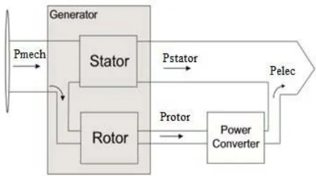
In this thesis, DFIG is given much importance because it feds ac currents into both the startor and the rotot windings. The primary advantage of DFIG when compared to other generators is that when used in wind turbines they allow the amplitude and frequency of their output voltage to be maintained at a constant value, no matter the speed of wind blowing on the wind turbine rotor. A typical configuration of a DFIG based wind turbine generator system is shown inFig.2.1
Figure 2.1: DFIG based wind turbine generator system The operation of which can be categorized into two modes: (a) super – synchronous and (b) sub – synchronous. The difference between operations of these twomodescanbedeterminedfromtherotor ,
compared to the synchronous , and the direction of power flowing through the back – to – backconverter.
In the super – synchronous mode, the rotor speed of the DFIG is kept above synchronous speed leading to a negative slip s < 0, as evident from Eq. (2.1). During the super – synchronous mode, the generated wind power passes to the load through the stator, as well as through the rotor, of the DFIG which is given by Eq.(2.2) and (2.3) respectively (i.e., Pr > 0) as shown in Fig.2.2
Figure 2.2: Super – synchronous mode of operation
(2.1)
(2.2)
(2.3)
In contrast, during the sub – synchronous mode of operation, the rotor speed is kept below the synchronous speed. The generated wind power is supplied to the load by the stator while slip power is absorbed through the rotor (i.e., Pr < 0) as shown in Fig.2.3.
Figure 2.3: Sub – synchronous mode of operation 2.2. ROTOR SIDE CONVERTER CONTROL
As shown in Fig.3.5, the RSC controller consists of inner – loops which have fast field oriented current control and the slow outer – loops that generate the reference currents for the inner loops.
Figure 2.4: RSC control scheme
The voltage controller of the DFIG is developed using a reactive power based control approach. In this regard, the total stator reactive power output Qs, of DFIG given in Eq.(2.4)
(2.4)
power components of these two currents, namely: Qmag and Qgen are given by Eq. (2.5) and Eq. (2.6) respectively.
(2.5)
(2.6)
2.3 LINE SIDE CONVERTER CONTROL
The LSC is used to control the DC bus voltage of the back – to – back converter system and to supply any reactive power to the loads if needed
Figure 2.5: LSC control scheme
The d and q axes components of currents through filter can be used to regulate the DC link voltage and reactive power supply to the loads respectively. Although there is a possibility of supplying reactive power through LSC similar to a static synchronous compensator (STATCOM), in the present work, the reactive power reference Qref is set at zero. The corresponding control scheme implemented for LSC is shown inFig.2.5.
Rotor side converter and Line side converter operation was also explained along with their controlling schemes. The controlling implemented is flux oriented vector control and Pitch angle controlling
3. PROPOSED MODEL OF RAPSSYSTEM
The configuration of the DFIG based RAPS system consisting of the hybrid energy storage and dump load with main loads is shown in Fig3.1.The battery storage is connected to the load side using an inverter whereas the super capacitor is interfaced to the DC bus of the back – to – backconverter system by means of a bi –directional buck boostconverter.
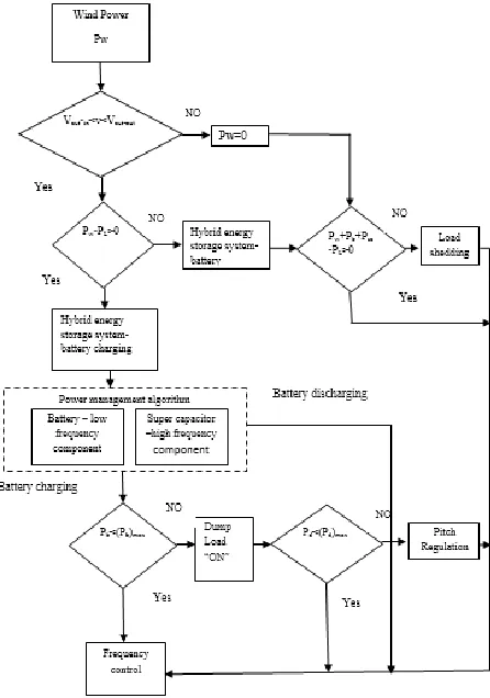
The operation of the entire RAPS system is designed according to the coordinated control approach and The decision – making process associated with the control coordination algorithm of the wind – battery – supercapacitor – based RAPS system given in Fig 3.2
Figure 3.1: Proposed model of DFIG based RAPS system
Figure 3.1: A Coordinated control approach for hybrid energy storage based RAPS system
During over generation condition where the power output from the wind turbine generator Pw is greater then the load demand PL, the hybrid energy storage Pb (i.e., battery storage and super capacitor) absorbs the excess power (PW – PL ) and is shared between the battery storage system and super capacitor according to the power management algorithm. If the capacity of the hybrid energy storage system reaches the maximum limit or (Pb) max, the dump load needs to absorb the excess power. However, if the dump load power Pd reaches its maximum limit rating (Pd) max, the pitch angle control has to be activated in order to reduce the power output of the wind turbine generator.
During under generation situations where the power output of the wind turbine generator is less than the load demand, i.e., (PW – PL )< 0, it is assumed that the hybrid energy storage Pb is able to supply the required power deficit (PL – PW).
During emergency situations such as no power output from wind turbine generator due to wind speed being below cut – in level or above cut – out level, a load shedding scheme can be implemented. Moreover, the proposed control coordination concept has been realized by developing the control strategies for each component of the RAPSsystem.
4. SIMULATION MODELS ANDRESULTS
4.1BATTERY AND SUPER CAPACITORRESULTS -- Time
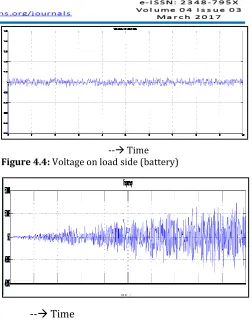
Figure 4.4: Voltage on load side (battery)
Figure 4.2: Simulation circuit with battery and super capacitor
The simulation model with Battery and super capacitor is designed presented above in fig4.1.
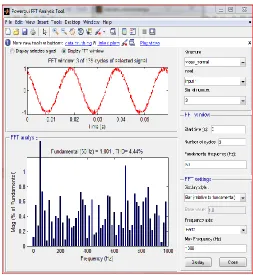
The system response of the DFIG based RAPS systemwith battery and super capacitor as hybrid storage system is shown in below The FFT analysis of the battery current is shown to be free from ripples or high – frequency component which is presented in Fig 4.6. The operating frequency of the RAPS system is shown in Fig.4.5. The operating frequency is closely regulated at its rated value of 50 Hz and is seen not to be influencedby the wind speed or load step changes. Furthermore, it can be seen that the frequency of the system is maintained within 0.2% of its rated value.
--
Time
Figure 4.5: Frequency on load side (battery)
Figure 4.6: FFT analysis of the battery system
-- Time
Figure 4.3: Wind speed (battery)
The voltage on load side is shown in Fig.4.4 which not to be affected by the wind speed or load changes. This proves that the DFIG controllers are able to maintain voltage constant. The load voltage of the system stays 1 Pu (± 2% of its rated value) throughout the operation.
--
Time
Fuzzy logic is a new control approach with great potential for realtimeapplications.
Fig4.1 shows the structure of the fuzzy logic controller (FIS-Fuzzy inference system) in MATLAB Fuzzy logic toolbox. .Load voltage and load current taken as input to fuzzy system. For a closed loop control, error input can be selected as current, voltage or impedance, according to control type. To get the linearity triangular membership function is taken with 50% overlap. The output of fuzzy controller taken as the control signal and the pulse generator provides synchronous firing pulses to thyristors as shown in fig 4.2 The Fuzzy Logic is a rule based controller, where a set of rules represents a control decision mechanism to correct the effect of certain causes coming from power system. In fuzzy logic, the five linguistic variables expressed by fuzzy sets defined on their respective universes of discourse. Table-I shows the suggested membership function rules of FC-TCR controller. The rule of this table can be chosen based on practical experience and simulation results observed from the behavior of the system around its stable equilibriumpoints.
Fig 4.8 Structure of fuzzy logic controller
Load volta g e
Load curre n t
NL N
M P PM PB NL PB PB N
M M N N L NM PB PB N
M P N L P P PM N
M M N P
PM N
M P M N M N M P PB NL N
M M N NL N L
Fig 4.9FFT for load voltage without FUZZY controller
Fig 4.10 FFT for load voltage with FUZZY controller
5. CONCLUSION
The paper has addressed the benefits of integrating a super capacitor to a battery storage system in a wind – based hybrid RAPS system. Through simulation studies it can be concluded that RAPS systems was capable in maintaining the constant voltage and frequency at the load end. Also, it has been noted that the power sharing between the systems components were accomplished in accordance with the proposed coordinated control methodology.
When considering the operation of battery storage systems, avoidance of heavy DOD rates and reduced ripple content in the battery current is given importance. To solve above problem, a super capacitor was integrated with the battery storage system to form the hybrid energy storage (i.e. battery and super capacitor) and improving battery’s performance. Furthermore, it has also been noted that the super capacitors integrated to the DFIG was able to handle the transients caused by wind speed and load changeseffectively.
Thus concluding by saying that the hybrid operation of the RAPS systems were capable in maintaining the voltage and frequency at the load end with proper power sharing between thedevices
As extensions to the work presented in this paper, following is a description of further activities that can be undertaken in relation to standalone RAPS system: Development of the control strategies for each component of RAPS systems with a view to operate them under unbalanced loadconditions.
Providing protection to thesystem.
Integration of other types of renewable energy systems (e.g. solar photovoltaic) to wind based RAPS systems.
Further development of the existing control strategies of the RAPS systems to operate as a grid interactive micro – grid.
REFERENCES
[1] N. Mendis, K. M. Muttaqi “Management of Low‐ and High‐Frequency Power Components in Demand‐ Generation Fluctuations of a DFIG‐Based Wind‐ Dominated RAPS System Using Hybrid Energy Storage,” IEEE Transactions on Industry Applications, Vol. 50, No. 3, May/June 2014.
[2]Doubly fed induction generator system for wind turbine by S. MÜLLER, M. DEICKE, & RIK W. DE DONCKER
May/June 2011.
[3] P. F. Ribeiro, B. K. Johnson, M. L. Crow, A. Arsoy, and Y. Liu, “Energy storage systems for advanced power applications,” Proc. IEEE, vol. 89, no. 12, pp. 1744–1756, Dec. 2001.
[4]M.Beaudin, H.Zareipour, A.Schellenberglabe, and W.Rosehart, “Energy storage for mitigating the variability of renewable electricity sources: An updated review,” Energy Sustainable Develop., vol. 14, no. 4, pp. 302– 314, Dec. 2010.
[5] T. Patrick and Moseley, “Energy storage in remote area power supply (RAPS) systems, “J.PowerSources, vol.155, no.1, pp.83–87, Apr.2006.
[6] W. Li, G. Joos, and J. Belanger, “Real‐time simulation of a wind turbine generator coupled with a battery super capacitor energy storage system,” IEEE Trans. Ind. Electron., vol. 57, no. 4, pp. 1137–1145, Apr. 2010.
[7] P. Thounthong, S. Rael, and B. Davat, “Control strategy of fuel cell and supercapacitors association for a distributed generation system,” IEEE Trans. Ind. Electron., vol. 54, no. 6, pp. 3225–3233, Dec. 2007.
[8]S. Bhattacharyya (ed.), Rural Electrification through Decentralized Off‐grid Systems in Developing Countries, Green Energy and Technology, DOI: 10.1007/978‐1‐4471‐ 4673‐5_2, Springer‐Verlag London 2013.
[9] John Fletcher and Jin Yang (2010). Introduction to the Doubly‐Fed Induction Generator for Wind Power Applications, Paths to Sustainable Energy, Dr Artie Ng (Ed.), ISBN: 978‐953‐307‐401‐6, Intec, Available from:
http://www.intechopen.com/books/paths‐to sustainable‐energy/introduction‐to‐the‐doubly‐fed‐ inductiongenerator‐for‐wind‐power‐applications
[10] D. Santos‐Martin, S. Arnaltes, and J. L. R. Amenedo. Reactive power capability of doubly fed asynchronous generators. Journal of Electric Power Systems Research, 78(11):1837 – 1840, Nov. 2008.
[11] KrisztinaLeban. Doubly Fed Induction Generator Fault Simulations.PhD thesis, Institute of Energy Technology, Aalborg University, Alborg, Denmark, 2009.
Mr. MUGADA HARISH KUMAR Is an M.Tech scholar at Avanthi Institute of Engineering & Technology under JNTU Kakinada. He received B.tech Degree from
Swarandhra Engineering College under JNTU
Kakinada.His current research interests mainly Power Electronics.
Mr.T.SRINIVASA RAO is an Associate Professer and Head of the Department in Avanthi Institute of
Enginnering & Technology,Visakhapatnam. He is
currently working towards Ph.D.He got His M.tech Degree from GITAM University.His current research intersts are Power Systems and Power System Analysis srinivasarao_tegala@yahoo mail.com
Mr.U.ANJAIAH is an Assistant Professor in Avanthi
Institute of Enginnering & Technology,Visakhapatnam. He got His M.tech Degree from JNTU Kakinada. He received B.tech Degree from Akula Gopayya College Of Engineering & Technology. His current research intersts are High Voltage Engineering.