IJEDR1502137
International Journal of Engineering Development and Research (www.ijedr.org)766
Establishment of MIL-STD-1553B Communication
between Navigation System and Ground System on
Ubuntu Platform
1
Sankarshan Vemuganti, 1B.Tech,
Electrical Communication Engineering,
1Sree Visvesvaraya Institute of Technology & Science , Mahabubnagar, India
________________________________________________________________________________________________________
Abstract - Inertial Navigation System is the dead reckoning navigation system, by which present position may be calculated from knowledge of initial position and measurements of speed and direction. An Inertial Navigation System uses inertial sensors - gyroscopes and accelerometers – to sense rotational and translational motion with respect to a reference frame. Inertial navigation is the process whereby the measurements provided by gyroscopes and accelerometers are used to determine the position of the vehicle. By combining the two sets of measurements, it is possible to define the translational motion of the vehicle within the reference frame and so to calculate its position within it.MIL-STD-1553B is a military standard that defines the electrical and protocol characteristics for the exchange of data and information between various systems in bus configuration. Any MIL-STD-1553B system should be in either Bus Controller or Remote Terminal mode to communicate with other MIL-STD-1553B systems in the bus configuration. One MIL-STD-1553B system should be in Bus Controller mode or the remaining MIL-STD-1553B systems should be in Remote Terminal mode for exchange of information in bus configuration. To communicate the navigation system with the ground system, navigation system is configured as Remote Terminal and ground system is configured as Bus Controller. The project is to implement the software which should establish MIL-STD-1553B communication between navigation system and ground system on Ubuntu platform with Eclipse IDE.
Index Terms - Inertial Navigation System, Gyroscopes, Accelerometers, Communication
________________________________________________________________________________________________________
I. INTRODUCTION
MIL-STD-1553 is a military standard that defines the electrical and protocol characteristics for a data bus. A data bus is used to provide a medium for the exchange of data and information between various systems. It is similar to what the personal computer and office automation industry has dubbed a Local Area Network (LAN).
This guide provides an introduction to the MIL-STD-1553 data bus, its history, applications, and use. It describes: 1) The physical elements that make up the bus.
2) The protocol, including the message formats, word types, and command and status words.
3) Status word bits and mode commands and their definitions and use, both from the remote terminal and bus controller perspective.
4) Issues such as bus loading, major and minor frame timing, and error recovery.
DDC provides an assortment of quality MIL-STD-1553 commercial, military, and COTS grade cards and components to meet your data conversion and data interface needs. DDC supplies MIL-STD-1553 board level products in a variety of form factors including AMC, USB,PCI, cPCI, PCI-104, PCMCIA, PMC, PC/104, PC/104-Plus, VME/VXI, and ISAbus cards. Our 553 data bus board solutions are integral elements of military, aerospace, and industrial applications. Our extensive line of military and space grade components provide MIL-STD-1553 interface solutions for microprocessors, PCI buses, and simple systems. Our 1553 data bus solutions are designed into a global network of aircraft, helicopter, and missle programs.
The primary purpose of the data bus is to move data between black boxes. How these boxes are connected and the methodology with which the communication is accomplished is central to the operation of the data bus.
II. BUS CONTROLLER
The bus controller is responsible for directing the flow of data on the data bus [1]. There are three types of bus controller architectures:
IJEDR1502137
International Journal of Engineering Development and Research (www.ijedr.org)767
1. WORD CONTROLLER:A word controller is the oldest and simplest type of controller. Few word controllers are built today. For a word controller, the terminal electronics transfers one word at a time to the subsystem. Message buffering and validation must be performed by the subsystem. This places quite a burden on the subsystem due to the timing requirements of the bus.
2. MESSAGE CONTROLLER:
Today, many of the “fielded” bus controllers are message controllers. These controllers output a single message at a time, interfacing with the computer only at the end of the message or perhaps when an error occurs. Some message controllers are capable of performing minor error processing, such as transmitting once on the alternate data bus, before interrupting the computer.The computer informs the interface electronics where the message exists in memory and provides a control word. For each message, the control word typically informs the electronics of the message type (e.g., a BC or RT-RT command), on which bus to transfer the message,where to read or write the data words in memory, and what to do if an error occurs.
3. FRAME CONTROLLER:
A frame controller is the latest concept in bus controllers. With the advent of microprocessors and Application Specific Integrated Circuits (ASIC's), this type of controller is rapidly becoming the norm. A frame controller is capable of processing multiple messages in a sequence defined by the host computer. The frame controller is typically capable of performing some error processing as defined by the message control word [2]. Frame processors are used to “off load” the subsystem or host computer as much as possible, interrupting only at the end of a series of messages or when an error that it cannot handle is detected.
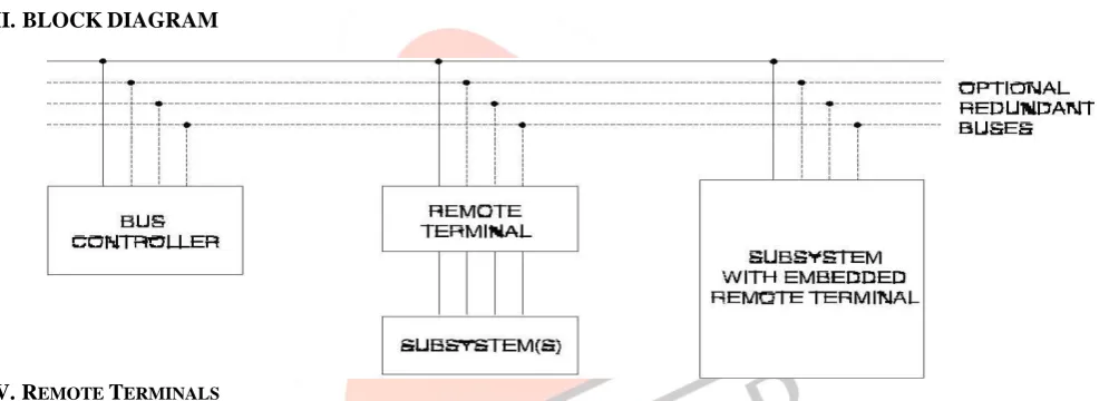
III. BLOCKDIAGRAM
IV. REMOTE TERMINALS
Remote terminals are defined within the standard as “All terminals not operating as the bus controller or as a bus monitor”. Therefore if it is not a controller, monitor, or the main bus or stub, it must be a remote terminal [3]. The remote terminal comprises the electronics necessary to transfer data between the data bus and the subsystem.
V. PROTOCOL-1553B
The rules under which the transfers occur are referred to as “protocol”.The control, data flow, status reporting, and management of the bus are provided by three word types.
Word Types:
Three distinct word types are defined by the standard. These are: 1) Command words.
2) Data words. 3) Status words.
Command Words
IJEDR1502137
International Journal of Engineering Development and Research (www.ijedr.org)768
direction of information flow and is always from the point of view of the remote terminal. A transmit command (logic 1) indicates that the remote terminal is to transmit data, while a receive command (logic 0) indicates that the remote terminal is going to receive data. The only exceptions to this rule are associated with mode commands.The next five bits (bit times 10-14) make up the Sub address (SA)/Mode Command bits.Logic 00000B or 11111B within this field is decoded to indicate that the command is a Mode Code Command. All other logic combinations of this field are used to direct the data to different functions within the subsystem. An example might be that 00001B is position and rate data,00010B is frequency data, 10010B is display information, and 10011B is self-test data[4]. Use of the sub addresses is left up to you; however, Notice 2 suggests the use of Sub address 30 for data wrap-around (defined later).The next five bit positions (bit times 15-19) define the Word Count (WC) or Mode Code to be performed. If the Sub address/Mode Code field is 00000B or 11111B, then this field defines the mode code to be performed. If not a mode code, then this field defines the number of data words to be received or transmitted depending on the T/R bit. A word count field of 00000B is decoded as 32 data words. The last bit (bit time 20) is the word parity bit. Only odd parity is used.Data Word:
The Data Word (DW) contains the actual information that is being transferred within a message. The first three-bit time contains a data sync. This sync pattern is the opposite of that used for command and status words and therefore is unique to the word type. Data words can be transmitted by either a remote terminal (transit command) or a bus controller (receive command). Transmit and Receive, by convention, references the remote terminal [5]. The next sixteen bits of information are left to the designer to define. The only standard requirement is that the most significant bit (MSB) of the data be transmitted first. While the standard provides no guidance as to their use, Section 80 of MIL-HDBK-1553A, Data Word Formats, provides guidance and lists the formats (i.e. bit patterns, resolutions, etc.) of the most commonly used data words. Procurement specifications typically state that Section 80 guidelines should be used in the data word definitions.
Status Word:
A remote terminal in response to a valid message transmits only the status word (SW).The status word is used to convey to the bus controller whether a message was properly received or to convey the state of the remote terminal (i.e., service request, busy, etc.).Since the status word conveys information to the bus controller, there are two views as to the meaning of each bit:
a. What the setting of the bit means to a remote terminal b. What the setting of the bit means to a bus controller.
Each field of the status word, and its potential meanings, is examined below. The status word, with the exception of the remote terminal address, is cleared after receipt of a valid command word. The two exceptions to this rule are if the command word Received is a Transmit Status Word Mode Code or a Transmit Last Command Word Mode Code. Conditions that set the individual bits of the word may occur at any time. If after clearing the status word, the conditions for setting the bits still exists, then the bits is set again. When an error in the data being received is detected, the Message Error bit is set and transmission of the status word is suppressed. Transmission of the status word is also suppressed upon receipt of a broadcast message. For an Illegal Message (i.e. Illegal Command), the Message Error bit is set and the status word is transmitted.
IJEDR1502137
International Journal of Engineering Development and Research (www.ijedr.org)769
There are 3 types of data transferring techniques they are:1) Bus Controller to Remote Terminal 2) Remote Terminal to Bus Controller 3) Remote Terminal to Remote Terminal
Bus Controller to Remote Terminal:
The bus controller to remote terminal (BC-RT) message is referred to as the receive command since the remote terminal is going to receive data [6]. The bus controller outputs a command word to the terminal defining the Sub address of the data and the number of data words it is sending. Immediately (without any gap in the transmission), the number of data words specified in the command word is sent. The remote terminal upon validating the command word and all of the data words issues its status word within the response time requirements (maximum of 12 uSec).The remote terminal must be capable of processing the next command that the bus controller issues. Therefore, the remote terminal has approximately 56 microseconds (status word response time [12 uSec] plus status word transmit time [20 uSec] plus inter-message gap (minimum 4 uSec) plus command word transmit time [20 uSec]) to either pass the data to the subsystem or buffer the data (see Data Buffering).
Remote Terminal to Bus Controller:
The remote terminal to bus controller (RT-BC) message is referred to as a transmit command. The bus controller issues only a transmit command word to the remote terminal. The terminal, on validating the command word, transmits its status word followed by the number of data words requested by the command word [7].The remote terminal doesn’t know the sequence of commands to be sent and doesn’t normally operate on a command until the command word has been validated. Therefore, it must be capable of receiving from the subsystem the data required within approximately 28 microseconds (the status word response time (12 uSec) plus the status word transmission time (20 uSec) minus an amount of time for message validation and transmission delays through the encoder and transceiver).
Remote Terminal to Remote Terminal:
The remote terminal to remote terminal (RT-RT) command allows a terminal (the data source) to transfer data directly to another terminal (the data sink) without going through the bus controller[8]. However, the bus controller may also collect the data and use them. (This is sometimes called a RT-RT-M command, since the Bus Controller monitors the data.)The bus controller issues a command word to the receiving terminal immediately followed by a command word to the transmitting terminal. The receiving terminal is expecting data, but instead of data after the command word it sees a command sync (the second command word).The receiving terminal ignores this word and waits for a word with a data sync.The transmitting terminal ignored the first command word (it did not contain his terminal address). The second word was addressed to it, so it processes the command as a RT-BC command by transmitting its status word followed by the required data words[7].The receiving terminal, having ignored the second command word, again sees a command (status) sync on the next word and waits. The next word (the first data word sent) now has a data sync and the receiving remote terminal starts collecting data[9]. After receipt of all of the data words (and validating), the terminal transmits its status word.Wherever Times is specified, Times Roman or Times New Roman may be used. If neither is available on your word processor, please use the font closest in appearance to Times. Avoid using bit-mapped fonts. True Type 1 or Open Type fonts are required. Please embed all fonts, in particular symbol fonts, as well, for math, etc.
VII. ACKNOWLEDGMENT
We are thankful to DR.TIRUPATHI REDDY, Principal, Sree Visvesvaraya Institute of Technology & Sciences, Mahabubnagar, for his support in carrying out this project.
We wish to acknowledge our gratitude to Sri.B J SUNIL, Professor and Head of the Department of Electronics and Communication Engineering for his support and guidance.
We wish to express our sincere thanks to Sri.D.SATYANARAYANA, Asst.Professor,and project guide, for his constant supervision, personal interest, critical evaluation and inspiring guidance extended by him throughout the duration of the project. It is pleasure to have the opportunity to extend our gratitude to everybody who helped us right from the collection of study material to completion of this project.
REFERENCES
[1] Liang Zhijian, Research and design of 1553b protocol bus control unit, Educational and Network Technology (ICENT), 2010 International Conference.
[2] An Indian perspective of MIL-STD-1553 Bus Protocols, International Journal of Electronic Engineering Research, volume 2 Number 5 (2010).
[3] S. M. Aziz Marko Roessler, A parameter sable vhdl model of an avionics data bus, tencon 2003. conference on convergent technologies for asia-pacific region.
[4] Nimish H.Modi, James R.Armstrong, Joseph G.Tront, Mohammad Ziaullah Khan, Modeling and simulation of 1553 bus for upset tolerance experiments , Computers and communications, 1988. Conference Proceedings. Seventh Annual International Phoenix Conference .
IJEDR1502137
International Journal of Engineering Development and Research (www.ijedr.org)770
[6] Yunhui Yi,Changxing Pei, Nan Chen, Yuan Ren, Changhua Zhu , Research and implementation of high-speed aviation bus , Industrial Electronics and Applications, 2009.ICIEA 2009. 4th IEEE Conference[7] Michael G. Hegarg, High performance 1553: a feasibility study, Data Device Corporation, Bohemia, Ny, IEEE ,Digital Avionics Systems Conference, 2004. DASC 04.
[8] Zhang Yong-xiang Wei-gong Zhang Quan Zhou Rui Ding Yuan-yuan Shang , The design of 1553b communication bus based of bu- 61580 , Industrial Electronics and Applications (ICIEA), 2010 the 5th IEEE Conference