IJEDR1402154
International Journal of Engineering Development and Research (www.ijedr.org)2241
Effective Control Strategy to enhance Power Quality
Improvement using Dynamic Voltage Restorer
1
Ram Hemantkumar Mistry,
2Prof. Hemin D. Motiwala
1 P.G. student, 2 Assistant Professor
Electrical Engineering Department, Sarvajanik College of Engineering & Technology, Surat, India 1[email protected], 2[email protected]
________________________________________________________________________________________________________
Abstract—In 21th century, the expansion of power system and electronic devices has been grown at very fast rate. The most noticeable topic for electrical engineer is Power quality in recent years. Power quality issues is generate due to nonstandard voltage, current or frequency. With Power quality problem utility distribution networks, industrial loads, sensitive loads etc. are suffered. To overcome the problem related to power quality, custom power devices are introduced. A number of power quality solutions are provided by custom power devices. Power quality encompasses several aspects: voltage sags , swells, harmonics, over voltage, flicker, interruptions etc., lasting only a few cycles can cause significant damage for a manufacturing process and computer hardware installations. Now a days , various range of flexible devices introduce for power application. Voltage source converter based Dynamic Voltage Restorer (DVR) can be used effectively for mitigation of voltage sag and swell. This paper presents the operating principle, power circuit topologies, control philosophies and application of DVR for power quality improvement along with systematic review of published literature. The simulation modeling of DVR is carried out component wise and their performances are analyzed using MATLAB software. The simulation shows that the control technique is very effective and yields excellent compensation for voltage sag/swell mitigation.
Index Terms—Dynamic Voltage Restorer (DVR), Power quality problem, Voltage sag and swell, Voltage Source
Converter (VSC), series compensation, control system, sensitive load, simulation.
________________________________________________________________________________________________________
I.INTRODUCTION
The various power quality problems are due to the increasing use of non linear and power electronic loads. Voltage disturbances and harmonics occur due to these loads. Power quality problems can cause malfunctioning of sensitive equipments, protection and relay system. These problems generate different type electrical disturbances and have different effects on different kind of sensitive loads. As a result of this vulnerability, increasing numbers of industrial and commercial facilities are trying to protect themselves by investing in more sophisticate equipment to improve power quality. Voltage magnitude decides the quality of power supply. Voltage sags/swells are highly undesirable for every power consumers and industries. So it is a challenging task to mitigate the voltage sag/swell so that the desired load voltage magnitude can be maintained during the different voltage disturbances. The effect of voltage sag/swell can be very expensive for the customer because it may produce severe damage to equipment and malfunctions. By injection and absorption of voltage and power into distribution system, voltage sag/swell can be mitigated using power electronics based devices, which are known as custom power device [1]. Different method has been proposed to limit the cost causes by voltage sag/swell. One approach to address the voltage sag/swell problem is dynamic voltage restorer (DVR) [2]. It can be used to correct the voltage sag and swell at distribution level. The simulation model is developed using MATLAB SIMULINK in section V and discusses simulation results with different sag/swell conditions. The main objective of this paper is to investigate and proposes a new configuration of DVR in order to develop such device for voltage sag/ swells mitigation in the network. This paper explores an analysis of a novel Dynamic Voltage Restorer along with controller for efficient stabilization and utilization.
II.VOLTAGESAGSANDSWELLS
Voltage sag is defined as decrease in RMS voltage or current to values to between 0.1 to 0.9 per unit for duration of 0.5 cycles to one minute . Voltage swell is defined as an increment in rms voltage or current at the power frequency for durations from 0.5 cycles to 1 minute. Typical magnitudes are between 1.1 and 1.8 up. Swell magnitude is also described by its remaining voltage, in this case, always greater than 1.0 [3].
IJEDR1402154
International Journal of Engineering Development and Research (www.ijedr.org)2242
Fig. 1 Definitions of events by IEEE Std.l159-1995Due to the fact that voltage swells are less common in distribution systems, they are not as important as voltage sags. Voltage sag and swell can cause sensitive equipment (such as found in semiconductor or chemical plants) to fail, or shutdown, as well as create a large current unbalance that could blow fuses or trip breakers[4] [5]. These effects can be very expensive for customers, ranging from minor quality variations to produce downtime and equipment damage.
III.DYNAMICVOLTAGERESTORER
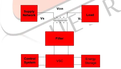
The Dynamic Voltage Restorer (DVR) is a Custom Power Device used to eliminate supply side voltage disturbances. DVR also known as Static Series Compensator maintains the load voltage at a desired magnitude and phase by compensating the voltage sags/swells and voltage unbalances presented at the point of common coupling by connects a voltage source in series with the supply voltage in such a way that the load voltage is kept inside the established tolerance limits [6]. Other than voltage sags and swells compensation, DVR also has added other features like: line voltage harmonics compensation, reduction of transients in voltage and fault current limitations. The main function of the DVR is the protection of sensitive loads from voltage sags/swells coming from the network. The DVR injects the independent voltages to restore and maintained sensitive to its nominal value. The injection power of the DVR with zero or minimum power for compensation purposes can be achieved by choosing an appropriate amplitude and phase angle. The basic structure of a DVR is shown in Fig.1. It is divided into five categories: (i) Voltage Injection Transformers:In a three-phase system, either three single- phase transformer units or one three phase transformer unit can be used for voltage injection purpose. Three single phase injection transformers are connected in delta/open winding to the distribution line. These transformers can be also connected in star/open winding. The star/open winding allows injection of positive, negative and zero sequence voltages whereas delta/open winding only allows positive and negative sequence voltage injection. (ii) Passive Filters:Filters are used to convert the inverted PWM waveform into a sinusoidal waveform. This is achieved by eliminating the unwanted harmonic components generated by VSI action. Higher orders harmonic components distort the compensated output voltage[8].
Supply
Network Load
VSC Energy
Storage
Vs VL
Filter
Control System
VDVR
Fig.2 Basic structure of DVR
IJEDR1402154
International Journal of Engineering Development and Research (www.ijedr.org)2243
energy is drawn from energy storage capacitors. Therefore, there is a minimum voltage required below which the inverter of the DVR cannot generate the require voltage thus, size and rating of capacitor is very important for DVR power circuit. The most important advantage of these capacitors is the capability to supply high current pulses repeatedly for hundreds of thousands of cycles.IV.DVRCONTROLTECHNIQUES
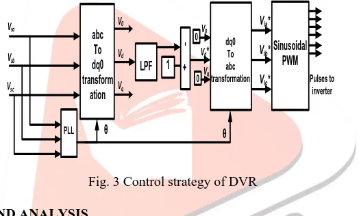
The compensation for voltage sag and swell using a DVR can be performed by injecting/absorbing reactive power or real power[9]. When the injected voltage is in quadrature with the current at the fundamental frequency, compensation is achieved by injecting reactive power and the DVR is self-supported with dc bus. But, if the injected voltage is in phase with the current, DVR injects real power and hence a battery is required at the dc side of VSI. The control technique adopted should consider the limitations such as the voltage injection capability (inverter and transformer rating) and optimization of the size of energy storage. The synchronous reference frame (SRF) theory is used for the control of self-supported DVR[10][12]. The dqo transformation or Park‟s transformation is used to control of DVR. The dqo method expresses the voltage error and phase shift information as instantaneous space vectors with start and end times. The voltage is converted from abc reference frame to d-q-o reference. For simplicity, zero phase sequence components is ignored. The detection of error in voltage is carried out in each of the three phases. The control scheme for the given system is based on the comparison of a voltage that is reference voltage and the measured terminal voltage. The error signal allows generation of a commutation pattern by means of the sinusoidal pulse width modulation technique (SPWM). The injection voltage is generated by difference between the reference load voltage and supply voltage and is applied to the VSC to produce the preferred voltage, with the help of pulse width modulation (PWM)[11]. Fig 3 shows the basic control scheme and parameters that are measured for control purposes. The control algorithm produces a three phase reference voltage to the series converter that tries to maintain the load voltage at its reference value. The d-reference component is set to a rated voltage and the q-reference components are set to zero.
abc To dq0 transform ation PLL LPF V0 Vd Vq dq0 To abc transformation 0
0V0
Vd*
Vq Sinusoidal PWM Pulses to inverter Vsa Vsb Vsc
Via*
Vib*
Vic*
ᶿ
+
1
ᶿ
Fig. 3 Control strategy of DVR
V.SIMULATION RESULTS AND ANALYSIS
A detailed system as shown in Figure 3 has been modelled by MATLAB/SIMULINK to study the efficiency of suggested control strategy. The system parameters and constant value are listed in Table I.
Table 1:System Parameters and Constant
Main Supply Voltage per Phase 415 V
Line Impedance Ls = Rs =
0.01 mH 1.0 Ohm
Line Frequency 50 Hz
Series transformer turns ratio 1:1
DC Bus Voltage 700 V
Filter Inductance 2 mH
Filter capacitance 35 μF
Load P = QL =
1 KW 5 KVAR
IJEDR1402154
International Journal of Engineering Development and Research (www.ijedr.org)2244
CONTROL SYSTEM VSC INJECTING TRANSFORMER Continuous powerguiA B C
Vabc Iabc A B C a b c Vabc Iabc A B C a b c A B C A B C N A B C THREE PHASE VOLTAGE SOURCE
In1 Out1 In1
SWITCHING A B C RL LOAD 1 2 1 2 1 2 Vs Goto6
A B C a b c
FILTER
Fig. 4 Control strategy of DVR i. Voltage Sags
Fig 5(a) shows three phase voltage sag for balance load without DVR. The simulation time is for 1 second. The fault is created for the period of 0.1 sec to 0.2 sec. Fig 5(b) shows three phase load voltage for balance load with DVR and it shows that voltage sag is mitigated by using DVR. Figures 5 (c) shows the voltage injected by the DVR. As a result of DVR performance, the load voltage is maintained at 1 p.u.
(a) Supply Voltage
(b) Load Voltage
(c) Injected Voltage Fig. 5 Balance voltage sag
IJEDR1402154
International Journal of Engineering Development and Research (www.ijedr.org)2245
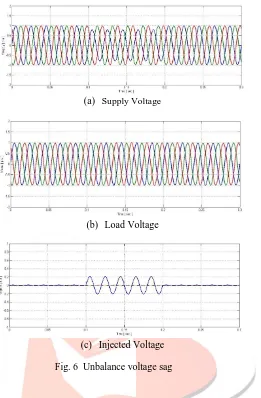
(a) Supply Voltage
(b) Load Voltage
(c) Injected Voltage
Fig. 6 Unbalance voltage sag
ii. Voltage Swell
The second simulation shows the DVR performance during a voltage swell condition. Fig 7(a) shows three phase voltage swell for balance load without DVR. The simulation time is for 1 second. The swell is created for the period of 0.1 sec to 0.2 sec. As observed from this figure the amplitude of supply voltage is increased about 25% from its nominal voltage. Fig 7(b) shows three phase load voltage for balance load with DVR. Figures 7 (c) shows the voltage injected by the DVR. As a result of DVR performance, the load voltage is maintained at 1 p.u. The DVR reacts very quickly in voltage swell condition to inject the appropriate voltage component to correct the supply voltage as in case of voltage sag.
(a) Supply Voltage
IJEDR1402154
International Journal of Engineering Development and Research (www.ijedr.org)2246
(c) Injected VpoltageFig. 7 Balance voltage sag
The effectiveness of the DVR under unbalanced conditions is shown in figure 8, also shows the occurrence of 30% single phase voltage swell on a utility grid. Through simulation the supply voltage with one phase voltage raised to 30% as shown in Figure 8 (a). The DVR load voltage and the injected voltage are shown in Figures 8 (b) and 8 (c) respectively. Its corresponding load voltages are shows that the compensation method is keeping the load voltages constant at 1p.u.
(a) Supply Voltage
(b) Load Voltage
(c) Injected Voltage
Fig. 8 Unbalance voltage swell
VI.CONCLUSION
The simulation model of a DVR using MATLAB/SIMULINK has been presented. A control system based on dqo technique which is a scaled error of the between source side of the DVR and its reference for sags/swell correction has been presented. The simulation shows that the DVR performance is satisfactory in mitigating voltage sags/swells. From simulation results also show that the DVR compensates the sags/swells quickly and provides excellent voltage regulation. The DVR can handles both balanced and unbalanced voltage situations and injects the appropriate voltage component to correct any abnormality in the supply voltage to keep the load voltage balanced and constant at the nominal value.
ACKNOWLEDGMENT
IJEDR1402154
International Journal of Engineering Development and Research (www.ijedr.org)2247
REFERENCES
[1] K.R.Padiyar, “Facts controllers in power transmission and distribution” new age international(P) Ltd publishers, 2007. [2] N.G.Hingorani and L Gyugyi, Understanding FACTS – Concepts and Technology of Flexible AC Transmission
Systems, IEEE Press, New York, 2000.
[3] IEEE Standard Board (1995), “IEEE Std. 1159-1995”, IEEE Recommended Practice for Monitoring Electric Power Quality” IEEE Inc. New York.
[4] C. Alvarez, J. Alamar, A. Domijan Jr., A. Montenegro, and Song, “An investigation toward new technologies and issues in power quality,” in Proc. 9th Int. Conf. Harmon. Qual.
[5] S.F. Torabi, D. Nazarpour, Y. Shayestehfar “compensation of sags and swells voltage using dynamic voltage restorer (DVR) during single line to ground and three-phase faults ” in International Journal “Technical and Physical Problems of Engineering” (IJTPE) , p.p 126-132, September 2012.
[6] Fawzi AL Jowder, “ Modeling and Simulation Of Different System Topologies for Dynamic Voltage Restorer”Electic Power and Energy Conversion Systems, EPECS „O9, International Conference, IEEE,PP, 1-6,2009.
[7] N,G. Hingorani, “ Introducing Custom Power”, IEEE Spectrum, vol. 32,pp.41-48,1995.
[8] H.P. Tiwari and Sunil Kumar Gupta “Dynamic Voltage Restorer against Voltage Sag” International Journal of Innovation, Management and Technology vol. 1, no. 3, pp. 232-237, 2010.
[9] Paisan Boonchiaml, Nadarajah Mithulananthan, Rajamangala University of Technology Thanyaburi Thailand, “Detailed Analysis of Load Voltage Compensation for Dynamic Voltage Restorers” TENCON, IEEE region 10 conference, pp. 1-4, 2006.
[10] H.P. Tiwari and Sunil Kumar Gupta, “Dynamic Voltage Restorer against Voltage Sag” International Journal of Innovation, Management and Technology vol. 1, no. 3, pp. 232-237, 2010.
[11] S. Ravi Kumar, S. Sivanagaraju, "Simulation of D-Statcom and DVR in power system," ARPN jornal of engineering and applied science, vol. 2, no. 3, pp. 7-13, June 2007.