Realtime Multimedia Performance on Wireless LANs
By Richard A kester
A dissertation subm itted in partial fulfilment of th e
requirem ents for the d e g re e of
Doctor of Philosophy
of the
University of London
D epartm ent of C om puter S cien ce
University College London
University of London
ProQuest Number: 10011224
All rights reserved
INFORMATION TO ALL USERS
The quality of this reproduction is dependent upon the quality of the copy submitted.
In the unlikely event that the author did not send a complete manuscript and there are missing pages, these will be noted. Also, if material had to be removed,
a note will indicate the deletion.
uest.
ProQuest 10011224
Published by ProQuest LLC(2016). Copyright of the Dissertation is held by the Author.
All rights reserved.
This work is protected against unauthorized copying under Title 17, United States Code. Microform Edition © ProQuest LLC.
ProQuest LLC
789 East Eisenhower Parkway P.O. Box 1346
Acknowledgements
It has been a long journey, which I could not have made without the assistance of relatives and
friends, colleagues and institutions, who supported and encouraged me throughout this process.
It would be impossible to acknowledge everyone who helped me throughout this project. I am grateful to all of them and I would especially like to acknowledge the following people:
British Telecom, to whom I am deeply thankful, supplied the financial support for the completion of this project. I would hke to thank all the people I worked with at BT for the encouragement to pursue the PhD, especially Mr. Ian Dufour, Mr. Roger Buck and Mr. Paul Martin who made the sponsorship possible.
I would hke to thank staff and colleagues at UCL for their support and advice while conducting
the PhD. Special thanks go to Prof. Jon Crowcroft who never failed to remember obscure references to relevant papers, and to my supervisor Dr. Stephen Hailes for his constant guidance particularly regarding research methodology.
Thanks must go to my Parents, especially my mother who provided much support in the early stages of the PhD but unfortunately was not able to see the completion o f it. My parents-in-law
also deserve thanks for their belief in my ability and of the value of the PhD. Finally, I have to
Abstract
This project aims to improve the performance of realtime multimedia applications over wireless
LANs (Local Area Networks). This is achieved by modifying the multiple access, data-link and
apphcation protocols. The realtime multimedia applications studied are interactive (eg telephony) or non-interactive (eg video-on-demand). Performance is said to have improved if
delay and loss are reduced according to the needs of the realtime application.
In pursuance to the above stated aim, this dissertation starts by examining multiple access protocols revealing the problems faced by realtime applications. There follows the simulation of
the IEEE802.11 MAC protocol and the validation of the results thus obtained.
Point Coordination Function (PCF) is an optional part of the IEEE802.11 MAC protocol and a deterministic multiple access protocol which offers a guaranteed service to real time
applications. It requires the use of a wireless access point to coordinate the transmissions of the hosts and thus is only valid in an infrastructure wireless network and not in an ad-hoc wireless network. Therefore, PCF was not included within the scope of this dissertation. Application level
redundancy has also been used to reduce loss over all types of network. This technique is analysed and simulated in the dissertation.
The hypothesis is that the performance o f realtime applications on an ad-hoc wireless network can be improved by a cross-stack approach to reducing packet loss and delay. The cross-stack
and loss are used to measure realtime application performance.
The originality of this dissertation stems from the proposal of a new distributed multiple access
protocol. The protocol is proposed, specified and simulated and it demonstrates improved
performance characteristics for realtime applications.
A further original feature of this work consists of a new multicast acknowledgement extension, which is proposed, specified and simulated.
A comparison with redundancy as an alternative approach to reliability is simulated and
compared to the new multilple access protocol and the new multicast acknowledgement extension.
It is concluded that the cross-stack approach improves both delay and loss metrics and hence
Summary Table of Contents
A C K N O W LED G EM EN TS...2
ABSTRACT...3
SUMMARY TABLE O F CONTENTS... 5
TABLE O F CO N TEN TS... 6
CH APTER 1- IN TRO D U CTIO N ... 10
CH APTER 2 - BA CK G RO U N D ... 16
CH APTER 3 - H Y PO TH ESIS... 73
CH APTER 4 - M U LTIPLE ACCESS PRO TO C O L M O D IF IC A T IO N ... ...79
CH APTER 5 - M ULTICAST LINK-LAYER A CK N O W LED G EM EN T... 89
CH APTER 6 - APPLICA TIO N LAYER REDUNDANCY...106
CHAPTER 7 - SUMMARY AND CONCLUSIONS... 117
TABLE O F ABBREVIATIONS... 123
REFER EN C ES... 126
Table of Contents
A CK N O W LED G EM EN TS... 2
ABSTRACT... 3
SUMMARY TABLE O F CONTENTS...5
TABLE O F CO N TEN TS...6
CH A PTER 1- IN TRO D U CTIO N ...10
1.1 In t r o d u c t io n... 11
1.2 Ra t i o n a l e... .1 2 1.3 Hy p o t h e s i s... :..14
1.4 Co n t r ib u t io n t o Kn o w l e d g e ... 14
CH A PTER 2 - BA CK G RO U N D...16
2.1 In t r o d u c t io n...17
2 .2 Ad-h o c Wir e l e s s Ne t w o r k s... 17
2 .3 Ad a p t iv e Re a l t im e Ap p l ic a t io n s... 18
2 .4 Ap p u cATTON Le v e l Re d u n d a n c y... 21
2 .5 Fr e q u e n c y Div is io n Mu l t ip l e Ac c e s s (F D M A )...23
2 .6 Wa v e Div is io n Mu l t ip l e Ac c e s s ( W D M A ) ... 25
2 .7 Co d e Div is io n Mu l t ip l e Ac c e s s ( C D M A ) ...27
2 .1 0 Hy b r id T D M A / Sl o t t e d A L O H A s c h e m e s...31
2 .1 1 Ca r r ie r Se n s e Mu l t ip l e Ac c e s s ( C S M A ) ... 3 3 2 .1 2 To k e n Pa s s i n g... 3 7 2.12.1 Token Ring...37
2.12.2 Token B u s...39
2.12.3 RETHER...41
2.12.4 Fibre Distributed Data Interface (FD D l)...43
2 .1 3 Mu l t ip l e Ac c e s s Co l u s i o n Av o id a n c e (M A C A ) ...4 3 2 .1 4 Mu l t ip l e Ac c e s s Co l u s i o n Av o id a n c e Wir e l e s s (M A C A W )...4 6 2 .1 5 Fl o o r Ac q u is it io n Mu l t ip l e Ac c e s s ( F A M A )... 4 7 2 .15.1 FAMA-PJ (FAMA- Pauses and Jamming).....48
2.15.2 FAMA-CR (FAMA — Collision Resolution)...49
2 .1 6 Dis t r ib u t e d Fo u n d a t io n Wir e l e ss Mu l t ip l e Ac c e s s Co n t r o l ( D F W M A C )...5 0 2 .1 7 El im in a t io n Yie l d No n-p r e e m p t w e Pr io r it y Mu l t ip l e Ac c e s s (B Y -N P M A )...55
2 .1 8 Bin a r y Lo g a r it h m ic Ar b it r a t io n Me t h o d (B L A M )...5 6 2 .1 9 Cr it ic a l An a l y s i s...57
2.19.1 Simulation o f CSMAJCA and DFWMAC...58
2.19.2 Validation o f Simulation Results...68
CH A PTER 3 - H Y PO TH ESIS... 73
3.3.1 Adaptations can be made to the multiple access protocol to improve realtime
multimedia application performance...75
3.3.2 A multicast link-layer acknowledgement scheme improves the performance o f realtime multicast applications...76
3.3.3 Application level redundancy can be used to improve realtime multimedia application performance...76
3 .4 Co n c l u s i o n s... 7 7 CH A PTER 4 - M U L T ffL E ACCESS PROTOCO L M O D IFIC A T IO N ... 79
4 .1 In t r o d u c t io n...8 0 4 .2 D C F /L A : Dis t r ib u t e d Co o r d in a t io n Fu n c t io n / Lo g a r it h m ic Ar b i t r a t i o n 8 0 4 .3 Sim u l a t io n Me t h o d o l o g y...82
4 .4 Sim u l a t io n Re s u l t s... 83
4 .5 Co n c l u s i o n s... 87
CH A PTER 5 - M ULTICAST LINK-LAYER ACK N O W LED G EM EN T... 89
6.1 In t r o d u c t io n... 107
6 .2 APPLICATION La y e r Re d u n d a n c y...107
6 .3 Sim u l a t io n Me t h o d o l o g y... 110
6 .4 S i m u l a t i o n RESULTS...110
6 .5 Co n c l u s i o n s...115
CH A PTER 7 - SUMMARY AND CONCLUSIONS... 117
7 .1 In t r o d u c t io n... 118
7 .2 COMPARATIVE ANALYSIS OF PROPOSED TECHNIQUES... 118
7 .3 IMPLICATIONS FOR TYPICAL SCENARIOS... 120
7 .4 Ex a m in a t io no ft h eh y p o t h e s i s... 121
7 .5 Co n c l u s i o n s... 121
TA BLE O F ABBREVIATIONS... 123
R E FER EN C ES...126
1.1 introduction
Wireless LANs are developing rapidly. Bandwidth and range are increasing while error control techniques such as Forward Error Control (EEC) have improved rehability. Despite limited radio
frequency availability, new techniques are delivering greater capacity from limited bandwidths.
The “spread spectrum” and “frequency hopping” approaches to radio frequency usage allow wireless hosts to operate even in “noisy” wireless environments. Wireless LANs now provide equivalent capacity to their wired counterparts of just a few years ago. Ethernet, for example,
used to operate at a maximum of 10Mbps until recently, and Wireless LANs conforming to the IEEE802.Ilb standard now work at 11Mbps. Wireless networks extend packet switching technology into areas with low accessibility, can be installed quickly in emergency situations and are self-configurable. They enable seamless roaming and mobility, maintaining broadband
connectivity while moving between networks. They are likely to play an important role in the future of computer communication.
Mechanisms for carrying realtime, multimedia data over a wired Internet designed for non-realtime data traffic are still being perfected. Routers and switches are often provisioned with very large buffers and the queuing discipline is simply first-in first-out (FIFO). The result can be
long delays and even packet loss when queues overflow. Resources, such as bandwidth, can be dedicated to a realtime multimedia flow to provide a guaranteed or controlled service for the
application and reduce delay and loss, but has been held back by the increase in complexity, for
example with accounting and billing. In contrast with these methods that are apphed at a central point (the router), ad-hoc wireless LANs have distributed control and have a dynamic topology,
end-to-end path, they introduce their own problems that also need solving in order to increase the
performance of realtime applications. In particular, the method by which hosts compete for access to the wireless medium affects the delay and loss characteristics that are crucial for
realtime performance.
In the following chapters, the problems raised by shared wireless networks will be identified and solutions will be proposed and tested. The feasibility of wireless LANs carrying a mixture of realtime and non-realtime data while meeting realtime performance bounds will be investigated.
1.2 Rationale
Carrying realtime traffic over data networks presents many obstacles:
1 Operating System software in host machines is generally not designed to process realtime data. Processor sharing causes irregularities in realtime schedules.
2 Software in routers typically places packets in a single queue per output port (a particular hindrance for realtime packets) and usually do not include active queue management (a
technique to signal congestion loss from a router to the data sender) to prevent the overflow of queues and subsequent packet loss.
3 Shared networks - that is networks with a single channel shared by more than one host - are typically optimised for high throughput at the expense of delay. This is due to the presence
o f the channel “capture effect” which allows a host that has won control of the channel to transmit many frames in a row without having to compete again for the channel.
It is not only the individual effects but also the combination of these factors that can result in
unsatisfactory performance for realtime applications.
Host machines can use realtime operating systems, or dedicated processors to ensure realtime
bounds are met. These are not widely used at present, though, and lack driver and application support. Routers can use fair queuing and active queue management to reduce delay and packet
loss. The performance penalty in terms of packets routed per second may well prevent the use of such algorithms especially in the core network. Shared medium networks require a redesign of the medium access protocol to redress the imbalance in the trade-off between delay, loss and
throughput. This is the problem which is the most challenging and for which an accepted solution does not exist.
While hosts connected to a wired network can share a broadcast medium, it is increasingly
common for wired networks to be switched to increase capacity per host. Wireless networks on the other hand are broadcast by nature, and although they have access points that can be considered switches, transmissions to the access point are still overheard by all hosts within range, and so a multiple access protocol is still required. Ad-hoc wireless networks allow hosts to
communicate directly without the need for an access point. Any multiple access protocol developed should preferably work in an ad-hoc wireless environment, and consequently, should
not require an access point to operate.
networks will simultaneously be used for non-realtime applications, the ability of such protocols
to perform well with the mix of realtime and non-realtime data will be imperative.
It is believed that when solutions to all the above problems have been developed and are widely deployed, realtime applications over data networks will provide acceptable performance for end-
users.
1.3 Hypothesis
It is claimed that the performance of realtime multimedia applications on an ad-hoc IEEE802.11b wireless network can be improved by a cross-stack approach to reducing packet loss and delay. The cross-stack approach focuses on improvements at the MAC sub-layer, the
data-link and application layers. Delay, delay variance, and loss are used to measure realtime application performance.
Realtime applications only operate within a bounded delay. Hard realtime applications fail when
the delay bound is exceeded. Multimedia realtime applications are usually classified as soft realtime applications in that they do not fail when delay bounds are exceeded but degrade beyond user tolerance levels.
1.4 Contribution to Knowledge
The first contribution to knowledge consists of an analysis of the suitability of wireless LANs to
the main problem. Multicasting over a wireless network is, therefore, unsuitable for both interactive and non-interactive realtime multimedia applications. Examples of applications in this
area could be audio conferencing (interactive) and television broadcasting (non-interactive) over
a wireless LAN.
The second and most important contribution is a new distributed multiple access protocol demonstrating improved performance characteristics for realtime applications. It is shown that delay, delay variance and loss can all be decreased to within realtime multimedia application
bounds for both unicast and multicast cases. The viable use of audio and video streaming and conference call scenarios is now possible due to the benefits of this protocol.
A third contribution is a new multicast acknowledgement extension to IEEE802.il. It is shown that by applying the extension, loss is decreased to within realtime multimedia bounds with little
effect on delay and delay variance in relation to interactive delay bounds. Multicast acknowledgements are therefore a possible means of improving realtime multimedia performance without excessive increase in bandwidth requirements.
The fourth and final contribution is an analysis of the benefits of application layer redundancy
over a wireless LAN. The loss distribution characteristics of a wireless LAN are very well suited
to a simple data redundancy technique; the results indicate that loss can be virtually eradicated. The detrimental effect on bandwidth, especially for more data intensive media such as video, is
2.1 Introduction
The following sections present a description o f ad-hoc wireless networks in order to show the
network environment in which the realtime applications have to operate, an examination of realtime multimedia application issues to understand the needs of such applications, the
technique of application layer redundancy which is used to reduce packet loss, and a selection of multiple access protocols to show the design issues and previous approaches to multiple access.
2.2 Ad-hoc Wireless Networks
Ad-hoc networks are self-organising, self-configuring, self-optimizing, multi-hop wireless networks without an infrastructure or backbone. The network itself automatically emerges when nodes cluster together. Nodes, however, can move in different directions at different speeds creating new networks as they move. A multi-hop ad-hoc network is created since any node can
be a router and is able to forward traffic on behalf of others. The devices that can be used on an ad-hoc network vary from laptops to PDAs (Personal Digital Assistants) to headsets.
Ad-hoc networks are applicable in scenarios where an infrastructure is not wanted or cannot be deployed. Examples are for spontaneous meetings (at work, airport, etc.), battlefield
communication, disaster relief (eg earthquake), listed buildings. All Internet applications should be able to operate over ad-hoc networks including realtime multimedia applications.
power saving. Routing, in particular, has received a lot of attention, with many routing protocols
being proposed. The research interest in solving the problem with protocols for routing in an ad- hoc environment has spawned a “mobile and ad-hoc networking” (MANET) working group
within the Internet Engineering Task Force (IETF) which has the goal: “to develop and evolve MANET routing specification(s) and introduce them to the Internet Standards track” [MANET 02].
The diameter of a single cell of an ad-hoc network is usually limited. In the case of IEEE 802.11 the diameter of a cell is 100m without obstacles. In practical scenarios with walls and furniture the diameter rapidly falls; values of 30 to 40m are not uncommon and at this range bandwidth drops automatically as hosts detect the drop in power level. For a fully connected ad-hoc network the number of devices is therefore limited. A typical density of laptops, for instance may be one
every five square meters. At this density a total of about 30 devices is likely in this case. It is also sensible to limit the number of devices in a single cell to ensure that the devices have enough bandwidth when a lot of the hosts are simultaneously active.
2.3 Adaptive Realtime Applications
The tolerance of modem adaptive applications is such that realtime applications can adapt to sub-
optimal delay and loss conditions, and non-realtime applications can adapt to low capacity and
acceptable to the user. Coupled with advances in non-deterministic multiple access protocols,
such apphcations may still be able to offer adequate media quality to the user in the ad-hoc
wireless network environment. By measuring the characteristics o f the latest multiple access protocols, and comparing them to the tolerances available from adaptive realtime applications, it
is possible to give a more objective opinion as to whether the use of realtime applications is possible, and under what network conditions. Ultimately, it is the subjective opinion of the user
as to whether the quality o f the output is acceptable or not.
In order for realtime applications to function acceptably, bounds have to be placed on packet loss. These bounds vary from media type to media type (eg audio to video), from subtype to
subtype (eg voice to classical music), and within subtypes (eg first phoneme of a word, different languages). Packet loss is not so critical for non-realtime applications where retransmission can be achieved within an acceptable delay.
Subjective quality is also critically dependent on delay and variance in delay. Interactive realtime multimedia applications are most affected by delay. Specifically, the round-trip delay determines whether meaningful and stress-free interaction can occur between the parties involved. Non-
realtime applications have much higher delay bounds according to the lack of reactivity the user
will tolerate.
Realtime applications often require only modest capacity to achieve a given quality but require
developments, however, allow the network more tolerance and applications, which utilise these
techniques, can be classified as variable bit-rate (VBR). Such developments include silence
suppression (where packets with average energy levels below a certain threshold are not transmitted), automatic codec switching based on feedback (if the loss is too high a more aggressive codec is used), and layered multicast (which transmits different levels of information
that can be combined to receive different levels of quality depending on the receiver’s wishes). Non-realtime applications are characterised as using all available capacity and will try to increase capacity until loss occurs at which time the transport protocol will back off and steadily increase throughput again.
For real-time audio applications to maintain interactivity, the round trip delay should not exceed 400ms [Brady 71]. Adaptive audio applications compensate for network jitter (delay variance) by buffering, the size of the buffer depending on the current level of jitter. For interactivity the size of the buffer may be limited. If the worst case jitter is greater than the maximum size of the
buffer some breaks in the media stream will be expected. By combining the average delay and delay variance, and comparing this with the interactivity bound an indication can be gained as to whether the network performance will be suitable for realtime traffic and an adaptive application.
For a session crossing many links, the sum of the delays and the sum o f the delay variances for each link will be the relevant measures. Therefore, the performance figures of any single link
should be a fraction of the end-to-end delay and delay variance bounds.
Packet loss can reduce audio reception quality, but repair techniques can compensate. With 20ms speech samples per frame, waveform substitution can help to make speech intelligible even with
loss rates up to 20% [Hardman 95]. Application level redundancy can be used to reduce loss, the
trade-off being an increase in required bandwidth. Wireless MAPs can be particularly susceptible
to loss and link-level retransmission techniques are sometimes used with unicast transmissions to combat this, the trade-off here being increased delay. However, as the link layer usually does not
know the “time-to-live” (delay bound) of a frame it may attempt retransmission beyond the hmit of usefulness of the data. Multicast retransmission is not generally attempted due to its complexity.
2.4 Application Level Redundancy
In the field of reliable audio, apphcation layer redundancy has been used to improve voice reconstruction at the receiver [Hardman 95]. The redundant information comes from the Linear Predictive Codec (LPC), which gives compressed voice packets of limited quality but at the very
low bit-rate of 4.8kbps. This information is just what is needed to fill gaps caused by packet loss providing the sound that is expected. LPC adds little overhead to RTF [Schulzrinne 96] packets, for example 12 bytes of overhead to 160 byte PCM or 80 byte ADPCM primary coded packets.
The LPC information is piggy-backed onto the primary information o f the following packet. The receiver can use the redundant information if the corresponding primary information is lost.
Although there is a delay before the redundant information arrives, it is usual for receivers to buffer some information to allow for network variations in delay (jitter) and so the redundant
information can usually be processed before the decoded information is played.
Loss events on the Mbone - a multicast backbone overlay network on the Internet - were found
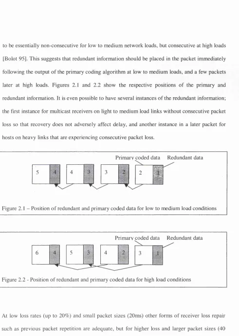
to be essentially non-consecutive for low to medium network loads, but consecutive at high loads [Bolot 95]. This suggests that redundant information should be placed in the packet immediately following the output of the primary coding algorithm at low to medium loads, and a few packets later at high loads. Figures 2.1 and 2.2 show the respective positions of the primary and redundant information. It is even possible to have several instances of the redundant information; the first instance for multicast receivers on light to medium load links without consecutive packet loss so that recovery does not adversely affect delay, and another instance in a later packet for hosts on heavy links that are experiencing consecutive packet loss.
Primarv coded data Redundant data
2
1
#
Figure 2 .1 - Position of redundant and primary coded data for low to medium load conditions
Primarv c ^ e d data Redundant data
Figure 2.2 - Position of redundant and primary coded data for high load conditions
At low loss rates (up to 20%) and small packet sizes (20ms) other forms of receiver loss repair such as previous packet repetition are adequate, but for higher loss and larger packet sizes (40
and 80ms) LPC redundancy is preferred to other receiver loss repair mechanisms.
2.5 Frequency Division Muitipie Access (FDMA)
With FDMA [Tanenbaum 96], the available bandwidth is divided into equal sized frequency
bands, each host being assigned one such frequency band for their own exclusive use. The allocation of hosts to channels is typically manually configured into the hosts. In effect, the broadcast medium has been transformed into a number of point-to-point channels, avoiding the problem o f contention between users. Although usually used with a centralised controller, a
distributed implementation is possible but more complex. For satelhte applications, the centralised controller is naturally the satellite, but satellites do not usually perform on-board processing, merely repeating information from the uplinks to the broadcast downlink.
Small frequency bands ("Guard bands") between channels are required to prevent interference. These guard bands can take up a substantial proportion of the available bandwidth. Hosts must also be carefully power controlled. Too much power in the main frequency band causes extra
power in the side bands, which causes interference with adjacent channels.
For a small, fixed number of users with a heavy (buffered) load of traffic (eg telephone carriers’
switching offices), FDMA is a simple and efficient allocation mechanism. Efficiency is likely to fall dramatically, however, in the following circumstances:
• The number of users is large (There is a higher probability of quiescent users.);
• The traffic presented is bursty (A typical ratio of peak to mean data traffic is 1000:1).
If less than the total number of hosts are transmitting all the time, bandwidth is wasted which could have been allocated to other active users. To overcome this limitation, dynamic allocation of channels can be used. An example of this is the "SPADE" protocol [Edelson 72], which uses a
common signalling channel to allow users to request a channel. Each (of up to 50) ground stations "owns" a slot in this channel and upon sensing that one of the 794 simplex data channel is currently idle, transmits a reservation request on its signaling channel. If, when the request is heard on the downlink, the data channel is still free, the request is assumed to have succeeded arid data transmission begins. After the transmission a deallocation message is transmitted on the signalling channel. If two or more hosts attempt to acquire a channel during the same signalling
period, a collision occurs and both hosts must retry later. (An alternative algorithm could have been that the host with the "lowest" frequency band wins, where lowest is redefined after every collision to allow fairness between hosts). Disadvantages with this reservation scheme are:
• manual préconfiguration of hosts to slots is needed in the signalling channel;
• the maximum number of hosts is limited;
• the delay (especially with geostationary satellites) inherent in the reservation process;
• the unfairness (one host could take all the channels, blocking other hosts).
Despite these problems, it is the expensive FDMA hardware that makes TDMA more commonly
2.6 Wave Division Muitipie Access (WDMA)
WDMA is an example of a distributed frequency division technique commonly used on fibre
optic, passive star LANs. Fibre can theoretically carry extremely high capacity but practically only a small percentage of this capacity can be utilised due to limitations in the speed of the
electrical to optical interface. WDMA exploits the fibre more efficiently by dividing the bandwidth into wavelength bands that are allocated to each host.
In this section a multiple access protocol proposed by Humblet et al. [Humblet 92] is described.
Each host is assigned a narrowband control channel (to receive only) and a wideband data channel (to transmit only). Both channels are divided into time slots, which are grouped into frames, and all stations are synchronised from a single, global clock. Frames are marked in a
special way, the last slot in the data channel being used to report the status of a host.
When a host wishes to initiate a communication, it tunes to the frequency of the data channel of the desired host and listens to the status channel. This gives information about free slots on the
control channel. It then selects a free control slot, and sends a "Data on my output slot 3" message. The receiving host tunes its receiver to the initiating host’s data channel frequency and
reads the contents of slot 3. [If two hosts try to send simultaneous messages a collision occurs.
The data in slot 3 is not picked up and the sender must notice the absence of an acknowledgement and resend a control channel message.]
request" message to a receivers control channel. The receiving host announces (on its status data channel) the assignment of the slot in the control channel to the requesting host. [If two hosts try
to send simultaneous requests a collision occurs and both try again a random amount of time
later.] Both parties now have a conflict free channel of communication. When there is data to transmit, the initiating host sends a "Data on my output slot 3" message (on the connected
control channel). The receiving host tunes its receiver to the initiating host’s data channel frequency and reads the contents of slot 3.
After a connection has been established, a message of the form "Data on every output slot 3" can be sent. If the receiver has no other commitment for slot 3, the request can be accepted. This
emulates a constant bit rate, connection-oriented service.
The concept that receivers tune to senders frequency can cause a problem when two senders instruct a single receiver to tune to their data channel for slot 3. The receiver has to choose one request at random and listen to only one of the two transmissions. Another problem is that every
transfer must be proceeded by a request, response communication which imposes addition transmission and propagation delay. It may be preferable for the sender to tune to the receiver’s
channel and inunediately send the data itself, if the frame is short.
Numerous other variations on this protocol are possible. All hosts can share a single control channel, for example. It is also possible to multiplex control and data channels together, allowing
2.7 Code Division Muitipie Access (CDMA)
CDMA takes frequency hopping wireless networks and allows different hosts to transmit
simultaneously, using different pseudo-random sequences known by all hosts. Coding theory separates transmissions, using the fact that multiple signals add linearly, allowing a single signal
to be extracted. Each bit is encoded into n chips (typically 64 or 128), and each host is allocated an n-bit "chip sequence". A 1 bit is transmitted as the chip sequence itself, a 0 bit is transmitted
as the complement of the chip sequence. For b bits the encoded version takes nb bits to transmit which makes CDMA a form of spread-spectrum communication. Although transmissions can begin at different points in time, correlation techniques enable the start point to be determined. The use of correlation to extract a signal can even be used to separate multiple overlapping
transmissions even when a single code is used.
CDMA is not easy to configure: chip sequences of all local hosts have to be allocated (manually)
to each host. Another disadvantage is the large radio spectrum that is required, if a reasonable bit rate is to be achieved. Power levels also have to be carefully controlled. Finally, despite increasing the length of the chip sequence, physical limitations (eg noise levels) can significantly
limit the capacity of CDMA systems.
2.8 Time Division Muitipie Access (TDMA)
TDMA [Tanenbaum 96] is based on the same principle as FDM A, except the available bandwidth is divided into a number of time slots, rather than frequency bands. TDMA requires
can synchronise. An additional complication is that the propagation time for the time signal to reach the hosts can vary (especially with geostationary satellites) not only because of varying
distances from satellite to hosts but also because satellites drift in orbit. The effect is corrected by
increasing the transmission speed to compensate for discrepancies, but this reduces usable bandwidth. A number of slots are aggregated into a "frame". The number of slots in a frame determines the maximum number of hosts, each host being allocated a slot number within each
frame.
As with FDMA, if a user does not use their allocated time slot, another user cannot use it. Like FDMA dynamic allocation of channels can solve this problem, and with TDMA this can be done in a centralised or distributed way. Advanced Communication Technology Satellite (ACTS)
[Palmer 90] uses a centralised mechanism, relying on one of the ground stations to be the MCS (Master Control Station) and manage time slot allocation. Each host is initially assigned one channel and has a dedicated control channel (which allows the system to be contention free). Request messages are sent to the MCS when another channel is required or a channel is to be
released.
A similar protocol that allocates a single control channel (bit) to each host, but does not initially allocate data channels is the bit-map protocol. The bit is set to indicate that the host has data to
transmit. The bit-map is a group of bits (one for each host) that precedes data frames. Since hosts with a position towards the end of the bit-map have a lower average channel access time than
hosts with a bit position at the beginning of the bit-map, alternative proposals BRAM (Broadcast Recognition Access Method) [Chlamtac 76] and MSA? (Mini Slotted Alternating Priorities)
[Scholl 76] suggest that as soon as a host has set its bit, it should transmit its data frame. After
transmission the bit-map recommences where it left off. The efficiency of these protocols is the
same as the bit-map method, but the delay characteristics, and fairness between hosts is improved especially at low loads.
The access delay for BRAM/MSAP can be further reduced at low loads, (but slightly lengthened at high loads) by using MLMA (Multi-Level Multi-Access) [Rothauser 77] that transmits a
host’s address in a coded form and relies on the uniqueness of addresses to differentiate transmissions. "Multi Level" refers to the number of levels needed to transmit an address, and varies with the radix used to represent the address. The technique relies on the principle that a transmitted "1" will overwrite a "0". Therefore, hosts listen during "0" bits, to detect any other
host transmitting a "1 " bit. The protocol can be arranged such that at the end of the contest, each host knows all other hosts with frames to transmit, so all pending frames can be transmitted in order without further contention.
The limiting case where the radix is 1 is known as the binary countdown protocol. If the frame format has the sender's address as the first field of the frame, then the contention bits are not
wasted. A problem arises because hosts with higher addresses have priority over lower addressed hosts. To solve this, the use of virtual host numbers has been suggested to allow host numbers to
cycle after a successful transmission. The channel efficiency is better than decimal MLMA when
2.9 ALOHA
Pure ALOHA [Abramson 70] is the simplest multiple access protocol, allowing a host to transmit a frame at any time without restriction. It is an example of a pure contention system;
meaning collisions between frames are possible. An acknowledgement from the receiving host allows the sender to determine whether or not the transmission was successful. If an
acknowledgement is not received within a timeout interval, the frame is resent after a random delay.
To calculate the maximum throughput for an ALOHA channel, the inter-arrival times of the start times of packets are assumed to be independent and exponentially distributed and the traffic
source is assumed to be a large enough population of users to be approximated by an infinite number of users who collectively form an independent Poisson source with an aggregate mean
packet generation rate of À packets/second. These simplifying assumptions are necessary to
facilitate analysis. The traffic itself is assumed to consist of fixed length packets taking T
seconds to transmit. The average number of packets generated per transmission time, S = XT. S
can also be thought of as the throughput or channel utilisation. The mean traffic offered to the
channel (consisting of new transmissions and retransmissions) is denoted by G and can be
thought of as the average number of packets per transmission time T, where G > S.
The channel throughput, S = G x Ps, where Ps = Probability of successful transmission. A packet is successfully transmitted if there are no other transmissions within time T before or after the
during 2T is Ps = e'^^. So, S = Ge'^^ and S reaches a maximum when dS/dO = 0 —> (l-2G)e‘^^ =
0 —> G = V"2 (ie when the offered load is half the channel capacity) at which point the maximum
throughput, S = l/2e = 18% (to nearest percentage.) Graph 2.1 shows throughput values over a range of offered load levels.
1
?
1
0-8
I
g 0.6E o. o •& 0.4
Z 3
^ o c/) ^ 0.2
Graph 2.1 : ALOHA Throughput Against Offered Load
0
0 0.2 0.4 0.6 0.8 1 1.2 1.4 1.6 1.8 2 2.2 2.4 2.6 2.8 3
G (N orm alised Load - b y tes)
2.10 Hybrid TDMA / Slotted ALOHA schemes
At low load, slotted ALOHA has similar channel efficiency to TDMA, but less access delay. At high load however, TDMA has much better efficiency than slotted ALOHA. Hybrid protocols have been developed which attempt to approximate slotted ALOHA's properties at low load (allowing more contention) and TDMA at high loads (limiting contention).
Reservation ALOHA [Crowther 73] allows more hosts than slots, by not allocating hosts a home slot. Instead hosts must compete for slots, but once a slot is won, the host may continue to use the same slot in future frames while it has data to send.
Unallocated reservation subslots can also be used [Roberts 73]. Hosts select a random subslot
and broadcast a short request frame. If the frame does not collide with another request, then the next regular slot is reserved. All hosts must monitor the subslots to determine how many data
slots to skip before transmitting.
A protocol to combine stream and bursty traffic was proposed [Binder 75] which allows other hosts to transmit in another host’s "home" slot if the slot goes idle. Other hosts can contend for the slot. Collisions cause all non-owner hosts to backoff for one slot, allowing the owner host to recover its slot for. future transmissions. Any unowned slots can be claimed by any host. The scheme still relies on there being at least as many slots as hosts.
The "Adaptive Tree Walk Protocol" [Capetanakis 79] starts by allowing all hosts to transmit. If a collision occurs, the number of hosts allowed to transmit is halved (based on bit-map position or address range). This is repeated until a single transmission is obtained. The protocol is called
"Tree Walk" because the hosts are logically arranged as nodes on a binary tree, and the tree is searched ("walked") until a level is reached where only one host below that level wants to
transmit. By continuing the traversal after a successful transmission, all ready hosts can be identified. The protocol is adaptive because under high load there is no point starting by allowing
all hosts to transmit; there will almost certainly be a collision. If each host keeps an estimate of the current network load, the appropriate starting level in the tree can be chosen to maximise the
The "Um" Protocol [Kleinrock 78] applies a probabilistic treatment to the size of the window of
hosts allowed to transmit. An analogy is made between the hosts and the balls in an um. balls are
either green (host has a frame to send) or red (host has no frame to send). The aim is to choose
the sample size such that only one green ball is selected, based on an estimate of the number of ready stations. If the estimate is that only one station wants to transmit, all hosts are allowed to transmit and the protocol is identical to slotted ALOHA. If the estimate of the number of hosts
that want to transmit is more than half the total number of stations, only one station is allowed to transmit and the protocol becomes TDMA.
Priority Oriented Demand Assignment (PODA) [Jacobs 79] is a protocol similar to Roberts’
except the boundary between data slots and reservation subslots can vary with demand. Also, future reservations can be made by setting certain bits in the data frame, including frame size and priority, and are either for a single frame or a stream of frames, (the intention being to
accomodate data and voice.) Scheduling takes reservation information into account when ordering transmissions, which improves efficiency compared to normal first come, first served scheduling used by the other algorithms. Contention PODA (CPODA) allows hosts to compete for subslots, as with Roberts’ protocol, and is used in SATNET, a satellite network between
America and Europe. Fixed PODA (FPODA) uses pre-allocated subslots, as ACTS does.
2.11 Carrier Sense Multiple Access (CSMA)
Shared networks are characterised by a single channel shared between multiple independent data
sources. One of the fundamental challenges of any shared network is the design of the multiple access protocol. That is, the design of the protocol that controls the approach each host has to
accessing the channel, and the method of rescheduhng the transmission after an unsuccessful
access attempt. The average and variation of the channel utilisation and access delay under
various network loads or numbers of transmitting hosts typically measure the success of the protocol. Multiple access protocols are often optimised for throughput under either low or high
load, as determined by the persistence of the protocol, and the characteristics of the backoff procedure. This is suitable for non-realtime traffic, but optimising for delay and loss are preferable requirements for most realtime applications.
Wireless local area networks have their own peculiarities that affect the multiple access protocol. Since the radio signal level has a wide dynamic range, and receiving is not possible while transmitting, collision detection is not an available option. Collision detection limits the damage
of a collision, improving the channel utilisation and access delay figures. Without it, collisions must be avoided by randomising the transmission time at moments of high collision probability to obtain acceptable performance figures.
Of all the multiple access techniques, CSMA [Halsall 95] is one of the simplest, and most widely
used protocols. If a host has a frame to transmit and carrier sense shows the medium is idle, the
host may transmit the frame immediately. If two stations transmit simultaneously, a collision occurs. If a frame is to be transmitted and the carrier is sensed to be busy, CSMA recognises that
when the carrier next goes idle there is a high probability of a collision, and so defers transmission at this time by a random number of “slot times” (a slot time is equal to the
Wait for frame to transmit. Format frame for transmission.
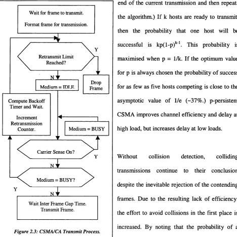
In P-persistent CSMA a frame is transmitted with probability p, if the carrier is idle. If the frame
is not transmitted, it defers until the next slot time and then, if the carrier is still idle, transmits
again with probability p. This continues until either the frame is transmitted or another transmission begins, in which case the host acts as if there has been a collision (waits until the
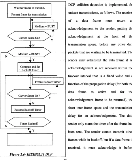
end of the current transmission and then repeats the algorithm.) If k hosts are ready to transmit, then the probability that one host will be
successful is kp(l-p)*^\ This probability is maximised when p = 1/k. If the optimum value for p is always chosen the probability o f success
for as few as five hosts competing is close to the asymptotic value of 1/e (-37% .) p-persistent CSMA improves channel efficiency and delay at high load, but increases delay at low loads.
Refransmit Limit Reached?
Medium = TDT.R
Compute Backoff Timer and Wait.
Increment Retransmission
Counter.
Drop Frame
Medium = BUSY
Carrier Sense On? N
Medium = BUSY? JS_
Wait Inter Frame Gap Time. Transmit Frame.
Figure 2.3: CSMA/CA Transmit Process.
Without collision detection, colliding
transmissions continue to their conclusion despite the inevitable rejection of the contending
frames. Due to the resulting lack of efficiency,
collision is highest immediately following a transmission, CSMA/CA (CSMA/Collision
Avoidance) defers transmission at this time by a random number of slots to lower the probability of a collision. The mechanism is equivalent to the behaviour of CSMA/CD (CSMA/Collision
Detection) after the first collision. If, after the backoff period, carrier sense indicates that another host chose a shorter backoff period, the host acts as if a collision has occurred: it waits for the
carrier to go idle, doubles its contention window and chooses another random backoff period. The exact behaviour is shown in figure 2.3.
Treating another transmission as a collision leads to the effect, also noted in CSMA/CD, known as the “channel capture effect” [Aimes 79] whereby a successfully transmitting host is able to
send subsequent frames uncontended. The currently transmitting host will reset its contention window to the minimum giving it a significant advantage over other competing hosts that are backing off their contention windows. The result with respect to channel efficiency is not detrimental as a host that ‘wins’ a round of contention can transmit for longer without having to waste bandwidth in other contests. The trade-off is an adverse effect on delay and delay variance,
which affects realtime applications.
The binary exponential backoff (BEB) algorithm is unfair because the longer a host has already been waiting, the longer it is likely to delay before attempting to transmit [Lazowska 79].
Alternative backoff algorithms that address this deficiency are described in the MACAW,
DFWMAC and BLAM sections.
When a “collision” occurs (the host senses the carrier busy), all active hosts wait a truncated
BEB time before retransmitting the frame. Each host chooses either the first or second slot time
in which to retransmit. This means that the probability of a further collision is 1/2 if two hosts are involved (and this probability increases as more hosts are involved.) On the tenth attempt, the
backoff algorithm waits for between 0 and 1023 slot times (the maximum). Even at this level, the
number of hosts waiting to transmit, and hence choosing an integer in this range, is crucial to the probabihty that a given host is successful in transmitting.
2.12 Token Passing
As opposed to CSMA, the token passing MAC method gives a bounded delay and is therefore deterministic. The token passing MAC method is independent of the physical topology. It can be apphed over bus and star, as well as ring networks.
2.12.1 Token Ring
Token Ring is defined in the IEEE802.5 standard [802.5 85]. It is characterised by a physical ring architecture into which all hosts are inserted, and a token passing access control mechanism.
Each station reads the frame by examining each incoming bit, and then repeating it. Thus there is a 1-bit delay added to the ring propagation delay by each host in the ring. Also, the "monitor"
host carries, on average, a 27-bit buffer, to ensure that the token can be completely contained on the ring. There can be up to 250 hosts on the ring. Each station is allowed to transmit frames up
to a token hold time (THT) of 10ms, by default. This figure hmits the maximum size of a Token
Ring frame to 4500 bytes for 4Mbps rings and 17800 bytes for 16Mbps rings. Also, an early
token release scheme was utilised, which allows a host to transmit the token directly after the final bit of the final frame, without having to wait for that frame to complete the ring.
With any kind of physical ring, the medium is still shared (like Ethernet) but, because each host
connects into the ring, there are no collisions. At 16Mbps, each bit takes 0.0625ps to transmit. With 250 hosts in the ring, a 250-bit delay is added (15.625ps). The 27-bit buffer in the monitor
station adds an extra 1.6875ps delay.
Priority operation is possible using frame control bits within each frame that indicate the current
priority. Each host is able to request that the priority of the ring be raised if it has a high priority frame to transmit. Eight levels of priority are possible.
The insertion/removal of hosts into the ring causes disruption to the ring and hence more management effort to restore order. A frame in transit during a host insertion/removal will
almost certainly be corrupted.
With a THT of 10ms, if 250 hosts in a ring decide to hold the token for the maximum time, the worst-case access delay is 2.5s. This is clearly unacceptable for many real-time applications.
Even with a priority system, the worst-case scenario is still the same (250 stations all with high priority frames to transmit). To reduce this figure, the maximum number of hosts on the ring can
be reduced, the maximum frame length can be reduced, or the speed of the ring can be increased. Decreasing the size of the maximum frame length reduces utilisation (due to extra header
overhead), but this may be the price that has to be paid for the faster access times demanded by
2.12.2 Token Bus
This standard is defined by EEEE802.4 [802.4 85]. A bus architecture is logically configured as a
ring, allowing a token passing access control method to be used. The operation of the token bus
is very similar to the token ring, except that ring management is more complex due to
maintaining the logical nature of the ring. In particular, adding and removing hosts is more complex and the initialisation and lost token recovery algorithms vary considerably.
In order for a host to join the logical ring, each host occasionally opens up a "response window"
(equal to the IEEE802.3 slot time), when traffic load is low, allowing other hosts to join. It sends a "Solicit Successor" frame that contains its own address and the successor’s address. Any host with an address within this range can bid to enter the ring. If exactly one host bids, the host is entered into the ring and the token holder passes the token to the newly entered host. If more
than one host transmits, the transmissions collide and the token holder must send a "Resolve Contention" frame. The contending hosts resolve the contention using a combination of the binary countdown protocol (two bits at a time) and collision avoidance (two random bits are used
to delay each transmission by 0, 1, 2 or 3 slots). Only one host can enter the ring, per solicitation, to set a bound on the amount of time spent in ring maintenance. Under constant high load the time taken for a host to join the ring is not bounded, however.
When a host wishes to leave the logical ring, it waits until it holds the token, then sends a "Set Successor" frame to its predecessor, with its successors address. It then passes the token to its
successor and drops out. A host could chose to leave by just not responding to the token but the
other hosts in the ring have to detect and repair the ring.
When a host transmits the token to a host that has gone down, it waits to hear if its successor
transmits either a frame or the token. If no transmission is heard, the token is transmitted a second time. If this also fails, the host transmits a "Who Follows" frame that includes its
successor’s address. A station recognising this address as its predecessor responds with a "Set Successor" frame indicating itself as the new successor. The token holding host then transmits the token to this new successor and the logical ring is healed. If there is no answer to the "Who
Follows" frame, the host sends a "Solicit Successor" frame and follows the same procedure as opening a response window to allow hosts to enter the ring.
If a host holding the token fails, the first host to time-out will transmit a "Claim Token" frame, and the modified binary countdown algorithm with random start time is used to resolve
contention. If there are multiple tokens in the network, a host that notices another transmission whilst holding a token will drop the token. This will continue until there is only one token.
Initiahsation is a combination of the "Claim Token" procedure (when a host fails while holding
the token), followed by the "response window" algorithm to allow more hosts to join the ring.
Token bus uses the timed token rotation protocol to control ring access time. Each host keeps a record of the time that has elapsed since it last had the token. If the time is less than a target
token rotation time (TTRT) then the host is allowed to transmit up to this time. It can be shown
that each host on the ring receives an equal amount of bandwidth, and hence the algorithm is fair. Unfortunately, under increasing load, a lot of hosts, upon receiving the token, cannot transmit
waiting frames as the TTRT has expired. This leads to a lot of token passing overhead, and hence
low utilisation and higher access delays. With any token passing scheme, the token passing
overhead has to be kept low to make the method effective at low loads.
A priority mechanism is used in conjunction with the timed token rotation protocol. Each host is
allowed to transmit high priority frames when it first receives the token, up to a High-Priority Token Hold Time (HP-THT). The amount of time taken to transmit high priority frames is subtracted from the Token Hold Time (THT), to determine the time remaining for lower priority frames to be transmitted. The method of transmission of high priority frames is similar to the basic token ring method and so suffers less from token overhead. The amount of time that high
priority frames can be transmitted, however, is a preset default, the value of which affects access delay.
2.12.3 RETHER
The Token Bus standard covers the physical and the link layer, although the token passing MAC should be independent of the underlying physical architecture. RETHER (Real-Time Ethernet)
[Venkatramani 95] demonstrates how a token passing layer can be added to standard Ethernet to offer more services to real-time applications. The network operates in CSMA/CD mode until a
real-time request is received, at which point a broadcast control frame alerts all hosts to switch to token passing. In token passing mode real-time traffic is given access first, non-real-time traffic
uses the token for the remaining time in a cycle. When the final real-time stream terminates,
CSMA/CD mode is resumed with another broadcast message. If two hosts try to initiate a switch, the one with the lowest address wins. The successful host must receive acknowledgements from
all other hosts before transmitting the token.
Real-time data is assumed to be periodic and the period must be an integral number of Token
Rotation Times (TRTs), which is a system configurable variable. Each real-time node may hold the token for up to its pre-established Token Holding Time (THT). Each non-real-time node may
send at most one frame. It is also possible for the token to pass round multiple streams within one host. The token holds the residual time left in each cycle, a list of currently active real-time sessions with their bandwidth reservations and a list of "dead" nodes in the subnet.
When the host holds the token it reads the current reservation information and determines whether to admit a new real-time session. Nonrreal-time traffic must be allocated a minimum amount in each cycle, to stop starvation. If the session can be admitted the information is added to the token and the data can be transmitted in the next cycle. Reservations can also be removed
when the host holds the token. Due to the state being kept in the token and the requirement that the token must be held whilst a reservation is being made or removed, race conditions are avoided.
For robustness, each host must send an acknowledgement to its predecessor in the logical ring
piggybacked onto the token sent to its successor. If an acknowledgement is not received, the node updates the list of dead nodes, and the list of reservations, and passes the token to the next
2.12.4 Fibre Distributed D ata Interface (FDD!)
The FDDI standard is formally defined in IS09314 [ANSI 87]. Physically, the architecture is an optical fibre ring that can be up to 100km in circumference with up to 500 hosts on the ring.
Operating at a speed of 100Mbps, it is often chosen for use as a MAN, but can also be used in high performance LAN environments. Due to the encoding used (4B5B with NRZI) two symbols
have to be read before a byte can be decoded. Thus, there is a two-symbol delay at each host. At 100Mbps this delay is O.OSjis. The total delay at each station is rounded up to Ips, in the standard, when internal gate operations are also taken into account.
The propagation delay for a maximum size ring o f 100km at 195m/|is (the speed o f light in glass) is 0.5ms. When a per host delay o f Ips with 500 hosts on the ring is added the total delay is 1ms.
The maximum frame size for FDDI is given as 4500 bytes. The transmission time for such a maximum length frame is 360ps. The worst-case access delay is when every host has a frame to transmit. With 500 hosts, this is 180ms. Limiting the maximum frame size and number of hosts significantly reduces this figure.
FDDI uses the same timed token rotation protocol that Token Bus uses. The problems with excessive token passing overhead are more apparent on a large ring, where the propagation delay
is larger. A priority mechanism (similar to Token Bus) is also available.
2.13 Multiple Access Collision Avoidance (MACA)
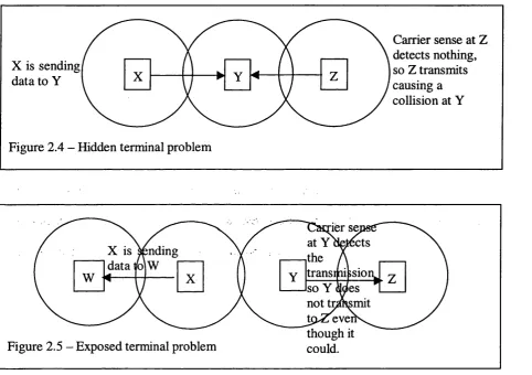
CSMA suffers from the “hidden terminal problem” - where carrier sense is unable to detect that
a transmission is taking place because the transmitter is out of range, see figure 2.4 - and the
“exposed terminal problem” - where carrier sense stops a transmission which could take place without collision, see figure 2.5.
X is sending! data to Y
Figure 2.4 - Hidden terminal problem
X 1 1 I / k^ Y ^ 1 1I I Z
Carrier sense at Z detects nothing, so Z transmits causing a collision at Y
Figure 2.5 - Exposed terminal problem
ler se at Y detects the
X IS ending data K)\w trans JSIO so Y not tpAsmit tpxZevei though it could.
MAC A [Karn 90] attempts to solve these problems by transmitting a short "Request To Send" (RTS) frame preceding the actual data transmission. The receiver is required to send a "Clear To Send" (CTS) in response. Data transmission can then begin. The RTS/CTS exchange is known as
“virtual carrier sense” as opposed to “physical carrier sense.” Physical carrier sense is not used as
it creates the exposed terminal problem - hence the name MACA (CSMA/CA without the CS).
The effect of the RTS/CTS exchange is that the CTS alerts hosts close to the receiver, but
potentially out of reach of the sender, that a transmission is about to take place. The CTS
includes the upcoming frame length (obtained from within the RTS message), so that the hosts in
the vicinity o f the receiver will know the duration for which to keep quiet, even though they will not be able to sense the actual transmission.
RTS control frames can still collide, however, and so, in the absence of CSMA, hosts use a randomised exponential backoff procedure before transmitting an RTS. If no CTS is heard within
a certain time, the time is doubled before an RTS is retransmitted. This is repeated up to a retransmission limit at which point the sending host gives up. Other hosts hearing an RTS or CTS also add an extra random interval to the time they are prevented from transmitting in order to reduce the probability of collision at this time, as CSMA/CA does. MACA also states that if
the data frame is as short as an RTS, then a host can decide not to use the RTS/CTS handshake as this creates unnecessary overhead in this case.
Finally, MACA describes the use of an automatic power control mechanism that adds the power level recorded when the RTS arrived in the following CTS frame. The data packet can then be sent with just enough power to reach the receiver. This allows more spatial reuse of the radio
channel. Hosts that overhear a CTS frame, and know the power level necessary to reach the host
that transmitted the CTS frame, may be able to transmit an RTS to another host with temporarily lower power without interrupting the forthcoming data transfer. The power level required to send
a CTS may be learnt by experience (start with low power and keep increasing every time a