Position Control of Servo Motor Using
Fuzzy Logic Controller
Nirmala Ashok Dange1, Ashwini Pawar2
Student, Department of Electrical Engineering, G.H.Raisoni Institute of Engineering And Technology, Pune, Savitribai Phule Pune University, Pune , India1
Prof., Department of Electrical Engineering, G.H.Raisoni Institute of Engineering And Technology, Pune, Savitribai Phule Pune University, Pune , India2
ABSTRACT: The vast majority of the modern procedures utilize the ordinary PID controllers because of their straightforward and vigorous outline, reasonable cost, and viability for direct frameworks, however routine PID controllers are generally not powerful if the procedures included are higher request and time delay frameworks. For this, Fuzzy Logic controllers were showed up. On the off chance that we consolidate the two shrewd control frameworks, the issue will be determined. The use of FLC's to servo frameworks produces results better than traditional controllers. It is seen that, if there is an adjustment in framework parameters or burden unsettling influences, the reaction of framework because of corresponding necessary subsidiary (PID) controller is significantly influenced and PID controller needs retuning . Be that as it may, FLCs protect the wanted reaction over extensive variety of framework parameters and burden unsettling influences. A FLC more often than not gives preferable results over those of traditional controllers, as far as the reaction time, settling time and especially in strength. The goal of this paper is to analyze the time determination execution between routine controller and Fuzzy rationale controller in position control arrangement of a DC servomotor. This will incorporate configuration and improvement of a controller for position control utilizing Matlab/Simulink. The extent of this work is to apply two sorts of controller in particular PID and Fuzzy rationale controller. The product part incorporates programming ongoing programming utilizing Matlab/Simulink. At long last, the product will be incorporating with equipment for position control of servo framework.
KEYWORDS:PID, fuzzy logic, position control system, servomotor.
I. INTRODUCTION
subjectively, estimated or with instability. The utilization of FLC fundamentally changes the way to deal with control of drives. A customary controller changes the framework control parameters on the premise of an arrangement of the differential mathematical statements, which depicts the model of drive framework. In a Fuzzy controller, the changes are made by a Fuzzy standard based master framework, which is a consistent model of human conduct of the plant administrator [7], [8]. A FLC generally gives preferable results over those of ordinary controllers, regarding the reaction time, settling time and especially in heartiness. The strength of FLC is estimable component in engine drive applications, where, the framework parameters are broadly changing amid plant operation. Because of non-straight structure of the FLC, the primary outline issue lies in the determination of the steady and finish guideline set and the state of enrollment capacities. Nonetheless, FLC's outline is made less demanding by cordial and importance apparatuses of the Fuzzy rationale. In this paper, the idea of Fuzzy rationale has been utilized for position control, utilizing dc servomotor. Subsequent to the presentation of Fuzzy set hypothesis by Zadeh and the primary innovation of a Fuzzy controller by Mamadani, Fuzzy control has picked up a wide acknowledgment, because of the closeness of surmising rationale to human thinking and has discovered applications in numerous force plants and power frameworks. It gives a powerful method for changing over the master sort control information into a programmed control methodology. Two reasons regularly marked for seeking after Fuzzy control are the longing to fuse semantic control rules and the need to outline a controller without adding to an exact framework model. The main Advantages of the fuzzy control systems are as follows-
1. It is not necessary to build a detailed mathematical model 2. Fuzzy controllers have a high strength and a high adjustment. 3. They can operate with a high input numbers.
4. They can be adapted easily into nonlinear systems 5. The human knowledge can be easily applied 6. The process development time is relatively lower
II. NONLINEARITIES INVOLVED IN PLANT
The exhibitions of the servo framework specifically influence the strength, reaction speed and following precision of the machine device. In a servo arrangement of CNC machine device, it confronts a vital issue that it ought to still keep great element attributes and unfaltering state following precision with the impacts of time variety, nonlinearity and burden unsettling influence. Conventional PID controller is generally connected in the servo framework, yet it can't address the issues of parameters conforming capacity and unsettling influence dismissal ability. Fuzzy control is a wise control strategy which impersonates consistent considering human and is free on a precise scientific model of the controlled article. Besides, it is inhumane to parameters Variation, and has solid vigor. It is splendidly connected to beat the impacts of nonlinearity, time variety and coupling of servo framework. To the issue that the consistent state blunder is difficult to be disposed of with a Fuzzy controller, a Fuzzy PID controller is proposed in this paper. The proposed controller fuses in excellences of both control methodologies, which are adaptability, flawless unsettling influence dismissal ability of the Fuzzy control, and the high consistent state accuracy of PID control.
III. DESIGN OF CONTROLLER
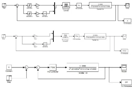
Figure 1: Block Diagram of Fuzzy, PI and PID Controller
1. Ziegler-Nichols Method
Ziegler and Nichols had proposed a famous tuning parameter of PID controller in 1942. Steps involved in this method are as follows:
1. First, note whether the required proportional control gain is positive or negative. To do so increase the step the input under manual control and see that the resulting steady state value of the process output has also increased. If so, then the steady-state process gain is positive and the required Proportional control gain, KP,
has to be positive as well.
2. Turn the controller to P-only mode, i.e. turn both the Integral and Derivative modes off.
3. Turn the controller gain, KP, up slowly (more positive if KP was decided to be so in step 1, otherwise more
negative if KP was found to be negative in step (1) and observe the output response. When a value of KP
results in a sustained periodic oscillation in the output, mark this critical value of KP as Ku, the ultimate gain.
Figure 2: Response of Ultimate Gain
With some real processes the response to a step change or set point disturbance differs depending on the direction or size of the change. In this case it is irrelevant to look at the open-loop response to tune the controller. Instead the closed-loop response i.e. the behavior of the system with control has to be studied. The values of KP, KI and KD are
calculated from table 1.
IV. DESIGN OF FUZZY LOGIC CONTROLLER
The Fuzzy Logic Controller is intended to have two Fuzzy state Variables and one control variable for accomplishing position control of the DC Servo Motor. These two info variable are the blunder and change in mistake. It demonstrates the fundamental piece chart of Fuzzyrationale controller with data and yield variables. of a controlled framework is depicted by an arrangement of Fuzzy acquainted memory (FAM) decides that associate a Fuzzy information set to a Fuzzy yield set of the FLC. These principles are given by Mamdani consequently it is called as Mamdani's FIS.
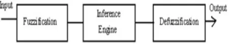
Figure 2: Block Diagram of Fuzzy Inference System
Crisp input information from the sensor is converted into fuzzy values for each input fuzzy set with the fuzzification block. The decision making logic determines how the fuzzy logic operations are performed and together with the knowledge base determines the outputs of each fuzzy IF-THEN rules. These two components are combined into the inference block. All the outputs are combined and converted to crispy values within the defuzzification block. Fuzzy rules can be described as a relational matrix R,R=E x EC KP x Ki x Kd
The error signal is the difference between the set point and output position of the motor. Following seven linguistic terms are used for the fuzzy sets i.e. negative big, negative medium, negative small, zero, positive small, positive medium, positive big which are denoted NB, NM, NS, ZE, PS, PM, PB respectively. The fuzzy sets are then defined by the triangular membership functions.
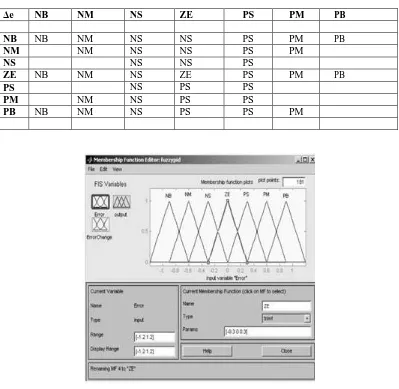
TABLE 1RULE BASE FOR FIS
Δe NB NM NS ZE PS PM PB
NB NB NM NS NS PS PM PB
NM NM NS NS PS PM
NS NS NS PS
ZE NB NM NS ZE PS PM PB
PS NS PS PS
PM NM NS PS PS
PB NB NM NS PS PS PM
Figure 3: Membership Functions for Error and Change in Error
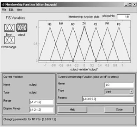
1. Output of FIS
Figure 4: Membership Functions for Output of FIS
V. OVERVIEW OF SERVO SYSTEM
The review of servo system where set point is given through personal computer. The computer program (FIS) output is given to DAC which converts digital to analog signal. This analog signal is given to driver circuit of servo amplifier. From driver circuit output is given to servo amplifier which amplifies current to the motor. A potentiometer is connected to the shaft of the motor and a voltage of 5V is given to it, which is distributed over 360°. Thus the motor shaft position is converted in voltage signal and given back to PC through ADC as feedback signal.
From set point and feedback signal error is calculated the difference between the errors of two conjugative iterations gives change in error and this error and change in error is given as input to FIS which gives the output signal to achieve desired position.
TABLE 2 SYSTEM PARAMETERS
Potentiometer sensitivity (Kp) 5.093 V/rad Signal amplifier gain (Ka) 1
Back EMF constant (K) 15x10-3 V/rad/s Armature Resistance (R) 2
Armature Inductance (Lr) 1mH
Motor Torque Constant (K ) 15x10-3 N-m/A r
Combined moment of inertia motor 42.6x10⁻⁶ Kg-m2 shaft & load referred to the
motor shaft side (Jm)
Figure 5: Block Diagram of Servo System
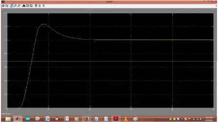
VI. SIMULATION RESULTS
Figure 6: Output Response with Fuzzy, Fuzzy PI and Fuzzy PID Controller
TABLE 3. TIME RESPONSE PARAMETER
CONTROLLER TYPE
TR (SEC) MP (%) TS (SEC) (ESS) (%)
PID Controller 0,018 9,23 0,07 4 FLC 0,07 0 0,12 0
VII. CONCLUSION
It is seen that the fuzzy controller preserves the desired response, even in the presence of load disturbance and varying contra1 environments. This ensures the controller’s robustness. The choice of rules and membership functions has considerable effect on fuzzy
Controller performance, e.g., rise time, settling time, overshoots etc. It is observed that using the superposition of different consequent active at particular region of domain, for the same combinations of antecedents, performance of FLC is improved considerably in terms of settling time and overshoot. The combination of two sets of rules with same antecedents but different consequent reduces the settling time and overshoot.
REFERENCES
[1] I. J. Nagrath and M.Gopal, “Control System Engineering.” Fifth Edition.
[2] Xiaodiao Huang and Liting Shi, “Simulation on a Fuzzy-PID Position Controller of the CNC Servo System”, Sixth IEEEInternational
Conference on Intelligent Systems Design and Applications (ISDA’06), 2006.
[3] Dongmei Yu, QingdingGuo and Qing Hu, “Position Control of Linear Servo System Using Intelligent Feedback Controller”, Sixth IEEE
International Conference on Intelligent Systems Design and Applications (ISDA’06), 2006.
[4] A. B. Patil, A.V.Salunkhe, “Temperature Controller Using Takagi-Sugeno Model Fuzzy Logic” Asian Conference on Intelligent Systems and Networks, 2006.
[5] MohdFua’adRahamat& Mariam md Ghazaly, “Performance Comparison between PID And Fuzzy Logic Controller in position Control System of DC Servomotor. Journal TeknologiMalayshia,45(D), 2006.
[6] K. S. Tang, Kim Fung Man,Guanrong Chen, and Sam Kwong, “An Optimal Fuzzy PID Controller” IEEE Transactions onIndustrial Electronics,48(4), 2001.
[7] Maki K. Habib, “Designing of Fuzzy Logic Controllers for DC Servomotor Supported by Fuzzy Logic Control Development Environment” IECON01:The 27th Annual Conference of the IEEE Industrial Electronics Society. 2001.
[8] C. C. Lee, “Fuzzy Logic in Control Systems: Fuzzy Logic Controller, Part II” IEEE Transactions on Systems, Man. andCybernetics,20(2), 2000.
[9] George K. I. Mann, Bao-Gang Hu, Raymond G. “Analysis of Direct Action Fuzzy PID Controller Structures, IEEETransactions on Systems,