ISSN: 2319-8753
I
nternational
J
ournal of
I
nnovative
R
esearch in
S
cience,
E
ngineering and
T
echnology
(An ISO 3297: 2007 Certified Organization)
Vol. 3, Issue 3, March 2014
Development of the CAD system for designing
non-standard constructions from elastomers
Vladimir Lavrik
1,
José Italo Cortez
2,
Vitaliy Mezhuyev
1, Liliana Cortez
2, Anna Alekseeva
1, Gregorio T.
García
2, Pedro G. Juarez
2, Javier Poblano
2Depart ment of Informatics and Software Engineering Berdyansk State Pedagogical University Berdyansk, Ukra ine1 Research Laboratory of Digital Systems and Renewable Energy Bene mérita Un iversidad Autónoma de Puebla,
Mexico 2
Abstrac t: The develop ment of the Co mputer-Aided Design (CAD) system FORTU-FEM , which is based on the Finite-Ele ment Method (FEM), is considered in the paper.Unlike other CAD systems, which does not allow to its users to change the schema of calcu lation, FORTU-FEM has the open architecture and allo ws to engin eers to develop the various methods for analysis of non-standard constructions. The exa mple of application of FORTU-FEM for calculation of the tensional and the deformed states of constructions from e lastomers is given.
Ke ywor ds: finite-e le ment method; FORTU- FEM, CAD
I. IN TRO DUC TION
The modern CAD systems for exploring properties of materials in the tensional and the deformed
conditions, support a number of mathematical methods for approximate calculations (e.g. solving
the big systems of algebraic and transcendental equations, the numerical integration and
differentiation etc.), but not often give the possibility of realization of non-standard calculations[1,
2]. The common iterative and the step-by-step computation schemes, which are based on the
multiple repetition of operations, for the realization of the different non-standard calculations
should be taken.
At implementation of the non-standard computations, including solution of the tasks of mechanics
of elastomers, the problem of the development of the most effective, if possible, the optimal,
calculation scheme arose [7]. Such the scheme on a number of methods of calculus mathematics is
based. The possible solution here is to build the different computing algorithms, and then to
compare their advantages and shortcomings. Next, at its program implementation, the problems of
saving computer memory and of improving performance of calculations to be solved.
Let’s note, that in the current stage of material science development it is rather difficult to say
beforehand about the optimality of a computing scheme in the concrete conditions. More often a
CAD system includes the different computational algorithms, and their advantages and weaknesses
are compared by users experimentally. For it, both the final and t he intermediate results of
calculations have to be investigated on their correspondence to the mechanical sense of the task.
This is quite important part of the method, since the errors of rounding and the instability of some
calculation algorithms can considerably change the results. The process of the analysis of results is
very difficult and labor- intensive, taking sometimes more time, than the whole procedure of
calculation.
ISSN: 2319-8753
I
nternational
J
ournal of
I
nnovative
R
esearch in
S
cience,
E
ngineering and
T
echnology
(An ISO 3297: 2007 Certified Organization)
Vol. 3, Issue 3, March 2014
the calculation scheme, represents initial and final conditions, selects the software methods,
analyses the results of solution, etc. For this reasons the CADs, intended for solving non-standard
problems should be developed correspondingly to some principles. In this paper we propose the
new approach to development of the CAD for designing the non-standard constructions from
elastomers, being in the tensional and the deformed conditions.
II. DEV ELO PMENT O F THE CAD SYSTEM FO R DESIGNING NON-STANDARD CONSTRUC TIONS FROM ELASTO MERS
The solution of non-standard tasks needs development of the CAD system having the open architecture, i.e. a llo wing to users to define own methods. We can allocate the next directions of such the systems development [3]:
development of the CA D systems for generation of applied progra ms on the base of the composition of the e xisting modules, stored in the relevant libra ries (software repositories). The computation scheme is offered to users in the form of various scenarios (stereotypic procedures) as the sequence of operations of the automated design together with the e le ments of inc luded in the CAD a tra ining system [5]. This approa ch is used quite often now, because it is less labor-consuming in rea lization o f solutions of non -standard problems. However, it has one essential issue: impossibility of develop ment of a new ca lculation method if the CAD libra ries do not contain the corre sponding scenario;
development of the high level proble m-oriented programming languages inside a CAD system. Such the approach is a very perspective today, however it requires the considerable resources for development of such the languages, their toolset (interpreters, translators, debuggers etc.), as also teaching users to those languages. And there is a problem o f train ing engineers to use of such the CAD systems, which are much more co mp le x co mparat ively with traditional ones;
the direct use of the models of the subject domains as the source languages for development of progra ms for the solution of the applied tasks. This approach is the most user friendly, however, the development of such the meta -programming CAD systems is also labor-intensive process.
In the first mentioned direction the nu mber of the CA D systems for automation of the process of the analysis of problems of mechanics of the deformed firm bodies is developed today. Among the most popular lets note the СОSАR, COSMOS/M [11]:, M ONOMAH, SCA D Office (plugin for AutoCAD) [6]:, LIRA [4]:, PROCHNOST -1, etc. [1] All the mentioned CAD co mple xes on the solution of the different classes of problems of mechanics of the deformed firm bodies are focused. The convenience of work and the high precision of calcu lations are their advantages. However, it should be noted, that the effective application of these CAD systems requires the considerable e xpenditures for the preparation of its users. Besides, these programs are also very expensive. But the ma in issue that the mentioned CAD systems can't be applied to the solution of the tasks, which methods are not provided by the system.
From our point of view, for increasing reliability and efficiency of the CAD systems, the synt hesis
of the two last directions is the most interesting, because a user knows the language of own subject
domain and so can master the corresponding problem-oriented programming language rather
quickly. In the same time, the probability of emergence of programs errors in the case of
application of such the approach also is less.
ISSN: 2319-8753
I
nternational
J
ournal of
I
nnovative
R
esearch in
S
cience,
E
ngineering and
T
echnology
(An ISO 3297: 2007 Certified Organization)
Vol. 3, Issue 3, March 2014
The design principles of FORTU-FEM are diffe r fro m the e xisting CA D systems. The idea here is that by the given set of init ial data and by the large-block scheme of the solution in the interactive mode a user can realize own process of the numerical solution and the analysis. So FORTU -FEM supports user at all stages, starting fro m the setting the init ial informat ion, develop ment of o wn methods of calculat ion and finishing the analyses of the numerica l results of solution of the intension and deformation states of a body.
The FORTU-FEM co mbines the several directions in develop ment of the proble m-oriented CA D tools: the specialized source language allows to the user-nonprogrammer to forma lize the description of the specific task of mathe matical physics and also to imp le ment the method of calculation correspondingly the computing scheme. As the mathematical base of the offered method for description and solutions of the problems of mechanics the variations calculus is taken, allo wing to describe in the most general forma l form the energetic variat ion princ iple and the method of its minimizat ion. Using this approach for description of tasks allows completely abs tract from the type and the method of solution at the initial stage. For development of the computing scheme it is necessary only to describe the rules of inferring the ma in re lations of the variation functional and to choose the method to find its min imu m .
The FEM system is open and this allows us to expand its functionality. Our impact in imp roving of FORTU-FEM is the development of the module for ca lculat ion of the constructions being in the tensional the deformed states, on the base of the method of mo ment diagra ms [2]. Let’s consider the e xa mple which shows the advantages of using our module for mode lling elastome rs.
III.CO NTAC T INTERAC TION O F A COMPRESSION RING AND A DISCRETE BASE
In the design of electrical transformers the proble m o f contact interaction of co mpression rings and a discrete base – pole-mounted pilla rs arises (Fig. 2). One of the objectives of a design of electrical transforme r is defin ition of the optima l p lace ment of brackets – co mpression ring seals. Th rough them the load P is g iven to the rings
.
The problem is that with the wrong choice of points of the load application the contact forces are unevenly distributed on discrete base, which significantly deteriorates the strength characteristics of the transformer.We solve this task with the help of FORTU-FEM system. The ring and the base are made of orthotropic materia l – corrugated cardboard. The FEM model obtained with the help of A NSYS system [10] and consist of 9920 nodes and 29484 FE in the form of a tetrahedron (Fig. 3).
P P Z Y X Pre-processor CAD FORTU-FEM
Processor Post-processor
Database m odel constructions Database FORTU-3 of the program s Database of m atrices (MFE) Base of projected constructio ns
ISSN: 2319-8753
I
nternational
J
ournal of
I
nnovative
R
esearch in
S
cience,
E
ngineering and
T
echnology
(An ISO 3297: 2007 Certified Organization)
Vol. 3, Issue 3, March 2014
Figure 2. Contact interaction of a compression ring and a discrete base
Figure 3. A discrete model of the ring and the base
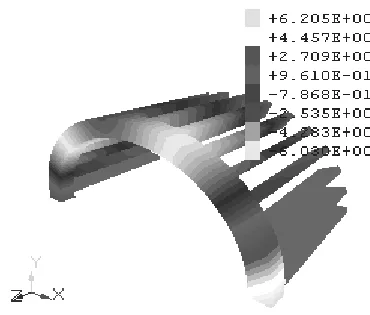
Fig. 4 shows the distribution of vertical displace ments w along the compression ring and the discrete base. Light grey on the compression ring area shows its backlog fro m the bottom (t wo bottom base pilla rs are not involved in the contact). Fig. 5 is a graph of the distribution of contact forces on the pillars, and Fig. 6 – the impact of contact force on the shape of the ring. It is clearly seen that with this type of loading, the part of the ring is behind the pillars (there are no contact forces on two pilla rs).
ISSN: 2319-8753
I
nternational
J
ournal of
I
nnovative
R
esearch in
S
cience,
E
ngineering and
T
echnology
(An ISO 3297: 2007 Certified Organization)
Vol. 3, Issue 3, March 2014
Figure 6. The distribution of contact forces on the ring
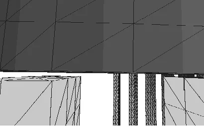
Fig. 7 is an enlarged vie w, showing a gap between the ring and pilla rs.
The comparison of the results obtained in systems FORTU -FEM and ANSYS, showed their good correlat ion.
IV.CO NTAC T INTERAC TION O F THE SHELL AND CRADLE
When transporting or storing in a horizontal pos ition shell structures are set on circular colu mns – cradles (Fig. 8.). Interaction of reinforced shell structures and cradles through pillar’s fra mes whose length along the axis of the shell is comparable with the width of cradles, but less than the radiu s of the shell and the size of the contact area.
ISSN: 2319-8753
I
nternational
J
ournal of
I
nnovative
R
esearch in
S
cience,
E
ngineering and
T
echnology
(An ISO 3297: 2007 Certified Organization)
Vol. 3, Issue 3, March 2014
Figure. 8. The distribution of stresses in the inclusion zone
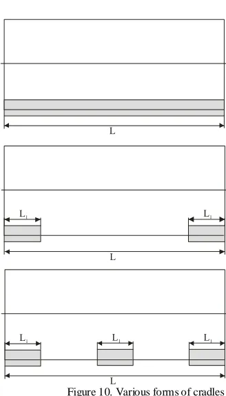
This task was solved with the help of FORTU-FEM system in three-dimensional setting for the three cases: in one, t wo and three cradles according to the length of the shell (Fig. 9).
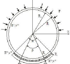
The distribution of contact forces depends on the hardness of the cradle, place of application of concentrated reactions (the angle of plac ing the pillar o f the cradle β ) and the cradle’s angle of contact α.
In case of equal radii of curvature of contact surfaces, the shell structure and the cradle along the a xis of the shell and a t a constant length along the axis of the shell cradle, the an gle of contact defines the boundary of the contact area. The value of the contact area can only decrease due to the lag of the support bulkhead fro m the c radle [10]. The solution to this task lies in the selection of design parameters that min imize the area of the shell gap fro m the cradle.
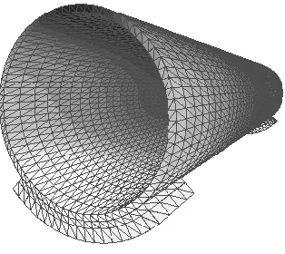
Fig. 10 shows the finite ele ment model of the shell and the different cradles. A discrete model of the shell consists of 5904 nodes and 17280 FE (finite e le ments) in the form of a tetrahedron. Overa ll d imension of the proble m for the shell and a cradle is 7462 nodes and 21,600 FE.
ISSN: 2319-8753
I
nternational
J
ournal of
I
nnovative
R
esearch in
S
cience,
E
ngineering and
T
echnology
(An ISO 3297: 2007 Certified Organization)
Vol. 3, Issue 3, March 2014
L
L
L1 L1
L
L1 L1 L1
Figure 10. Various forms of cradles
The task was solved with the fo llowing geometric para meters:
R
R
c
1
.
5
m,R
1
1
.
6
m,R
2
1
.
4
m,L
10
m,1
1
L
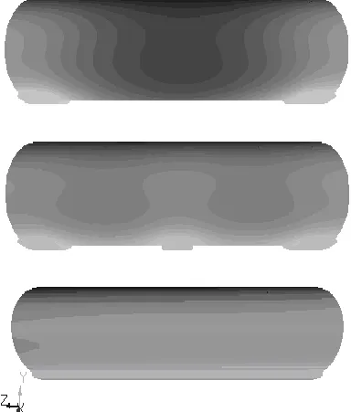
m.Fig. 13 shows the distribution of the vertical co mponent of displacement v along the shell and the cradles.
ISSN: 2319-8753
I
nternational
J
ournal of
I
nnovative
R
esearch in
S
cience,
E
ngineering and
T
echnology
(An ISO 3297: 2007 Certified Organization)
Vol. 3, Issue 3, March 2014
Figure 12. A discrete model of cradles
In the case of a single cradle the solution obtained with the help of FORTU-FEM qualitatively co incides with the known solution for the planar case, described in [8, 9].
Figure 13. The distribution of displacements v
It was also shown that in 2
3 1 2
3 2
1 10
) (
)
(
R R E
R R
E the contact efforts will be focused only on the edges of the contact are a.
To change the nature of the contact between the skin and the cradles a soft elastic layer is introduced. Fig. 14 shows the
distribution of displacements on v and cradle’s shell, as well as on the alumin iu m interlayer (
R
1
.
5
m,R
1
1
.
8
m,4
.
1
2
ISSN: 2319-8753
I
nternational
J
ournal of
I
nnovative
R
esearch in
S
cience,
E
ngineering and
T
echnology
(An ISO 3297: 2007 Certified Organization)
Vol. 3, Issue 3, March 2014
Figure 14. The distribut ion of displacements along the shell, the interlayer and the cradle
V. .CONCLUS IONSANDPROSPECTSFORTHEFUTUR ERES EARCH
The given analysis of the proble ms of develop ment of the CAD systems for designing non -standard constructions from elastomers allo ws to draw the next conclusion. The methods of calculation of the tensional and the deformed states of constructions fro m e lastomers become mo re and more co mple x, starting fro m formu lation of tasks, and finishing by the imple mentation and analyses of the solutions. The necessity of the consideration of comple x tasks, especially in the domain of mechanics of elastomers, requires the development of the open CAD systems, allowing to find the solution by the combination of different methods and approaches. And so, the ma in direct ion of our work is the further developing the CAD system, a llowing to its users to define the new effect ive methods of calculations.
REFER ENC ES
[1] Finite-element method: theory, algorithms, implementation , V. A. Tolok, V. V. Kirichevsky, S.I.Gomenyuk, S. N. Grebenyuk, D. P. Buvaylo.- К. Nauk. Dumka, 2003. , 316 pp.
[2] Oden I. T. Finite element methods for const rai-ned problems in elesticity , I. T. Oden, N. Kikuchi, Int. J. Numer. Meth. Eng. , 1982, V. 18, № 5. , p. 701–725.
[3] Norenkov I. P Fundamentals of computer-aided design: studies. for high schools., 4th ed., Rev. and add. Moscow: Publishing House of the MST U., Bauman, 2009. , p. 430.
[4] Group LiraLand http://www.liraland.ru/
[5] George Evgenyev, Boris Kuzmin Sergey Lebedev, Dmitry Taghiyev: "CAD XXI century: intellectual automate the design process.", The magazine "CAD and graphics.", № 4, 2000.
[6] Autodesk AutoCAD 2007 and AutoCAD LT 2007. Bible for user, E.Finkelstein., Dialectics, 2007, p. 1312.
[7] Schapery R. A. Elastic stability of laminated elastomertc columns, R. A. Schapery, D. P. Skala, Int. J. Solids Struct., 1976, Vol. 12, № 6, p. 401– 417.
Figure 15. The distribution of the contact forces
-30000 -25000 -20000 -15000 -10000 -5000
0
-135 -125 -105 -95 -85 -75 -65 -55 -45
z=0.0
z=0.5
ISSN: 2319-8753
I
nternational
J
ournal of
I
nnovative
R
esearch in
S
cience,
E
ngineering and
T
echnology
(An ISO 3297: 2007 Certified Organization)
Vol. 3, Issue 3, March 2014
[8] Binkevich E. V, Bat S.A Application of finite element method in problems of contact inter action of structural elements., Dnieperpetrovsk Publishing House of the DSU, p. 1988. - 88.
[9] Mossakovsky V. I, Gudramovich V. S, Makeev E.M. Contact problems in the theory of shells and rods., M.: Mechanical Engineering, 1978, p. 248.
[10] Dubinsky C. ANSYS 8.0: What's New, CAD and graphics., № 11, 2003.