Estimating the Economic Quantities of
Different Concrete Slab Types
Dr.AmrAbohashish
1, Dr.Ahmed M. Ebid
2Assistant Prof., Civil Eng. Dpt., Mataria, Helwan Uni., Cairo, Egypt1
Lecturer, Str. Dpt., Faculty of Eng. & Tech., Future Uni., Cairo, Egypt2
ABSTRACT: The economy of the structural design of reinforced concrete buildings is usually evaluated by comparing the concrete volume per unit area and rebar weight per unit volume with certain empirical values depending on the type of the structure and the past experience of the judging engineer. The aim of this paper is to refine those empirical values and give that past experience the required scientific base. In order to achieve that goal, simplified methods of design that stated in most of reinforced concrete design codes are used to figure out the required quantities of concrete and reinforcement steel for different structural elements and types. Some reasonable assumptions are used to facilitate the mathematical formulas to be usable and presentable. Produced formulas are accurate enough to be used in rough estimation of concrete and rebar quantities, check quantity surveying results and evaluate the economy of the structural design.
KEYWORDS: optimum quantities, rebar percentage, concrete slabs, cost estimation, quantity surveying.
ABBREVIATIONS
As : Main steel reinforcement area (cm2) As’ : distributary steel reinforcement area (cm2) d : Depth of section (cm)
Fcu : Characteristic cube strength of concrete after 28 day Fc’ : Characteristic cylinder strength of concrete after 28 day Fy : Yield stress of reinforcement steel
L : Short span of slab or clear span of cantilever slab (m) L’ : Long span of slab (m)
R : Aspect ratio of slab (L’/L) ≤ 2.0 RFT : Reinforcement
ts : Total thickness of slab (cm)
ws : Uniformly distributed load on slabs (t/m2)
α,β : load distribution factors in short & long direction of 2 way solid slab γrc : Reinforced concrete density (2.5 t/m3)
γs : Reinforcement steel density (7.85 t/m3)
I. INTRODUCTION
RC Slab is a horizontal concrete plate carries loads perpendicular to its plane. It transfers those loads to its supports either beams or columns. This load transfer generates mainly bending moments and shear stresses in the slab. Usually, some empirical values are used as optimum rebar percentage to evaluate the economy of certain design. Some of the most widely accepted values are (60-80 kg/m3) for solid slab and (120-140 kg/m3) of flat slabs.
This paper aims to evaluate the optimum thickness and rebar percentage of solid, hollow block, flat slab and waffle slab based on the simplified design methods stated in most reinforced concrete design codes.
Slab loads: Consists of its own weight, superimposed loads and live loads. Own weigh is well defined and it is equal to slab thickness times the reinforced concrete density, while the superimposed loads and live loads are widely varied according to type of finishing and the room activity, also there might be partitions loads directly on the slabs. Generally, large slabs are more likely to either be public area or have partition loads than small slabs. Hence, it is expected that slab load proportionally increases with slab area. Superimposed load is ranged between (0.15 – 0.25) t/m2, live load is ranged between (0.2 – 0.6) t/m2, and partition load is ranged between (0.0 – 0.4) t/m2 [2],[3]. It should be noted that the increase of loads is either due to live load or partition load not both of them. Assuming that the short span of the slab is ranged between 4.0 to 10.0 m, then smallest slab should has smallest loads and via versa. Hence, the summation of superimposed load, live load and partition load for 4.0m span is (0.15+0.2+0.0=0.35 t/m2) and for 10.0m span is (0.25+0.2+0.4=0.85 t/m2). So, the load/span ratio is ranged between (0.88 - 0.85) t/m2/m. Based on this study, slab loads except its own weight is about 0.90 t/m2 times its governing span in meters.
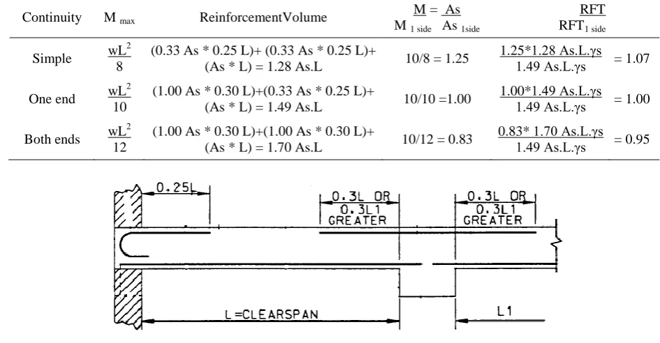
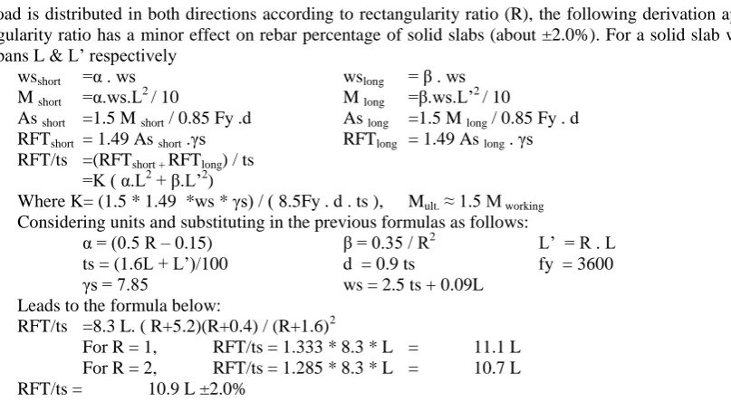
Continuity: Connections between considered bending element and adjacent elements have a major effect on bending moment distribution along this element. As per many codes, maximum bending moment for a simply supported element, one end and both ends continues element subjected to uniformly distributed load are (wL2/8), (wL2/10) and (wL2/12) respectively [1],[4]. Hence, the required reinforcement area for simply supported and both ends continues spans are 1.25 & 0.83 times the required reinforcement area for the one end continues identical span respectively. Also, the continuity of the element affects the detailing of the longitudinal reinforcement. Figure (1) shows the typical detail of solid slabs in ACI-315. Based on this detail the total volume of longitudinal reinforcement are (1.28 As.L), (1.49 As.L) & (1.70 As.L) for the simply supported, one end continues & both ends continues spans respectively, where (As) is the required area of reinforcement steel for each case. Table (1) shows the ratios between reinforcement weight in the three continuity cases and the one end continues case. The ratios are (1.07, 1.00 and 0.95) for the simply supported, one end continues & both ends continues spans respectively. Based on this analysis, all farther analysis will consider the one end continuity with error less than 7%
Table 1: Continuity effect on RFT amount
Continuity M max ReinforcementVolume
.M. = . As. M 1 side As 1side
.
RFT. RFT1 side
Simple wL 2 8
(0.33 As * 0.25 L)+ (0.33 As * 0.25 L)+
(As * L) = 1.28 As.L 10/8 = 1.25
1.25*1.28 As.L.γs
1.49 As.L.γs = 1.07
One end wL 2 10
(1.00 As * 0.30 L)+(0.33 As * 0.25 L)+
(As * L) = 1.49 As.L 10/10 =1.00
1.00*1.49 As.L.γs
1.49 As.L.γs = 1.00
Both ends wL 2 12
(1.00 As * 0.30 L)+(1.00 As * 0.30 L)+
(As * L) = 1.70 As.L 10/12 = 0.83
0.83* 1.70 As.L.γs 1.49 As.L.γs = 0.95
II. SOLID SLABS
Solid slab is the basic type of slabs. It is defined as uniform thickness horizontal concrete plate supported by rigid beams on the edges. Rectangle solid slab is the most common shape, it has four edges, and each edge could be fixed, simply supported or free. According to ACI-318, minimum solid slab thickness meeting deflection requirement could be calculated as follows:
ts = [0.8 + Fy/1600] / [36 + 9 L’/L] (in N,mm)
For Fy=360 MPa, this equation could be simplified to ts= (1.6 L + L’)/100 with error less than 10%, as shown in table(2).
Table 2: Comparison between ACI-318& simplified formulato estimate the thickness of solid slabs
R = L’/ L 1.0 1.2 1.4 1.6 1.8 2.0
ts As ACI-318 L/43.0 L/37.0 L/33.0 L/30.0 L/27.6 L/25.7 (1.6L+L’)/100 L/38.5 L/35.7 L/33.3 L/31.2 L/29.4 L/27.8
Slab load is distributed in both directions according to rectangularity ratio (R), the following derivation approves that rectangularity ratio has a minor effect on rebar percentage of solid slabs (about ±2.0%). For a solid slab with short & long spans L & L’ respectively
wsshort =α . ws wslong = β . ws
M short =α.ws.L2 / 10 M long =β.ws.L’2 / 10
As short =1.5 M short / 0.85 Fy .d As long =1.5 M long / 0.85 Fy . d RFTshort = 1.49 As short .γs RFTlong = 1.49 As long . γs RFT/ts =(RFTshort + RFTlong) / ts
=K ( α.L2 + β.L’2)
Where K= (1.5 * 1.49 *ws * γs) / ( 8.5Fy . d . ts ), Mult. ≈ 1.5 M working Considering units and substituting in the previous formulas as follows:
α = (0.5 R – 0.15) β = 0.35 / R2 L’ = R . L ts = (1.6L + L’)/100 d = 0.9 ts fy = 3600
γs = 7.85 ws = 2.5 ts + 0.09L
Leads to the formula below:
RFT/ts =8.3 L. ( R+5.2)(R+0.4) / (R+1.6)2
For R = 1, RFT/ts = 1.333 * 8.3 * L = 11.1 L For R = 2, RFT/ts = 1.285 * 8.3 * L = 10.7 L RFT/ts = 10.9 L ±2.0%
Similarly, the conclusion is valid in case of two way hollow block slabs.
Solid slabs thicker than 16 cm should have top mesh to resist shrinkage stresses. For 18 cm thick slab, the short span is about 5.0 to 6.0 m according to rectangularity ratio. The top mesh is ranged between 5φ6/m to 5φ10/m for short span between 6.0 to 10.0m. The average weight of the top mesh is about 0.06L2.
A) One way solid slab (L’=2L)
Slab thickness ts (m) = 0.01 (1.6 L + 2 L) = 0.036 L
Slab depth d (m) ≈ 0.032 L
Min. slab thickness = 10 cm, Hence, L min ≈ 3.0 m
Min. RFT weight per m3 (kg/m3) = 12.8 * 3m = 38.5
B) Two way solid slab (L’=L)
For 4 sides supported elastic rectangle plate, α,β=0.35
Slab thickness ts (m) = 0.01 (1.6 L + L ) = 0.026 L
Slab depth d (m) ≈ 0.023 L
Own weight of slab (t/m2) = 0.026L * 2.5 = 0.065 L Total slab load ws (t/m2) = 0.065L + 0.09L = 0.155 L Bending moment in one dir. M (m.t/m’) = α.ws. L2 / 10 = 0.005 L3 Steel area for one dir. As (cm2/m) = 1.5E+5 . M / 0.85 fy.d = 0.118 L2 RFT weight per m2 in one dir. (kg/m2) = 1.49 Asγs = 0.139 L2 Shrinkage RFT weight per m2 (kg/m2) = Avenge value = 0.060 L2 Total RFT weight per m2 (kg/m2) = Sum of weights/m2 = 0.338L2 Total RFT weight per m3 (kg/m3) = 0.338 L2 / 0.026 L = 13.00 L Min. slab thickness = 10 cm, Hence, L min ≈ 4.0 m
Min. RFT weight per m3 (kg/m3) = 13.0 * 4m = 52.0
C) Cantilever solid slab
Slab thickness is about L/10, the main RFT is hook shape, and the upper bars extended 1.5 times cantilever length in the adjacent slab. RFT in secondary direction is 20% of the main steel at top and bottom of the slab.
Slab thickness ts (m) = 0.10 L = 0.10 L
Slab depth d (m) ≈ 0.08 L
Own weight of slab (t/m2) = 0.10 L * 2.5 = 0.250 L Total slab load ws (t/m2) = 0.25L + 0.09L = 0.340 L Bending moment M (m.t/m’) = ws. L2 / 2 = 0.170 L3 Main steel area As (cm2/m) = 1.5E+5 . M / 0.85 fy.d = 1.072 L2 Main RFT weight per m2 (kg/m2) = 3.55 Asγs = 3.000 L2 Sec. RFT area As’ (cm2/m) = 2x20% As = 0.429 L2 Sec. RFT weight per m2 (kg/m2) = 1.00 As’ γs = 0.337 L2 Total RFT weight per m2 (kg/m2) = Sum of weights/m2 = 3.337 L2 Total RFT weight per m3 (kg/m3) = 3.337 L2 / 0.100 L = 33.37 L Min. slab thickness = 10 cm, Hence, L min ≈ 1.0 m
Min. RFT weight per m3 (kg/m3) = 11.1 * 1m = 33.37
III.HOLLOW BLOCK SLABS
Hollow block slab is a ribbed slab formed using blocks of a material lighter than concrete, usually hollow clay blocks or foam blocks. Due to the limitation of the block size, the spacing between ribs is limited by 0.6m (0.5m is commonly used) and the minimum total depth of slab is limited by 20cm. Hollow block slab could be either one way or two ways. Due to the leakage if torsional rigidity and corner effect, Marcos parameters are used to distribute the load in the two ways slabs (α+β=0.80). It is a common practice to evaluate the rebar weight ratio relative to the total thickness of slab. All previous assumptions for solid slab thickness, load and continuity are still valid in case of hollow block slabs in addition to the following assumptions:
Total slab thickness ≈ 1.5 slab thickness of equivalent solid slab
Own weight of one way H.B. slab ≈ 0.5 own weight of equivalent solid slab
Own weight of two ways H.B. slab ≈ 0.66 own weight of equivalent solid slab
Own weight of cantilever H.B. slab ≈ 0.5 own weight of equivalent solid slab
Rib spacing is about 0.5m.
Span is ranged between 5 to 10 m.
Top slab mesh is ranged between φ6-200 to φ10-200, average weight/m2 is 0.075 L2
A) One way hollow block slab
Slab thickness ts (m) = 0.01 (1.6 L + 2 L)x 1.5 = 0.054 L
Slab depth d (m) ≈ 0.050 L
Own weight of slab (t/m2) = 0.054 L * 2.5 * 0.5 = 0.068 L Total slab load ws (t/m2) = 0.068L + 0.09L = 0.158 L Bending moment M (m.t/m’) = ws. L2 / 10 = 0.016 L3 Main steel area As (cm2/m) = 1.5E+5 . M / 0.85 fy.d = 0.160 L2 Main RFT weight per m2 (kg/m2) = 1.49 Asγs = 0.187 L2 Ribs ties weight per m2 (kg/m2) = average value = 0.040 L2 Top slab mesh weight per m2 (kg/m2) = average value = 0.075 L2 Total RFT weight per m2 (kg/m2) = Sum of weights/m2 = 0.300 L2 Total RFT weight per m3 (kg/m3) = 0.300 L2 / 0.054 L = 5.600 L Min. slab thickness = 20 cm, Hence, L min ≈ 4.0 m
Min. RFT weight per m3 (kg/m3) = 5.60 * 4m = 22.5
B) Two way hollow block slab (L’=L)
Using Marcos distribution parameters, α,β=0.40
Slab thickness ts (m) = 0.01 (1.6 L + L)x 1.5 = 0.039 L
Slab depth d (m) ≈ 0.035 L
Own weight of slab (t/m2) = 0.039 L * 2.5 * 0.66 = 0.065 L Total slab load ws (t/m2) = 0.065L + 0.09L = 0.155 L Bending moment in one dir. M (m.t/m’) = α.ws. L2 / 10 = 0.006 L3 Steel area for one dir. As (cm2/m) = 1.5E+5 . M / 0.85 fy.d = 0.089 L2 RFT weight per m2 in one dir. (kg/m2) = 1.49 Asγs = 0.104 L2 Ribs ties weight per m2 (kg/m2) = average value = 0.080 L2 Top slab mesh weight per m2 (kg/m2) = average value = 0.075 L2 Total RFT weight per m2 (kg/m2) = Sum of weights/m2 = 0.365 L2 Total RFT weight per m3 (kg/m3) = 0.365 L2 / 0.039 L = 9.300 L Min. slab thickness = 20 cm, Hence, L min ≈ 5.0 m
Min. RFT weight per m3 (kg/m3) = 9.3 * 5m = 47.0
C) Cantilever hollow block slab
Slab thickness ts (m) = 0.15 L = 0.15 L
Slab depth d (m) ≈ 0.12 L
Own weight of slab (t/m2) = 0.15 L * 2.5 * 0.5 = 0.188 L Total slab load ws (t/m2) = 0.188L + 0.09L = 0.278 L Bending moment M (m.t/m’) = ws. L2 / 2 = 0.139 L3 Main steel area As (cm2/m) = 1.5E+5 . M / 0.85 fy.d = 0.584 L2 Main RFT weight per m2 (kg/m2) = 3.55 Asγs = 1.628 L2 Ribs ties weight per m2 (kg/m2) = average value = 0.040 L2 Top slab mesh weight per m2 (kg/m2) = average value = 0.075 L2 Total RFT weight per m2 (kg/m2) = Sum of weights/m2 = 1.750 L2 Total RFT weight per m3 (kg/m3) = 1.750 L2 / 0.150 L = 11.60 L Min. slab thickness = 20 cm, Hence, L min ≈ 1.5 m
IV.FLAT SLABS
Flat slab is defined as the slab that is supported directly on the columns. It could have uniform thickness (flat plate) or variable thickness (flat slab with dropped panels). Also it could be solid or ribbed (Waffle slab). For uniformly loaded equal spans flat slabs, a simplified design method is stated in most codes depends on calculating the total bending moment in the span and distribute it in both positive and negative in field and column strips according to certain ratios depending of the uniformity of slab thickness and the stiffness of marginal beam.
The considered reinforcement detail is bottom mesh designed for the maximum positive bending moment, top reinforcement above columns designed for the maximum negative moment and extends one sixth the span in both directions and top mesh with area equals to 25% of the top reinforcement above columns (seismic requirement).Unlike the four sides supported slabs, flat & waffle slabs thickness is dominated by the long direction span (L’). Hence, it is better to represent the reinforcement weight per cubic meter as a function of (L’) instead of (L) for flat and waffle slabs.
A) Uniform thickness flat slab
According to simplified design method positive and negative bending moments in column strip could be calculated as follows:
Mo = ws.L12.L2/8,
Column & field strips width = 0.5 L2 M-vemax = 50% Mo (/strip) = ws.L1
2
/ 8 (/m) M+ve max = 30% Mo (/strip) = ws.L12 / 13.3 (/m) Where L1 is the span in considered direction, L2 is the span perpendicular on L1
Slab thickness ts (m) = 0.033 L’
Slab depth d (m) ≈ 0.030 L’
Own weight of slab (t/m2) = 0.033L’ * 2.5 = 0.083 L’ Total slab load ws (t/m2) = 0.083L’ + 0.09L’ = 0.173 L’ For long direction:
Positive bending moment M+ve (m.t/m’) = ws. L’2 / 13.3 = 0.013 L’3 Bottom steel area As (cm2/m) = 1.5E+5 .M+ve / 0.85 fy.d = 0.219 L’2 Bottom RFT weight per m2 (kg/m2) = 1.00 Asγs = 0.172 L’2 Negative bending moment M-ve (m.t/m’) = ws. L’2 / 8 = 0.022 L’3 Top steel area As (cm2/m) = 1.5E+5 . M-ve / 0.85 fy.d = 0.364 L’
2 Top col. RFT weight per m2 (kg/m2) = 0.3 * 0.3 Asγs = 0.026 L’2 Top mesh RFT weight per m2 (kg/m2) = 0.25 * 0.91* Asγs = 0.065 L’2 Total RFT weight per m2 (kg/m2) = Sum of weights/m2 = 0.265 L’2 For short direction:
Positive bending moment M+ve (m.t/m’) = ws. L2 / 13.3 = 0.013 L’L2 Bottom steel area As (cm2/m) = 1.5E+5 .M+ve / 0.85 fy.d = 0.219 L2 Bottom RFT weight per m2 (kg/m2) = 1.00 Asγs = 0.172 L2 Negative bending moment M-ve (m.t/m’) = ws. L2 / 8 = 0.022 L’L2 Top steel area As (cm2/m) = 1.5E+5 . M-ve / 0.85 fy.d = 0.364 L2 Top col. RFT weight per m2 (kg/m2) = 0.3 * 0.3 Asγs = 0.026 L2 Top mesh RFT weight per m2 (kg/m2) = 0.25 * 1.00 Asγs = 0.065 L2 Total RFT weight per m2 (kg/m2) = Sum of weights/m2 = 0.265 L2 Summation of both directions:
Total RFT weight per m2 (kg/m2) = 0.265 L’2 + 0.265 L2 Total RFT weight per m3 (kg/m3) = 0.265 (L’2+L2)/ 0.033 L’
= 8.00 L’. [1 + (L/L’)2] Min. slab thickness = 20 cm, Hence, L=L’ min ≈ 6.0 m
B) Flat slab with dropped panels
For variable thickness flat slab, drop panels extend one sixth the span in both directions are used. Thickness of drop panel is about 1.5 times the slab thickness. According to simplified design method positive and negative bending moments in column strip could be calculated as follows:
Mo = ws.L1 2
.L2/8,
Column strip width = 0.33 L2, field strip width = 0.66 L2 M-vemax =43.3% Mo (/strip) = ws.L12 / 6.15 (/m) M+ve max = 23.3% Mo (/strip) = ws.L12 / 11.4 (/m) Where L1 is the span in considered direction, L2 is the span perpendicular on L1
Slab thickness ts (m) = 0.028 L’
Slab depth d (m) ≈ 0.025 L’
Drop panel thickness td (m) = 0.040 L’ Drop panel depth dd (m) ≈ 0.037 L’
Average thickness tsavg (m) = (0.75 * 0.028 L’ + 0.25 * 0.040 L’) = 0.031 L’
Own weight of slab (t/m2) = 0.031L’ * 2.5 = 0.078 L’ Total slab load ws (t/m2) = 0.078L’ + 0.09L’ = 0.168 L’ For long direction:
Positive bending moment M+ve (m.t/m’) = ws. L’2 / 11.4 = 0.015 L’3 Bottom steel area As (cm2/m) = 1.5E+5 .M+ve / 0.85 fy.d = 0.300 L’2 Bottom RFT weight per m2 (kg/m2) = 1.00 Asγs = 0.230 L’2 Negative bending moment M-ve (m.t/m’) = ws. L’2 / 6.15 = 0.027 L’3 Top steel area As (cm2/m) = 1.5E+5 . M-ve/0.85 fy.dd = 0.344 L’2 Top col. RFT weight per m2 (kg/m2) = 0.3 * 0.3 Asγs = 0.025 L’2 Top mesh RFT weight per m2 (kg/m2) = 0.25 * 0.91* Asγs = 0.061 L’2 Total RFT weight per m2 (kg/m2) = Sum of weights/m2 = 0.316 L’2 For short direction:
Positive bending moment M+ve (m.t/m’) = ws. L2 / 11.4 = 0.015 L’L2 Bottom steel area As (cm2/m) = 1.5E+5 .M+ve / 0.85 fy.d = 0.300 L2 Bottom RFT weight per m2 (kg/m2) = 1.00 Asγs = 0.230 L2 Negative bending moment M-ve (m.t/m’) = ws. L2 / 6.15 = 0.027 L’L2 Top steel area As (cm2/m) = 1.5E+5 . M-ve/0.85 fy.dd = 0.344 L
2 Top col.RFT weight per m2 (kg/m2) = 0.3 * 0.3 Asγs = 0.025 L2 Top mesh RFT weight per m2 (kg/m2) = 0.25 * 0.91* Asγs = 0.061 L2 Total RFT weight per m2 (kg/m2) = Sum of weights/m2 = 0.316 L2 Summation of both directions:
Total RFT weight per m2 (kg/m2) = 0.316 L’2 + 0.316 L2 Total RFT weight per m3 (kg/m3) = 0.316 (L’2+L2)/ 0.031 L’
= 10.2 L’. [1 + (L/L’)2] Min. slab thickness = 20 cm, Hence, L=L’ min ≈ 7.0 m
Min. RFT weight per m3 (kg/m3) = 20.4 * 7.0m = 143
C) Waffle slab
Same criteria of uniform thickness flat slab are considered. Solid part extends one sixth the span in both directions above columns.
Total waffle slab thickness is the same of the equivalent flat slab with dropped panel. Own weight of waffle slab is 0.66 of the equivalent flat slab with dropped panel.
Rib spacing is about 0.8m. Rib ties are ranged between φ6-200 to φ8-200 for spans ranged between 7 to 12 m, hence, the average weight/m2 is about 0.025L2.
Column strip width = 0.33 L2, field strip width = 0.66 L2 M-vemax =43.3% Mo (/strip) = ws.L12 / 6.15 (/m) M+ve max = 23.3% Mo (/strip) = ws.L12 / 11.4 (/m) Where L1 is the span in considered direction, L2 is the span perpendicular on L1
Slab thickness ts (m) = 0.040 L’
Slab depth d (m) ≈ 0.037 L’
Own weight of slab (t/m2) = 0.040L’ * 0.66 * 2.5 = 0.066 L’ Total slab load ws (t/m2) = 0.066L’ + 0.09L’ = 0.156 L’
For long direction:
Positive bending moment M+ve (m.t/m’) = ws. L’2 / 11.4 = 0.015 L’3 Bottom steel area As (cm2/m) = 1.5E+5 .M+ve / 0.85 fy.d = 0.205 L’2 Bottom RFT weight per m2 (kg/m2) = 1.00 Asγs = 0.160 L’2 Negative bending moment M-ve (m.t/m’) = ws. L’2 / 6.15 = 0.025 L’3 Top col. steel area As (cm2/m) = 1.5E+5 . M-ve / 0.85 fy.d = 0.341 L’2 Top RFT weight per m2 (kg/m2) = 0.3 * 0.3 Asγs = 0.024 L’2 Top mesh RFT weight per m2 (kg/m2) = 0.25 * 0.91* Asγs = 0.061 L’2 Rib ties weight per m2 (kg/m2) = Average value = 0.025 L’2 Total RFT weight per m2 (kg/m2) = Sum of weights/m2 = 0.270 L’2 For short direction:
Positive bending moment M+ve (m.t/m’) = ws. L2 / 17.8 = 0.015 L’L2 Bottom steel area As (cm2/m) = 1.5E+5 .M+ve / 0.85 fy.d = 0.205 L2 Bottom RFT weight per m2 (kg/m2) = 1.00 Asγs = 0.160 L2 Negative bending moment M-ve (m.t/m’) = ws. L2 / 5.3 = 0.025 L’L2 Top steel area As (cm2/m) = 1.5E+5 . M-ve / 0.85 fy.d = 0.341 L
2 Top RFT weight per m2 (kg/m2) = 0.3 * 0.3 Asγs = 0.024 L2 Top mesh RFT weight per m2 (kg/m2) = 0.25 * 0.91* Asγs = 0.061 L2 Rib ties weight per m2 (kg/m2) = Average value = 0.025 L2 Total RFT weight per m2 (kg/m2) = Sum of weights/m2 = 0.270 L2
Summation of both directions:
Total RFT weight per m2 (kg/m2) = 0.270 L’2 + 0.270 L2 Total RFT weight per m3 (kg/m3) = 0.270 (L’2+L2)/ 0.040 L’
= 6.75 L’. [1 + (L/L’)2] Min. slab thickness = 25 cm, Hence, L=L’ min ≈ 7.0 m
Min. RFT weight per m3 (kg/m3) = 13.5 * 7.0m = 95
V. CONCLUSION
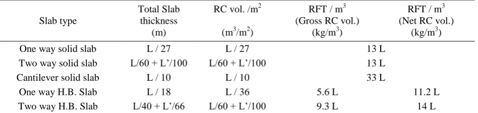
Results of this study could be summarized in the following table:
Table 3: Estimated economic quantities of different concrete slab types (±10%)
Slab type
Total Slab thickness
(m)
RC vol. /m2
(m3/m2)
RFT / m3 (Gross RC vol.)
(kg/m3)
RFT / m3 (Net RC vol.)
(kg/m3)
One way solid slab L / 27 L / 27 13 L
Two way solid slab L/60 + L’/100 L/60 + L’/100 13 L
Cantilever solid slab L / 10 L / 10 33 L
One way H.B. Slab L / 18 L / 36 5.6 L 11.2 L
Cantilever H.B. Slab L / 6.6 L / 13 11.6 L 23 L Uniform thickness flat slab L’ / 30 L’ / 30 8.0 L’. [1 + (L/L’)2]
Flat slab with drop panel L’/ 36&L’/ 24 L’ / 32 10.2 L’. [1 + (L/L’)2]
Waffle slab L’ / 24 L’ / 36 6.75 L’. [1 + (L/L’)2] 10.1 L’. [1 + (L/L’)2]
Where: L & L’ are short & Long span of the slab respectively Values in the table (3) are valid under the following conditions:
- Residential & office building (live load up to 300 kg/m2) - Spans between 4.0 to 12.0 m
- High strength steel ( Fy = 3600 to 4000 kg/cm2)
- Characteristic concrete strength (Fcu = 250 to 350 kg/cm2)
REFERENCES
[1] BS-6399-1-1996, “Loading for buildings-Part 1: Code of practice for dead and imposed loads”, © BSI, ISBN 0-580-26239-1 [2] SEI/ASCE-7-2005, “Minimum Design Loads for buildings and other Structures”, © (ASCE), ISBN 0-7844-0831-9
[3] BS-8110-1-1997, “Structural use of concrete-Part 1: Code of practice for design and construction”, © BSI, ISBN 0-580-26208-1 [4] ACI-318-2005, “Building Code Requirements for Structural Concrete”, © (ACI), ISBN 978-0-87031-745-3.
[5] ACI-315-1999, “Manual of standard practice for detailing reinforced concrete structures”, © (ACI).
[6] BS-CP-110-1987,” Code Of Practice For The Structural Use Of Concrete, Design, materials and workmanship”,© BSI, ISBN 0-580-07488-9 [7] David A. Fanella and S. K. Ghosh, “Simplified Design Reinforced Concrete Buildings of Moderate Size and Height”, © (PCA), ISBN
0-89312-129-0.
[8] R. S. Narayanan & A. Beeby.“Designers' Guide To En 1992-1-1and En 1992-1-2, Eurocode 2: Design Of Concrete Structures General Rules And Rules For Buildings And Structural Fire Design”, © The authors and Thomas Telford Limited 2005, ISBN: 07277 3105 X