R E S E A R C H
Open Access
Achieving low-complexity
maximum-likelihood detection for the 3D
MIMO code
Ming Liu, Matthieu Crussière
*, Maryline Hélard and Jean-François Hélard
Abstract
The 3D Multiple-input multiple-output (MIMO) code is a robust and efficient space-time block code (STBC) for the distributed MIMO broadcasting but suffers from high maximum-likelihood (ML) decoding complexity. In this paper, we first analyze some properties of the 3D MIMO code to show that the 3D MIMO code is fast decodable. It is proven that the ML decoding performance can be achieved with a complexity ofO(M4.5)instead ofO(M8)in quasi-static channel withM-ary square QAM modulations. Consequently, we propose a simplified ML decoder exploiting the unique properties of the 3D MIMO code. Simulation results show that the proposed simplified ML decoder can achieve much lower processing time latency compared to the classical sphere decoder with Schnorr-Euchner enumeration.
Keywords: MIMO; Space-time codes; Maximum-likelihood decoding; Computational complexity
1 Introduction
Multiple-input multiple-output (MIMO) is a promising technique that can bring significant improvements to the wireless communication systems. In combination with space-time block code (STBC), it provides higher spec-trum efficiency with better communication reliability [1]. In the last decades, MIMO has been widely employed in the latest wireless communication standards such as IEEE 802.11n, 3GPP Long Term Evolution (LTE), WiMAX, and Digital Video Broadcasting-Next Generation Handheld (DVB-NGH). It is also seen as the key technology for the future digital TV terrestrial broadcasting standards [2].
A so-called space-time-space (3D) MIMO code [3] was proposed for future TV broadcasting systems, in which the services are delivered by the MIMO transmission in a single-frequency network (SFN). Specifically, it is pro-posed for a distributed MIMO broadcasting scenario, where TV programs are transmitted by two geographi-cally separated transmission sites, each site equipping two transmit antennas. On the other hand, each receiver has two receive antennas, forming a 4×2 MIMO transmis-sion. The 3D MIMO code has been shown to be robust
*Correspondence: [email protected]
Université Européenne de Bretagne (UEB), INSA, IETR, UMR CNRS 6164, 20 avenue des Buttes de Coësmes, Rennes F-35708, France
and efficient in distributed MIMO broadcasting scenarios where there exist strong received signal power imbalances [4]. Hence, it is a promising candidate for MIMO profile of future broadcasting standards. However, the 3D MIMO code suffers from a high computational complexity when the maximum-likelihood (ML) decoding is adopted. The decoding complexity is as high asO(M8)whenM-QAM constellation is used. Up to now, no study on the decod-ing complexity reduction for the 3D MIMO code has been carried out in the literature.
Recently, a lot of efforts have been made in the STBC design to obtain both high code rate and low decod-ing complexity [5-11]. The decoddecod-ing complexity reduction is commonly achieved by exploiting the orthogonality embedded in the STBC codeword. When there exist groupwise orthogonality in the codeword, the joint detec-tion of many informadetec-tion symbols is converted into inde-pendent, groupwise detections [6,10], yielding low decod-ing complexity. For other cases such as DjABBA code [12], Biglieri-Hong-Viterbo (BHV) code [7], Srinath-Rajan code [8], and Ismail-Fiorina-Sari (IFS) code [11] in which the orthogonality only exists in a part of information symbols, some symbols can be detected in a groupwise manner once we condition them with respect to other symbols. Such kind of STBCs are referred to as fast decodable STBCs because they achieve ML decoding performance
with a reduced order of complexity. However, most of the fast decodable STBCs are not optimized for distributed MIMO broadcasting scenarios, and they are not robust under received signal power imbalance conditions [4].
A partial interference cancellation (PIC) group decod-ing scheme has been presented, aimdecod-ing at reducdecod-ing the decoding complexity of the STBCs containing groupwise orthogonalities in the codewords [13,14]. A number of STBCs that are optimized for this decoding scheme have also been proposed [14,15]. This scheme actually uses a linear equalization to convert the joint detection of a large number of symbols to several groups of ML decodings for few symbols. However, the overall performance of this decoding scheme cannot achieve the ML optimality.
Some alternatives with reduced decoding complexity have been presented for the distributed MIMO broad-casting. Polonen and Koivunen described a STBC with less decoding complexity based on orthogonal basis [16]. However, such a code does not achieve full diversity or full rate for 4×2 MIMO transmissions and therefore performs worse than the 3D MIMO code. A ‘punctured version’ of the 3D MIMO code that possesses full rate with low decoding complexity has also been proposed [17]. How-ever, it does not achieve full diversity and is hence less robust in harsh channel conditions.
In this paper, we propose a reduced-complexity ML decoder for the 3D MIMO code which exploits the embedded orthogonality in the codeword. The main con-tributions are as follows:
• We propose to modify the original 3D MIMO codeword through some permutations of
information symbols which lead to an ML decoding algorithm with reduced complexity without affecting all desirable properties of the 3D MIMO code. • We prove that the 3D MIMO code is fast decodable.
Moreover, we show that the worst-case decoding complexity isO(M4.5)forM -ary square QAM modulations which is the least among all square full-rate STBCs for4×2MIMO transmission. • Based on the unique properties of the new form of
3D MIMO codeword, we propose a novel implementation of the simplified decoder that achieves a lower average complexity in terms of time latency without losing the ML optimality. The proposed implementation is also applicable for other fast decodable STBCs.
The remainder of the paper is organized as follows. Some fundamentals of the MIMO detection are presented in Section 2. In Section 3, the 3D MIMO code is first recalled. Consequently, a modification of the codeword is proposed to facilitate the decoding process. Three impor-tant properties of the new codeword are also revealed.
With this knowledge, in Section 4, the ML decoder with a worst-case decoding complexity ofO(M4.5)is derived. Then, in Section 5, a new implementation of the reduced-complexity ML decoder is described. Section 6 presents the symbol error and complexity performance of the new decoder. Conclusions are drawn in Section 7.
1.1 Notations
Vectors and matrices are written in boldface letters. SuperscriptXT represents transposition of matrixX.xR and xI denote the real and imaginary parts of a com-plex numberx, respectively. The operator(ˇ·)performs the complex real conversion fromCtoR2×2: the operation in (1) is performed for all elements xj,k in the matrix, i.e., the (j,k)th 2×2 submatrix of Xˇ isxˇj,k. For a complex vectorx=[x1,x2,. . .,xn]T∈Cn, the oper-ator(˜·)separates the real and imaginary parts of the given vector, i.e.,x [xR1,xI1,. . .,xRn,xIn]T. For a matrix X = [x1,x2,. . .,xn], wherexjis thejth column ofX, the oper-ator vec(X)stacks the columns ofXto form one column vector, i.e., vec(X) [xT1,xT2,. . .,xTn]T. vec(X) denotes vectorizing matrixXfollowed by the real/imaginary part separation. The inner product of two real-valued vectorsx andyis denoted byx,y =xTy. Then×nidentity matrix is denoted byIn. The operator⊗denotes the Kronecker product. Finally,irepresents√−1.
2 System model
2.1 MIMO system model
We consider a MIMO transmission withNttransmit and
Nrreceive antennas over flat fading channel. The received signalY∈CNr×T is
Y=HX+W, (2)
where X ∈ CNt×T is the STBC codeword matrix which is transmitted over T channel uses, W ∈ CNr×T is a complex-valued additive white Gaussian noise (AWGN) component, H ∈ CNr×Nt is the channel matrix whose
(j,k)th element hj,k denotes the channel coefficient of the link between the kth transmit antenna and the jth receive antenna. The channel is assumed to be quasi-static. That is, the channel coefficients keep constant over the duration of one STBC codeword, but change from one codeword to another. Moreover,hj,k’s are assumed to be independent from each other.
For linear STBCs, the codeword matrix X can be obtained through a linear operation [7]:
wheres=[s1,s2,. . .,sκ]Tis the vector containingκ inde-pendent information symbols. The code rate of STBC is κ/Tinformation symbols per channel use. The generator matrixG∈R2NtT×2κis obtained:
G[vec(A1),vec(B1),. . .,vec(Bκ)] , (4)
where Aj ∈ CNt×T andBj ∈ CNt×T are the complex weight matrices representing the contribution of the real and imaginary parts of thejth information symbolsjin the final codeword matrix.
Separating the real and imaginary parts of the transmit-ted and received signals and stacking the columns of the codeword, the received MIMO signal (2) can be expressed in an equivalent real-valued form:
y=Heqs+w, (5)
wherey=vec(Y)andw=vec(W), andHeq ∈R2NrT×2κ is the equivalent channel matrix and is obtained by
Heq=(IT ⊗ ˇH)G. (6)
Note that the real-valued expression of the signal can be obtained from the complex-valued form via a lin-ear transform. Hence, we will jointly use both real- and complex-valued forms in the sequel.
2.2 ML decoding of MIMO signals
Once the channelHeqis known by the receivera, the infor-mation symbols can be retrieved from the received signal yin (5). The ML solution of the transmitted signal is the combination of information symbolss =[s1,s2,. . .,sκ] that minimizes the Euclidian distance between the chan-nel distorted information signalHeqsand received signal y, namely
ˆ
sML=arg min
s∈κy−Heqs
2, (7)
whereis the set of the constellation symbols. (7) indi-cates that the ML solution is found byjointly determin-ingκ independent information symbols. In other words, when the modulation of these symbols isM-QAM, the ML decoding should exhaustively check all Mκ combi-nations. The search complexity grows dramatically with higher modulation order or larger number of informa-tion symbols in one codeword. Hence, the ML decoding is computationally demanding.
2.3 Fast ML decoding of MIMO signals
More efficient STBC decoding is achieved with the help of orthogonal-triangular (QR) decomposition [7,18]. The QR decomposition of the equivalent channel matrixHeq yields Heq = QR, where Q ∈ R2NrT×2κ is a unitary matrix, andR ∈ R2κ×2κ is an upper triangular matrix.
The detailed definitions of the elements inQandRcan be found in the Appendices. Instead of solving (7), the ML solution can be alternatively found by
ˆ
sML=arg min
s∈κ∩Sz−Rs
2, (8)
wherez = QTy is a linear transformation of received signal andz ∈ R2κ;S is a hypersphere centered on the received signal. Only the codewords inside the hyper-sphere are checked during the search in order to reduce the search complexity. The size of the hypersphere is rep-resented by its radius. The decoding process is turned into a bounded search over aκ-level tree with complex-valued nodes. Hence, the worst-case decoding complexity isO(Mκ).
Moreover, according to the property of the QR decom-position, some information symbols can be decoded inde-pendently from the others if some elements of R are equal to zero. It suggests that the joint search in a high dimension is converted into a bunch of parallel, indepen-dent searches in low dimensions. This results in a sig-nificant reduction of the worst-case decoding complexity [7,8,19].
3 3D MIMO code
In this section, we propose a new 3D MIMO codeword that enables low sphere decoding complexity via exchang-ing the positions of information symbols in the original 3D MIMO codeword. The basic idea behind this modification comes from the facts that the orthogonality embedded in the information symbols essentially enables independent detections and the sphere decoding complexity is mainly determined by the orthogonality among the first several symbols. Hence, exploiting the underlying orthogonal-ity in the codeword and carefully choosing the sequence of information symbols can bring benefits in terms of decoding complexity.
3.1 A new proposal of the 3D MIMO codeword
The initially proposed codeword matrix of the 3D MIMO code is explicitly written as
X3D=
Xgolden,1 −X∗golden,2 Xgolden,2 X∗golden,1
Xgolden,2, which are consequently arranged in an Alam-outi manner [21] over four channel uses (T = 4)b. This results in a code rate of 2 which isfull ratefor the 4×2 MIMO transmission. Previous study shows that the 3D MIMO code achieves efficient and robust performance. However, since eight information symbols are stacked in one codeword, the ML decoding complexity is up to O(M8).
It was shown that it is possible to achieve lower sphere decoding complexity through permuting the sequence of information symbols [22]. We propose to slightly modify the codeword by exchanging the positions of informa-tion symbols (s3,s4) and(s5,s6), yielding a new form of codeword:
X3D,new
= √1 5
⎡ ⎣α(
s1+θs2) α(s5+θs6) −α∗(s3∗+θs∗4) −α∗(s∗7+θs∗8) iα(¯s5+ ¯θs6) α(¯s1+ ¯θs2) iα¯∗(s∗7+ ¯θs∗8) −¯α∗(s∗3+ ¯θs∗4)
α(s3+θs4) α(s7+θs8) α∗(s1∗+θs∗2) α∗(s∗5+θs∗6) iα(¯s7+ ¯θs8) α(¯s3+ ¯θs4) −iα¯∗(s∗5+ ¯θs∗6) α¯∗(s∗1+ ¯θs∗2)
⎤ ⎦.
(10)
Since we only change the sequence of the information symbols in the codeword (the third and fourth infor-mation symbols become the fifth and sixth, respectively, and vice versa) and the information symbols are inde-pendent from each other, the new codeword preserves all the good attributes of the original 3D MIMO code in distributed MIMO scenarios. More importantly, this modification is based on the embedded orthogonalities in the 3D MIMO codeword and yields an interesting code-word structure which will be exploited to achieve lower decoding complexity. The advantages brought by the new codeword structure will be highlighted in the following sections.
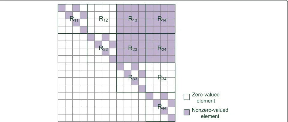
3.2 Key properties of the proposed 3D MIMO codeword Due to the underlying Alamouti and golden structures, the 3D MIMO code has some unique properties which lead to simplified decoding algorithms. For the modified 3D MIMO code (10) over a 4×2 MIMO channel, theR matrix in (8) is a 16×16 real-valued matrix. RewriteRin a block-wise form:
R=
⎡ ⎢ ⎢ ⎣
R11 R12 R13 R14
0 R22 R23 R24 0 0 R33 R34
0 0 0 R44
⎤ ⎥ ⎥
⎦, (11)
where Rjk’s are 4× 4 submatrices containingqm,hn’s withm=4(j−1)+1,. . ., 4jandn=4(k−1)+1,. . ., 4k. Based on the new codeword in (10) and taking into account (6), (3), and (4), we obtain a few interesting prop-erties of R that can be made use of to achieve a low decoding complexity.
Theorem 1. R11 is an upper triangular matrix with
q1,h2 = q1,h4 = q2,h3 = q3,h4 =0.
Theorem 2. R12 is a null matrix when the channel is
quasi-static, i.e., qj,hk = 0, ∀j = 1, 2, 3, 4, and k = 5, 6, 7, 8.
Corollary 1. R22 is an upper triangular matrix with
similar structure as R11, i.e., q5,h6 = q5,h8 =
q6,h7 = q7,h8 =0.
The proofs of Theorem 1, Theorem 2, and Corollary 1 are presented in the Appendices. The above properties are visualized in Figure 1.
Remark 1.Theorem 1 and Corollary 1 actually suggest the independency between real and imaginary parts of the information symbols. For instance,q1,h2 = q1,h4 =
q3,h4 =0 means that the real parts of the first and sec-ond received symbols, namelyz(1)andz(3), do not con-tain any contribution fromsI1andsI2. Similarly,q2,h3 = 0 means that their imaginary parts, namelyz(2)andz(4), do not contain any contribution fromsR1andsR2, either. As we will show later, this real/imaginary independency leads to independent and parallel detections for real part and imaginary part, respectively.
The real/imaginary part independency comes from the underlying golden and Alamouti structures. It has been revealed that the complex-valuedRmatrix of the golden code has a real upper left submatrix [19], which coincides with the structure as presented in Theorem 1. It shows the real/imaginary part independency of the golden code in its 2×2 codeword matrix. The Alamouti-like arrangement of the two golden codewords, on the other hand, helps create this independency in the 4×4 codeword matrix of the 3D MIMO code.
Remark 2.Theorem 2 indicates that some parts of the information symbols are uncorrelated with others in the received symbols. More precisely, the first two received complex symbols, or equivalentlyz(1),z(2),z(3), andz(4), do not contain any contribution from information sym-bolss3ands4. Hence, a group of six information symbols
s1,s2,s5,s6,s7, ands8can be jointly determined, regardless of the values ofs3ands4. It means that the ML decoding can be achieved by joint searches over six, instead of eight, information symbols. In other words, the ML decoding
complexity is expected to be O(M6) instead of O(M8). Therefore,the 3D MIMO code is fast decodable.
It should be noted that Theorem 2 is partially enabled by the embedded Alamouti structure in the codeword. The channel coefficients should be constant within the dura-tion of one codeword to validate the orthogonalities in the Alamouti structure. Hence, Theorem 2 is only valid in the quasi-static channelsc.
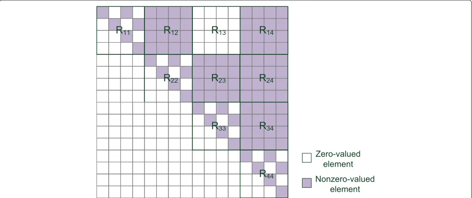
3.3 Comparison with the original 3D MIMO codeword Figure 1 illustrates the Rmatrix of the new 3D MIMO codeword. Compared with the original one as shown in Figure 2, the new structure is actually more favorable for the MIMO decoding. In the new codeword, the contribu-tions of information symbol groups(s1,s2)and(s3,s4)are totally uncorrelated in the received signal, which means that the ML detection of eight information symbols can be achieved by two independent and less complex detec-tions of six information symbols. Moreover, the structures ofR11andR22enable the independent detections of real and imaginary parts of(s1,s2)and(s3,s4), which leads to further complexity reduction. Yet, this real/imaginary part separation is not straightforward in the original codeword. It should be emphasized that the new codeword only changes the sequence of the information symbols in the codeword to facilitate the decoding process. It does not affect all the good properties of the 3D MIMO code.
4 Proposed ML decoder with low complexity In this section, a low-complexity ML decoding algo-rithm exploiting the unique properties highlighted in the previous section is proposed for the 3D MIMO code.
Generally speaking, the complexity reduction is achieved in two steps. Based on Theorem 2, the joint detection of eight information symbols is converted into two partially independent detections of six information symbols. This step reduces the worst-case decoding complexity from O(M8) to O(M6). Consequently, using Theorem 1 and Corollary 1, the detections of complex information sym-bols are converted into independent detections of real and imaginary parts, which further reduces the worst-case complexity toO(M4.5).
4.1 Groupwise parallel detections
We divide the information symbols and received symbols into four groups, i.e.,a = [s1,s2]T, b = [s3,s4]T, c =
[s5,s6]T,d = [s7,s8]T, z12 = [z1,z2]T,z34 = [z3,z4]T, z56 = [z5,z6]T, andz78 = [z7,z8]T. Taking into account the structure ofRand Theorem 2, the decoding metric in (8) can be rewritten as
z−Rs2= z12−R11a−R13c−R14d2 (12) + z34−R22b−R23c−R24d2 (13) + z56−R33c−R34d2+ z78−R44d2. From (12) and (13), it can be seen that the contributions from the information symbol groupsaandbare uncor-related in the received symbol. For instance,z12does not contain any information fromb, and z34 is irrelevant to a, either. This enables us to use groupwise conditional detections to retrieve the ML solutions [23].
In particular, the ML solution ˆsML =[aˆ,bˆ,ˆc,dˆ]T is achieved in two search steps, namely, a joint ‘outer’ search for [ˆc,dˆ]:
and two independent ‘inner’ searches for aˆ and bˆ, respectively: outer search is carried out over the combinations of [c,d]. For a given [c,d], the search ofaand the search ofbare performed in parallel. The concatenation of the outer and
inner searches (eitheraorb) results in a joint search of six information symbols. Therefore, the worst-case decod-ing complexity is reduced from O(M8) to O(M6). We note that this complexity reduction does not rely on the constellation that is adopted by the information symbols. In other words, the 3D MIMO code requires a worst decoding complexity ofO(M6)for arbitrary modulation.
4.2 Independent detections of real and imaginary parts If square-shape QAM modulations are considered, the decoding complexity can be further improved. The square M-QAM symbol can be separated into two indepen-dent√M-PAM symbols on the real and imaginary axes, respectively. Using Theorem 1 and Corollary 1, the real and imaginary parts can be decoded separately. Take the detection ofa as an example. Denote its real and imagi-nary parts asaR=[sR1,sR2]TandaI=[sI1,sI2]T, respectively. Given [c,d] and using Theorem 1, the detection ofain (16) is rewritten as [19]
ˆ
where is the set of √M-PAM constellation symbols. vR12 =[vR1,vR2]T, andvI12 =[vI1,vI2]T;RR11 andRI11 are tai-lored upper triangular matrices associated with real and imaginary parts, respectively:
(18) means that the detections of real and imaginary parts are similar and can be performed separately. Take the real part as an example. We apply again the conditional detection here. For a givensR2, the metric for the real part detection becomes
vR12−RR11aR2=wR1−R11(1, 1)sR12+(wR2)2, (20)
sR1=Q
where Q(·) is the slicing operation providing the PAM symbol that is closest to the given value. The best com-bination of [ˆsR1,ˆsR2]T given [c,d] is obtained after testing
Consequently,ˆsR1 is obtained by using the solutionˆsR2 in (21). Similar process can be applied to solve the imagi-nary parts. The best solution of [ˆsI1,ˆsI2]Tgiven [c,d] can Using the same technique, the best solutions ofbin (17) can also be converted into independent detections ofbR andbI. SubstitutingR
11, v1, v2, s1, and s2 in (21), (22), (23), and (24) by R22, v3, v4, s3, and s4, respectively, it yields the detections fors3ands4. In general, for a given [c,d], the search of two complex symbols [a,b] is turned into four independent searches of√MPAM symbols. The resulting overall complexity to decode a whole codeword isO(M4.5).
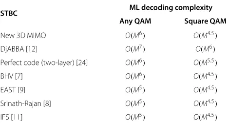
In summary, the 3D MIMO code requires a worst decoding complexity of O(M6) for any modulation scheme and O(M4.5) for square M-QAM modulations. The comparisons with other state-of-the-art fast decod-able STBCs that are full rate for 4×2 MIMO transmissions are presented in Table 1. It can be seen that the 3D MIMO code is among the simplest full-rate STBCs when the square QAM modulations are considered.
5 Proposed implementation of the simplified ML decoder
In the previous sections, we have illustrated the fast decodability of the 3D MIMO code in theory. With this knowledge, we propose an implementation of the sim-plified ML decoder that can be used in practice. Using the two-stage tree search structure and leveraging the symmetry structure in the codeword, the proposed imple-mentation requires a low average complexity in practice. Moreover, various performance complexity trade-offs can be easily achieved by replacing the sphere decoder by
Table 1 Comparison of ML decoding complexities of STBCs
for 4×2 MIMO transmission
STBC ML decoding complexity
other suboptimal tree search algorithms such as K-best algorithm [25] and fixed-complexity sphere decoder [26].
5.1 Two-stage decoding structure
Recall that the fast decodability is achieved by concatenat-ing the joint search of four complex symbols and several detections in parallel. Figure 3 presents the general struc-ture of the proposed simplified ML decoder. A detailed pseudocode is presented in Algorithms 1, 2, 3, and 4 so that the proposed decoder can be implemented without major effort.
Algorithm 1: Simple ML decoder for 3D MIMO
code.
5.1.1 Four-level tree search phase
The joint detection of [c,d] is realized by a com-plex sphere decoder with Schnorr-Euchner enumeration, which is visualized by the search over a four-level tree as shown in Figure 3. The nodes of the same level represent all the solutions of a complex information symbol. Each path from the root to a leaf node represents a possible combination of [c,d].
Algorithm 2:Simple ML decoderSimpML.
6 ifdnew<radiusthen % inside sphere
7 ifl=1then % tree search phase
8 runSimpML(z,R,sˆ,s, radius,l−1,dnew,
); % check lower layer
9 else % leaf node found
10 cˆ =s(1 : 4),dˆ =s(5 : 8);
11 computev1,v2,v3andv4;
12 runParaDec(v1,v2,v3,v4,R,radius,
dnew); % parallel decision phase
13 dt=dp+dnew; % overall distance
14 ifdt<radiusthen % better solution found
15 sˆ=[aˆ,bˆ,cˆ,dˆ]T; 16 radius=dt;
Algorithm 3:Parallel decision algorithmParaDec.
Input:v1,v2,v3,v4,R, radius,d
14 break; % terminate if all branches stop
15 repeat lines 7 to 12 forsI2,sR4andsI4; 16 ifflag1==1then
17 sR1 =Q((vR1−R11(1, 3)sR2)/(R11(1, 1)));
18 τ1= |vR1−R11(1, 1)sR1−R11(1, 3)sR2|2+τ1; % current distance of the branch
19 ifτ1<p1then
20 sˆR1 =sR1,ˆsR2=sR2 ; % current best solutions
21 p1=τ1; % current minimum branch
distance
22 repeat lines 16 to 21 for other branches;
23 aˆ=[ˆsR
1,ˆsI1,sˆR2,sˆI2],bˆ =[sˆR3,ˆsI3,sˆR4,ˆsI4] ; % best solution
24 dp=d1+d2+d3+d4;% overall distance of[sˆ1,. . .ˆs4]T
Algorithm 4:Column switch algorithmColSwt.
Input:sZF,Heq Output:−→Heq,−→sZF 1 computejk’s ;
2 if14< 58 then % decode[s5,. . .s8]by tree search 3 −→s =[s1,s2,s3,s4,s5,s6,s7,s8] ;
4 if78< 56then% valid only in 2-by-2 column switch 5 −→s =[s3,s4,s1,s2,s7,s8,s5,s6] ;
6 else % decode[s1,. . .s4]by tree search
7 −→s =[s5,s6,s7,s8,s1,s2,s3,s4] ;
8 if34< 12then% valid only in 2-by-2 column switch 9 −→s =[s7,s8,s5,s6,s3,s4,s1,s2] ;
10 permutesZFandHeqaccording to−→s; 11 returnpermutation results−→Heq,−→sZF.
hypersphereS. For the node under checking, the partial distance resulted by the current path is compared with the radius. If the partial distance is smaller than the radius, the search moves on to the children nodes on the next level. Otherwise, the search jumps to another sibling node on the current level. When all the nodes of the level have already been checked, the search goes back to the upper level. The radius is initially set to infinity and is adaptively decreased according to the best solution already found in the search. Specifically, the radius is updated, taking into account the best combination of [c,d], and [a,b] (line 16 of Algorithm 2). The latter is obtained from the parallel decisions phase. The tree search is terminated when all the nodes within the hypersphere have been checked. The best solution is the ML solution.
The sequence in which the sibling nodes are visited is determined according to the their partial distances in an ascending order. This is to guarantee that the promis-ing candidates are visited first in order to reduce the search complexity. This ordering process is referred to as the Schnorr-Euchner enumeration [18,27,28]. It can sim-ply be implemented by a lookup table [29,30] (line 4 in Algorithm 1), and its complexity is merely the computa-tion of the linear estimacomputa-tionˆsZF.
5.1.2 Parallel decision phase
Once a leaf node is achieved in the tree search, a better solution of [c,d] is found. Consequently, the tree search process is suspended, and the new [c,d] is used to trigger the parallel detections of the rest symbols.
Figure 3Two-stage sphere decoding.
detections in the different branches are synchronized by a common clock signal because the operations are exactly the same for all branches. All branches simultaneously check the first candidate PAM symbol and then move on to the second one, and so on.
Moreover, we propose a mechanism that terminates the search in each branch not only based on its own results but also taking into account the results from the other branches. In particular, once the best solution of thejth branch is found ahead of the others, the resulting branch distancedjis recorded and shared with other branches to speed up the overall search process.
Take the search of the first branch as an example. The most promising PAM symbol in the unchecked symbol list
is assigned tosR2 (line 8 in Algorithm 3). The partial dis-tanceτ1is calculated (line 9 in Algorithm 3). The search is terminated in two cases: (a) if this partial distance is greater than the current minimum branch distance (τ1> p1) and (b) if the overall distance is beyond the current radius of the sphere decoder in the tree search phase ((τ1+d2+d3+d4+d) >radius).
Once the searches on all the branches are terminated, the solution [a,b] and the resulting distance dp are returned to the tree search phase. The tree search process is resumed. The overall distance is compared with the cur-rent radius (line 14 in Algorithm 2) to determine whether the current solution is a better one. If a better solution is found, the radius is updated accordingly (line 16 in
S-E
enumeration
1
stchoice
2
ndchoice
3
rdchoice
4
thchoice
found
update d
3found
update d
4found
update d
1found
update d
2]
,
R R2
1
s
[s
]
,
I I2 1
s
[s
]
,
R R4
3
s
[s
] , I I
4
3 s
[s
]
,
RR 2
1
v
[v
]
,
I I 21
v
[v
, R]R
4 3 v
[v I
,
I]
4 3
v
[v
Figure 4Parallel decisions of[sR
Algorithm 2). The tree search process is moved on to the next unchecked node.
5.2 Column switch based on ZF estimation
In the proposed algorithm, the search of eight sym-bols is divided into a tree search for four symsym-bols and parallel detections for the other four symbols. Due to the symmetric structure of the codeword matrix (10), some parts of the codewords can be exchanged with-out changing the properties of the 3D MIMO code. For instance, we have the same properties as illus-trated in Section 3 after exchanging the positions of [s1,s2,s3,s4] with [s5,s6,s7,s8]. Similarly, if we exchange [s1,s2] with [s3,s4] and exchange [s5,s6] with [s7,s8] simultaneously, the structure of R matrix maintains, as well. That is to say, besides the original symbol sequence, the proposed low-complexity decoding algorithm is also valid with other three permuted symbol sequences, i.e., [s5,s6,s7,s8,s1,s2,s3,s4], [s3,s4,s1,s2,s7,s8,s5,s6], and [s7,s8,s5,s6,s3,s4,s1,s2].
The exchanging of the symbol sequences can be achieved by permuting the corresponding columns in the equivalent channel matrixHeq. Note that the aforemen-tioned column permutations do not affect the decoding performance. This permits us to choose the symbols that will be determined by the tree search and the ones that will be decoded in the parallel detections.
The proposed column switch method is presented in Algorithm 4. The basic idea is to use the tree search to determine the more difficult half part and use the parallel detections to find the easier half part. The reason behind this idea is that the parallel decoding is more efficient to decode the reliable symbols separately. The more accu-rate the linear estimation, the faster is the convergence speed for each individual detection branch. On the other hand, the tree search phase is a joint serial detection in nature which is more suitable to decode those unreliable symbols.
The next question is how to properly choose the unre-liable symbols. In the literature, Barbero and Thomp-son proposed to sort the decoding sequence based on the norm of subchannels in the fixed-complexity sphere decoder [26]. However, it is not applicable here because the 3D MIMO code achieves full diversity, and the equiv-alent subchannels have similar norm values. In addition, as we have to maintain the structure of theRmatrix, the unconstrained subchannel sorting proposed in [29] is not applicable, either.
Alternatively, we propose to sort the information sym-bols according to the aggregate error of the linear estimation:
wheresZF = H†eqyis the unconstrained estimation of the information symbols in whichH†eqrepresents the inverse of the equivalent channel matrix;sˆZF =Q(sZF)is the con-stellation point that is closest to sZF. The metric is the distance between the estimated information symbols and the nearest constellation points, i.e., an indicator of the estimation accuracy.
Using (25), the decoding sequence can be determined in two levels. We first compare the aggregate errors of the first half and second half parts of the symbols (line 2 in Algorithm 4). The half with worse accuracy is assigned to the tree search (put in the latter part of the decod-ing sequence). Consequently, within this half part, the errors of the first two symbols and the second two are compared. The two symbols with worse accuracy are put closer to the root of the tree. If this two-symbol-by-two-symbol exchange takes place in the second half of the symbols which are to be decoded using the tree search, the same two-symbol-by-two-symbol exchange should be done accordingly in the other half in order to maintain the structure of the R matrix. If only the symbol exchange between the two halves of the sym-bols is carried out, it is referred to as ‘4-by-4 column switch’. Otherwise, if the exchange within each half is also performed, it is called ‘2-by-2 column switch’. The advantage of the column switch will be shown in the next section.
6 Simulation results
6.1 BER performance
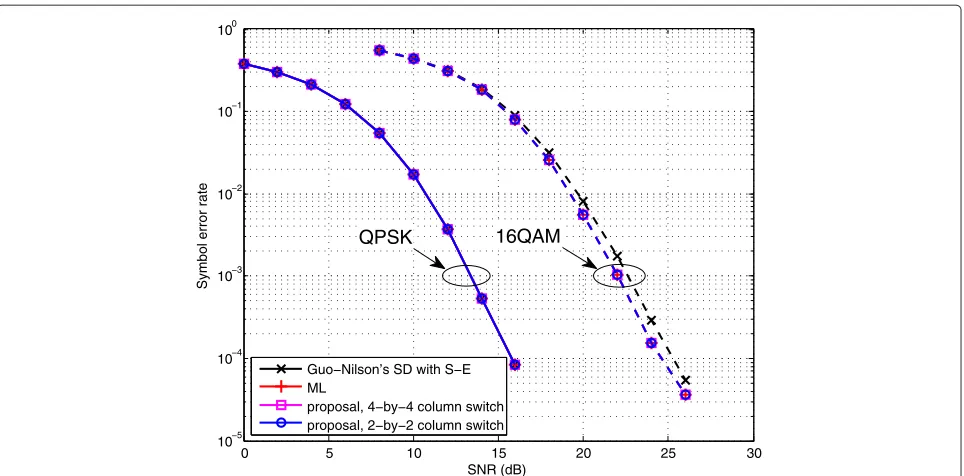
Figure 5 presents the uncoded symbol error rate of the proposed simplified decoders in quasi-static independent Rayleigh flat fading channel. The performances of the ML decoder and the sphere decoder with Schnorr-Euchner (S-E) enumeration proposed by Guo and Nilsson [28] are also given as references. The Guo-Nilsson sphere decoder is a low-complexity implementation of sphere decoder with S-E but is sub-optimal in terms of symbol error rate. It can be seen that the proposed decoders achieve the same per-formance as ML decoder with both QPSK and 16-QAM modulations. In addition, the proposed decoders out-perform the Guo-Nilsson sphere decoder with 16-QAM modulation. A gain of around 0.7 dB can be observed at symbol error rate level of 1×10⁻⁴.
6.2 Computational complexity
0 5 10 15 20 25 30 10−5
10−4 10−3 10−2 10−1 100
SNR (dB)
Symbol error rate
Guo−Nilson’s SD with S−E ML
proposal, 4−by−4 column switch proposal, 2−by−2 column switch
16QAM QPSK
Figure 5Symbol error rate comparison.Uncoded symbol error rate obtained with the Guo-Nilsson sphere decoder with S-E for 3D MIMO code, ML decoder, and the proposed simplified ML decoders in quasi-static Rayleigh channel with QPSK and 16-QAM.
for both decoders, these experiments actually give the comparison of the processing time latency [19,28]. It can be seen from the results that the proposed decoders require much less processing time than the ML decoder which needs to traverse allM8possibilities. In the QPSK case, the proposed decoders always yield less latency
than the Guo-Nilsson sphere decoder. For instance, the proposed decoder with the 2-by-2 column switch visits only 254.6 nodes on an average at SNR of 0 dB. Com-pared with the Guo-Nilsson decoder which visits 1276.6 nodes at SNR of 0 dB, the proposed one achieves a pro-cessing time reduction of 80%. The reductions are 50%
0 2 4 6 8 10 12 14 16 18 20
101 102 103 104
SNR (dB)
Visited nodes (time latency)
Guo−Nilson’s SD with S−E proposal, no column switch proposal, 4−by−4 column switch proposal, 2−by−2 column switch
8 10 12 14 16 18 20 22 24 26 28 101
102 103 104
SNR (dB)
Visited nodes (time latency)
Guo−Nilson’s SD with S−E proposal, no column switch proposal, 4−by−4 column switch proposal, 2−by−2 column switch
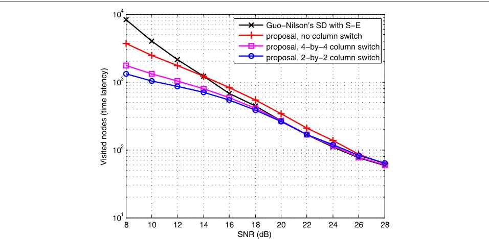
Figure 7Complexity in terms of the visited nodes with 16-QAM.Computational complexity in terms of the visited nodes required by Guo-Nilsson sphere decoder with S-E for 3D MIMO code and proposed simplified ML decoders, in quasi-static Rayleigh channel with the 16-QAM modulation.
and 49% at 10 and 20 dB, respectively. In addition, the improvements brought by the proposed column switch technique can also be seen in the results. For instance, the 2-by-2 column switch yields a processing time reduc-tion of 38% at 0 dB compared with the decoder without column switch. This improvement is less significant in high-SNR region (e.g., greater than 15 dB). In the 16-QAM case (see Figure 7), the proposed decoder with the 2-by-2 column switch also brings processing time reduction in low-SNR region. At 8 dB, it visits 1301.1 nodes on aver-age, yielding a time reduction of 84% compared with the Guo-Nilsson decoder. The proposed decoder needs sim-ilar time latency as the Guo-Nilsson decoder in higher-SNR region (e.g., greater than 15 dB). Taking into account the symbol error rate performance given in Figure 5, 8 ∼ 15 dB is the SNR range where the error correction abil-ity of the channel coding will be carried out significantly. That is to say, the improvements are achieved in a SNR region of interest.
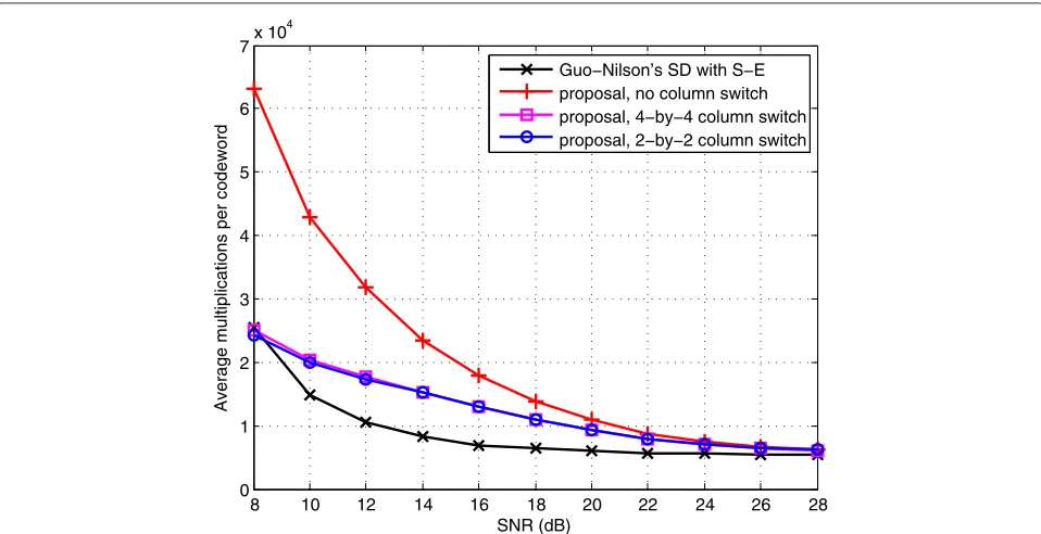
Figures 8 and 9 give the overall required multiplications to decode each codeword. For the proposed decoders, the multiplications spent by the tree search and by all the four search branches are taken into account. The compu-tation overheads such as the QR decomposition and the linear estimation are also included in the results to give the overall complexity of the decoders. It can be seen from the results that in the QPSK case, the proposed decoder with the 2-by-2 column switch spends 11%, 21%, and 3% more multiplications than the Guo-Nilsson decoder at a
SNR of 0, 6, and 20 dB, respectively. In the 16-QAM case, it needs 5% less multiplication at 8 dB but spends 85% and 9% more multiplications at 14 and 28 dB, respectively. However, it is worth noting that with the cost of increased multiplications, the proposed decoders provide less pro-cessing latencies. For instance, the proposed decoder with the 2-by-2 column switch achieves 62% processing time reduction at SNR of 6 dB with QPSK and 42% reduction at 14 dB with 16-QAM, respectively.
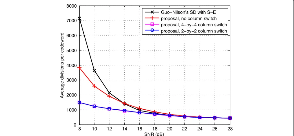
Finally, Figures 10 and 11 present the overall divisions spent by the decoders. The proposed decoders require less divisions than the Guo-Nilsson. For instance, the pro-posed decoder with the 2-by-2 column switch requires 47%, 9%, and 5% less divisions at SNR of 0, 10, and 20 dB, respectively, with QPSK. In the 16-QAM case, it achieves 79% reduction of divisions at 8 dB. In the meantime, the two decoders spend roughly the same number of divisions in higher-SNR region, e.g., greater than 18 dB.
In general, we can see the different trade-offs achieved by the different decoders. The proposed decoder achieves ML performance with less time latency and less divi-sions than the Guo-Nilsson. On the other hand, the Guo-Nilsson decoder needs less multiplications with some performance loss with 16-QAM.
7 Conclusion
0 2 4 6 8 10 12 14 16 18 20 5000
6000 7000 8000 9000 10000 11000 12000 13000
SNR (dB)
Average multiplications per codeword
Guo−Nilson’s SD with S−E proposal, no column switch proposal, 4−by−4 column switch proposal, 2−by−2 column switch
Figure 8Complexity in terms of multiplications with QPSK.Computational complexity in terms of multiplications required by the Guo-Nilsson sphere decoder with S-E for 3D MIMO code and proposed simplified ML decoders, in quasi-static Rayleigh channel with the QPSK modulation.
first proposed a new form of the the 3D MIMO code-word and investigated some important properties of the new codeword. With these properties, the 3D MIMO code is proven to be fast decodable. Consequently, we proposed a reduced-complexity ML decoder for the 3D
MIMO code which offers the same performance as that of the ML decoder. The simulation results demonstrate that the novel low-complexity decoder yields much less pro-cessing time latency than the classical Guo-Nilsson sphere decoder with Schnorr-Euchner enumeration. Moreover,
8 10 12 14 16 18 20 22 24 26 28
0 1 2 3 4 5 6 7x 10
4
SNR (dB)
Average multiplications per codeword
Guo−Nilson’s SD with S−E proposal, no column switch proposal, 4−by−4 column switch proposal, 2−by−2 column switch
0 2 4 6 8 10 12 14 16 18 20 300
400 500 600 700 800 900 1000 1100 1200 1300
SNR (dB)
Average divisions per codeword
Guo−Nilson’s SD with S−E proposal, no column switch proposal, 4−by−4 column switch proposal, 2−by−2 column switch
Figure 10Complexity in terms of divisions with QPSK.Computational complexity in terms of divisions required by the Guo-Nilsson sphere decoder with S-E for the 3D MIMO code and proposed simplified ML decoders, in quasi-static Rayleigh channel with the QPSK modulation.
the proposed 2-by-2 column switch technique can signifi-cantly reduce the average decoding complexity, especially with the 16-QAM modulation.
Endnotes
aWe assume that the receiver has perfect knowledge of
the channel in our work. In practice, the channel
coefficients should be estimated using some channel estimation techniques.
bNote that this construction is different from those of
the quasi-orthogonal code [5] and the EAST code [9].
cThe fast decodability of the other STBCs such as
DjABBA, BHV, Srinath-Rajan, and IFS codes also requires quasi-static channel assumption.
8 10 12 14 16 18 20 22 24 26 28
0 1000 2000 3000 4000 5000 6000 7000 8000
SNR (dB)
Average divisions per codeword
Guo−Nilson’s SD with S−E proposal, no column switch proposal, 4−by−4 column switch proposal, 2−by−2 column switch
Appendix
Definition of the QR decomposition
If we writeHeq =[h1,. . .,h2κ], theHeq’s QR decomposi-tionHeq = QRis achieved by Gram-Schmidt procedure such thatQ [q1,. . .,q2κ], where the columns qj’s are
Based onHeq, after some straightforward computation, it yieldsh1,h2 = h1,h4 = h2,h3 = h3,h4 = 0. According to the definition of QR decomposition,q1 = h1/h1. Hence,q1,h2 = q1,h4 =0. This completes the proof of Theorem 1.
Proof of Theorem 2
Based onHeq, after some straightforward computation, it yieldshj,hk =0,∀j= 1, 2, 3, 4, andk =5, 6, 7, 8. Using
This completes the proof of Theorem 2.
Proof of Corollary 1
Using the similar method as in the proof of Theorem 1, it can be computed from the definition of Heq that
h5,h6 = h5,h8 = h6,h7 = h7,h8 =0. In addition,
This completes the proof of Corollary 1.
Competing interests
The authors declare that they have no competing interests.
Acknowledgements
This work has been supported by French ANR ‘Mobile Multi-Media (M3)’ project and ‘Pôle Images & Réseaux’.
Received: 15 July 2013 Accepted: 9 January 2014 Published: 1 February 2014
References
1. V Tarokh, N Seshadri, A Calderbank, Space-time codes for high data rate wireless communication: performance criterion and code construction. IEEE Trans. Inf. Theory.44(2), 744–765 (1998)
2. DVB, TM-MIMO. http://www.dvb.org/groups/TM-MIMO. Accessed 29 Jan 2014
3. Y Nasser, JF Hélard, M Crussière, 3D MIMO scheme for broadcasting future digital TV in single-frequency networks. Electron. Lett.44(13), 829–830 (2008)
4. M Liu, M Crussière, M Hélard, JF Hélard, Distributed MIMO schemes for the future digital video broadcasting Paper presented at the 20th international conference on telecommunications (ICT), (Casablanca, Morocco0, 6–8 May 2013), pp. 1–5
5. N Sharma, CB Papadias, Full-rate full-diversity linear quasi-orthogonal space-time codes for any number of transmit antennas. EURASIP J. Appl. Signal Process.2004, 1246–1256 (2004)
6. DN Dao, C Yuen, C Tellambura, YL Guan, TT Tjhung, Four-group decodable space–time block codes. IEEE Trans. Signal Process.56, 424–430 (2008) 7. E Biglieri, Y Hong, E Viterbo, On fast-decodable space-time block codes.
IEEE Trans. Inf. Theory55(2), 524–530 (2009)
8. K Srinath, B Rajan, Low ML-decoding complexity, large coding gain, full-rate, full-diversity STBCs for 2×2 and 4×2 MIMO systems. IEEE J. Sel. Topics Signal Process.3(6), 916–927 (2009)
9. MO Sinnokrot, JR Barry, VK Madisetti, inPaper presented at the 42nd Asilomar conference on signals, systems and computers. Embedded Alamouti space-time codes for high rate and low decoding complexity (Pacific Grove, CA, USA, 3–6 Nov 2008), pp. 1749–1753
10. TP Ren, YL Guan, C Yuen, RJ Shen, Fast-group-decodable space-time block code. Paper presented at the IEEE information theory workshop (ITW), (Cairo, Egypt, 6–8 Jan 2010), pp. 1–5
11. A Ismail, J Fiorina, H Sari, A new family of low-complexity STBCs for four transmit antennas. IEEE Trans. Wireless Commun.12(3), 1208–1219 (2013) 12. A Hottinen, O Tirkkonen, R Wichman,Multi-antenna Transceiver
Techniques for 3G and Beyond. (Wiley, West Sussex, England, 2003) 13. L Dai, S Sfar, K Letaief, An efficient detector for combined space-time
coding and layered processing. IEEE Trans. Commun.53(9), 1438–1442 (2005)
14. X Guo, XG Xia, On full diversity space-time block codes with partial interference cancellation group decoding. IEEE Trans. Inf. Theory55(10), 4366–4385 (2009)
15. W Zhang, T Xu, XG Xia, Two designs of space-time block codes achieving full diversity with partial interference cancellation group decoding. IEEE Trans. Inf. Theory58(2), 747–764 (2012)
16. K Polonen, V Koivunen, Reduced complexity space-time coding in single-frequency networks. Paper presented at the IEEE wireless communications and networking conference (WCNC), (Cancun, Mexico, 28–31 March 2011), pp. 1523–1528
17. M Liu, M Hélard, M Crussière, JF Hélard, Distributed MIMO coding scheme with low decoding complexity for future mobile TV broadcasting. Electron. Lett.48(17), 1079–1081 (2012)
18. E Agrell, T Eriksson, A Vardy, K Zeger, Closest point search in lattices. IEEE Trans. Inf. Theory48(8), 2201–2214 (2002)
19. M Sinnokrot, J Barry, Fast maximum-likelihood decoding of the golden code. IEEE Trans. Wireless Commun.9, 26–31 (2010)
20. J Belfiore, G Rekaya, E Viterbo, The golden code: a 2×2 full-rate space-time code with nonvanishing determinants. IEEE Trans. Inf. Theory
51(4), 1432–1436 (2005)
21. S Alamouti, A simple transmit diversity technique for wireless communications. IEEE J. Sel. Areas Commun.16(8), 1451–1458 (1998) 22. G Jithamithra, BS Rajan, Minimizing the complexity of fast sphere
on information theory (ISIT), (St. Petersburg, Russia, 31 Jul–05 Aug 2011), pp. 1846–1850
23. S Sirianunpiboon, Y Wu, A Calderbank, S Howard, Fast optimal decoding of multiplexed orthogonal designs by conditional optimization. IEEE Trans. Inf. Theory56(3), 1106–1113 (2010)
24. F Oggier, G Rekaya, JC Belfiore, E Viterbo, Perfect space–time block codes. IEEE Trans. Inf. Theory52(9), 3885–3902 (2006)
25. K Wong, C Tsui, R Cheng, W Mow, A VLSI architecture of a K-best lattice decoding algorithm for MIMO channels. Paper presented at the IEEE international symposium on circuits and systems (ISCAS), (Scottsdale, AZ, USA, 26–29 May 2002), pp. 273–276
26. L Barbero, J Thompson, Fixing the complexity of the sphere decoder for MIMO detection. IEEE Trans. Wireless Commun.7(6), 2131–2142 (2008) 27. C Schnorr, M Euchner. Math Program66, 181–191 (1994)
28. Z Guo, P Nilsson, Reduced complexity Schnorr-Euchner decoding algorithms for MIMO systems. IEEE Commun. Lett.8(5), 286–288 (2004) 29. A Wiesel, X Mestre, A Pages, J Fonollosa, Efficient implementation of
sphere demodulation. Paper presented at the 4th IEEE workshop on signal processing advances in wireless communications (SPAWC),(Rome, Italy, 15–18 June 2003), pp. 36–40
30. P Tsai, W Chen, X Lin, M Huang, A 4×4 64-QAM reduced-complexity K-best MIMO detector up to 1.5 Gbps. Paper presented at the IEEE international symposium on circuits and systems (ISCAS), Paris, France, 30 May–2 June 2010, pp. 3953–3956
doi:10.1186/1687-1499-2014-20
Cite this article as: Liu et al.: Achieving low-complexity maximum-likelihood detection for the 3D MIMO code.EURASIP Journal on Wireless Communications and Networking20142014:20.
Submit your manuscript to a
journal and benefi t from:
7Convenient online submission 7Rigorous peer review
7Immediate publication on acceptance 7Open access: articles freely available online 7High visibility within the fi eld
7Retaining the copyright to your article
![Figure 4 Parallel decisions of [ sR1 , sR2 ], [ sI1, sI2], [ sR3 , sR4 ], and [ sI3, sI4].](https://thumb-us.123doks.com/thumbv2/123dok_us/961356.1117852/9.595.58.541.86.295/figure-parallel-decisions-sr-sr-si-si-sr.webp)