Western University Western University
Scholarship@Western
Scholarship@Western
Electronic Thesis and Dissertation Repository
8-10-2012 12:00 AM
A Sensorized Instrument for Minimally Invasive Surgery for the
A Sensorized Instrument for Minimally Invasive Surgery for the
Measurement of Forces during Training and Surgery:
Measurement of Forces during Training and Surgery:
Development and Applications
Development and Applications
Ana Luisa Trejos
The University of Western Ontario
Supervisor Dr. Rajni Patel
The University of Western Ontario
Graduate Program in Electrical and Computer Engineering
A thesis submitted in partial fulfillment of the requirements for the degree in Doctor of Philosophy
© Ana Luisa Trejos 2012
Follow this and additional works at: https://ir.lib.uwo.ca/etd
Part of the Biomedical Devices and Instrumentation Commons
Recommended Citation Recommended Citation
Trejos, Ana Luisa, "A Sensorized Instrument for Minimally Invasive Surgery for the Measurement of Forces during Training and Surgery: Development and Applications" (2012). Electronic Thesis and Dissertation Repository. 837.
https://ir.lib.uwo.ca/etd/837
This Dissertation/Thesis is brought to you for free and open access by Scholarship@Western. It has been accepted for inclusion in Electronic Thesis and Dissertation Repository by an authorized administrator of
A Sensorized Instrument for Minimally Invasive Surgery for
the Measurement of Forces during Training and Surgery:
Development and Applications
(Spine Title: Development of a Sensorized Instrument for Minimally Invasive Surgery)
(Thesis Format: Monograph)
by
Ana Luisa Trejos
Faculty of Engineering
Department of Electrical and Computer Engineering
Submitted in partial fulfillment
of the requirements for the degree of
Doctor of Philosophy
School of Graduate and Postdoctoral Studies
The University of Western Ontario
London, Ontario, Canada
THE UNIVERSITY OF WESTERN ONTARIO School of Graduate and Postdoctoral Studies
CERTIFICATE OF EXAMINATION
Supervisor Examining Board:
Dr. Rajni Patel Dr. Ken McIsaac
Supervisory Committee
Dr. Roy Eagleson
Dr. Richard Malthaner Dr. Alp Sener
Dr. Christopher Schlachta Dr. Anthony Hodgson
The thesis by Ana Luisa Trejos
entitled
A Sensorized Instrument for Minimally Invasive Surgery for the Measurement of Forces during Training and Surgery: Development and Applications
is accepted in partial fulfillment of the requirements for the degree of
Doctor of Philosophy
Date:
Chair of the Thesis Examination Board
Abstract
The reduced access conditions present in Minimally Invasive Surgery (MIS) affect the feel of
inter-action forces between the instruments and the tissue being treated. This loss of haptic information
compromises the safety of the procedure and must be overcome through training.
Haptics in MIS is the subject of extensive research, focused on establishing force feedback
mechanisms and developing appropriate sensors. This latter task is complicated by the need to
place the sensors as close as possible to the instrument tip, as the measurement of forces outside
of the patient’s body does not represent the true tool–tissue interaction. Many force sensors have
been proposed, but none are yet available for surgery.
The objectives of this thesis were to develop a set of instruments capable of measuring tool–
tissue force information in MIS, and to evaluate the usefulness of force information during surgery
and for training and skills assessment. To address these objectives, a set of laparoscopic instruments
was developed that can measure instrument position and tool–tissue interaction forces in multiple
degrees of freedom. Different design iterations and the work performed towards the development
of a sterilizable instrument are presented.
Several experiments were performed using these instruments to establish the usefulness of
force information in surgery and training. The results showed that the combination of force and
position information can be used in the development of realistic tissue models or haptic interfaces
specifically designed for MIS. This information is also valuable in order to create tactile maps to
assist in the identification of areas of different stiffness. The real-time measurement of forces allows
visual force feedback to be presented to the surgeon.
When applied to training scenarios, the results show that experience level correlates better with
force-based metrics than those currently used in training simulators. The proposed metrics can be
automatically computed, are completely objective, and measure important aspects of performance.
ABSTRACT iv
The primary contribution of this thesis is the design and development of highly versatile
instru-ments capable of measuring force and position during surgery. A second contribution establishes
the importance and usefulness of force data during skills assessment, training and surgery.
Keywords: Force sensing, mechatronic device design, mechanical design, minimally invasive
Dedicated to:
Roberto and Mercedes,
without whom, I would not be me.
Acknowledgements
I consider myself blessed to have had so much support from so many different people during the
past four years. The person that deserves the most credit for my success is my supervisor and
mentor, Dr. Rajni Patel. His support, guidance and encouragement have allowed me to achieve
many different goals in my life and I would not have even started this journey if it had not been
for him. He was able to provide me with the perfect balance of freedom and direction, while
allowing me to pursue my interests and build on my strengths. I could not have asked for a better
supervisor.
There have been many different granting agencies that have supported my research in one
way or another. Financial support for my work was provided by the Natural Sciences and
En-gineering Research Council (NSERC) of Canada, through the Alexander Graham Bell Canada
Graduate Scholarship. My involvement in the Collaborative Research and Training Experience
(CREATE) program grant (# 371322-2009) in Computer-Assisted Medical Interventions allowed
me to be involved in several courses, workshops and seminars related to important research fields.
The development of the instruments was funded in part by the Western Innovation Fund and
the Natural Sciences and Engineering Research Council (NSERC) of Canada under the Idea to
Innovation grant I2IPJ/363985-07. Additional support was provided through Dr. Patel’s and Dr.
Naish’s Discovery grants RGPIN-1345 (R.V. Patel), CRDPJ349675-06 (R.V. Patel) and 312383
(M.D. Naish). Laboratory equipment was provided by infrastructure grants from the Canada
Foundation for Innovation awarded to the London Health Sciences Centre (Canadian Surgical
Technologies & Advanced Robotics (CSTAR)) and to The University of Western Ontario (R.V.
Patel). I would like to acknowledge the support from Quanser Inc. that provided the strain gauge
amplifiers and the Q8 data acquisition cards and software.
This work would not have been possible without help from many different surgeons who
ACKNOWLEDGEMENTS vii
vided insight from the medical point of view. In particular, Dr. Christopher Schlachta and Dr.
Richard Malthaner were incredibly supportive and dedicated a considerable amount of their time
to making this project a success. Dr. Bob Kiaii, Dr. Marie-Eve LeBel, Dr. Maria Currie and
Dr. Shiva Jayaraman are also acknowledged. Similarly, support from other faculty members who
in one way or another assisted with my work is gratefully acknowledged: Dr. Terry Peters, Dr.
Sayra Cristancho, and Dr. Yves Bureau.
I would like to acknowledge all of the CSTAR staff for their continued technical and
adminis-trative assistance, especially David Browning, Karen Siroen, Tammy Mills, Karen Pilkey, Teresa
Burns, and Dorace Ramage. The assistance of Amber Parsons and Sheri Van Lingen during thein
vivo trials is greatly appreciated. Similarly, the support from the staff in Electrical and Computer
Engineering is acknowledged, in particular Sandra Vilovski, Jacquie Taylor, Melissa Harris and
Chris Marriott.
Incredible support was received from many students and research assistants at CSTAR.
Spe-cial thanks go out to Abelardo Escoto, who not only assisted with various parts of this project
including the development of the calibration jig for the second prototype and machining parts in
the micromachining centre, but was always willing and able to help out with different tasks and
always provided support and encouragement. Similarly, Christopher Ward was instrumental to the
success of the project by providing his expertise in many different areas, including his knowledge
on the development of silicone models.
I would like to acknowledge Dr. Mahdi Tavakoli. This project resulted from initial work done
by Dr. Tavakoli on a test bed for investigating haptics in MIS.
I would like to thank everyone at University Machine Services, especially Kevin Barker and
Dan Sweiger for their feedback on the machining of the instrumented laparoscopic tools. Also,
Gerry Dafoe from the Boundary Layer Wind Tunnel Laboratory for his technical support with
strain gauge attachment.
On the software development side, Andrew Lyle spent a couple of years developing, tuning
and changing the SIMIS software. He showed extreme patience and dedication through the many
iterations that we went through and he deserves special recognition for this. Also, Martin Pytel
developed the software for capturing the microBIRD data and calibrating the position sensors.
The following summer students and volunteers are recognized for their help with the project
ACKNOWLEDGEMENTS viii
Dustin Hughes, Andrew Johnston, Fraser LeBer and Matt Dawson.
A special acknowledgement goes out to Bernardo Trejos and Marielena Moncada, who helped
me to make important decisions in this process and supported me every step of the way. I also
want to thank my parents, Roberto Trejos and Mercedes Murillo, and the rest of my family in
Costa Rica for always providing me with a supportive environment and allowing me to grow in
a financially and emotionally stable home, which was the product of hard work and dedication.
If it were not for the encouragement and love that I received from them, my life would be quite
different. Special thanks go to Olga Marta Murillo and Ofelia Murillo for their amazing support.
In London, I have had amazing support from my parents-in-law, Sharon and David Naish, who
have stepped in many times to help me in countless ways. This process would have been a lot more
difficult if it had not been for them. I would like to thank Dr. Kelly Rau and Jodi DiGiuseppe for
keeping me healthy, especially during the past two years.
Finally, I want to express my most sincere gratitude towards my husband, Michael Naish and
my kids, Thomas and Isabel. It is difficult to find the words to properly acknowledge them for
everything that they have given me these past few years. They have been a source of constant
support, reminding me of what is important in life and keeping me centred. Michael has been
my rock allowing me to grow emotionally and academically thorough this process. Thomas and
Isabel have given me hope and motivation to continue the journey, while forcing me to stop often
to smell the roses along the way. Thank you for being patient and understanding. I love you all
Contents
Certificate of Examination ii
Abstract iii
Acknowledgements vi
Table of Contents ix
List of Figures xvi
List of Tables xx
Nomenclature and Acronyms xxii
1 Introduction 1
1.1 Motivation . . . 2
1.2 General Problem Statement . . . 3
1.3 Research Objectives . . . 4
1.4 Scope . . . 4
1.5 Overview of the Thesis . . . 5
2 Literature Review 7 2.1 Introduction . . . 7
2.2 Force Sensing in Clinical Applications . . . 8
2.2.1 The Need for Force Sensing . . . 8
2.2.2 Where to Sense? . . . 11
CONTENTS x
2.2.3 What to Sense? . . . 14
2.3 Force Sensing . . . 15
2.3.1 Technologies . . . 15
2.3.2 Requirements of Force Sensors in Medicine . . . 18
2.3.3 Calibration . . . 20
2.3.4 Interface Requirements . . . 20
2.4 Force Sensing Technologies and New Developments . . . 22
2.4.1 Commercially Available Force Sensors . . . 22
2.4.2 Novel Force Sensors in Clinical Applications . . . 24
2.5 Discussion . . . 24
3 First-Generation SIMIS Instruments 28 3.1 Introduction . . . 28
3.2 Design Specifications . . . 28
3.3 Presentation of the Mechanical Design . . . 29
3.4 Force Sensing . . . 31
3.4.1 Actuation Force . . . 31
3.4.2 Bending Forces . . . 32
3.4.3 Axial Force and Torsion . . . 32
3.5 Instrument Prototype . . . 35
3.6 Additional Hardware and Software Interface . . . 36
3.7 Calibration . . . 39
3.8 Performance Assessment . . . 41
3.8.1 Accuracy, Repeatability and Hysteresis . . . 41
3.8.2 Gravity Compensation . . . 42
3.8.3 Signal Drift and Noise . . . 42
3.8.4 Coupling . . . 43
3.9 Validation of Force Calibration . . . 43
3.9.1 Actuation Force . . . 43
3.9.2 Moments, Torsion and Axial Force . . . 44
CONTENTS xi
3.11 Limitations of the First Prototype . . . 46
4 Second-Generation SIMIS Instruments 48 4.1 Introduction . . . 48
4.2 Lessons Learned and Design Solutions . . . 48
4.2.1 Limitation 1: Poor axial and torsional signals . . . 48
4.2.2 Limitation 2: Coupling between the actuation force and the bending mo-ments in one direction . . . 50
4.2.3 Limitation 3: The step on the outer shaft creates difficulties when suturing 51 4.2.4 Limitation 4: Needle driver tips breaking . . . 51
4.2.5 Limitation 5: Long change-over time between the two models . . . 52
4.2.6 Limitation 6: Difficult wiring of the cables . . . 53
4.2.7 Limitation 7: Instrument too short . . . 54
4.2.8 Limitation 8: Cumbersome setup, difficult to move and easy to damage . . 54
4.3 Calibration . . . 55
4.4 Performance Assessment . . . 56
4.4.1 Force Calibration Assessment . . . 56
4.4.2 Multi-tip Calibration Assessment . . . 57
4.4.2.1 Methods . . . 57
4.4.2.2 Results . . . 59
4.4.3 Long Term Calibration Assessment . . . 59
4.5 Further Complications and Modifications . . . 60
4.6 Discussion . . . 62
5 Sterilizable Prototype 66 5.1 Introduction . . . 66
5.2 Reprocessing of Medical Devices . . . 67
5.3 Selection of Adequate Cables and Connectors . . . 68
5.3.1 Cables . . . 68
5.3.2 Connectors . . . 69
5.4 Selection of Materials for Strain Gauge Installation . . . 70
CONTENTS xii
5.4.1.1 Strain Gauge Installation . . . 72
5.4.1.2 Performance Evaluation . . . 73
5.4.2 Results . . . 74
5.4.2.1 Original Performance . . . 75
5.4.2.2 Performance After Autoclaving . . . 75
5.4.2.3 Summary . . . 76
5.4.3 Additional Evaluation of Best Results . . . 77
5.5 Assembly . . . 78
5.6 Concluding Remarks . . . 78
6 Applications to Surgery 81 6.1 Introduction . . . 81
6.2 Applications to Tissue Characterization . . . 82
6.2.1 Experimental Evaluation . . . 83
6.2.2 Methods . . . 83
6.2.3 Data Analysis . . . 84
6.2.3.1 Filtering . . . 86
6.2.4 Results . . . 87
6.2.5 Discussion and Development Guidelines . . . 89
6.3 Applications to the Development of Haptic Interfaces . . . 90
6.3.1 Experiments . . . 92
6.3.2 Methods . . . 93
6.3.3 Data Analysis . . . 93
6.3.4 Results . . . 94
6.3.5 Discussion and Applications . . . 94
6.4 Applications to Sensory Substitution . . . 96
6.4.1 Experiments . . . 97
6.4.2 Methods . . . 98
6.4.2.1 Preliminary Trials . . . 99
6.4.2.2 Insights from the Preliminary Tests . . . 101
CONTENTS xiii
6.4.3 Data Analysis . . . 103
6.4.4 Results and Discussion . . . 104
6.4.4.1 Time . . . 105
6.4.4.2 Task 1: Palpation . . . 105
6.4.4.3 Task 2: Cutting . . . 108
6.4.4.4 Task 3: Tumour Removal . . . 109
6.4.4.5 Task 4: Suturing . . . 109
6.4.4.6 Task 5: Knot tying . . . 110
6.4.5 Final Remarks . . . 111
6.5 Conclusions . . . 112
7 Applications to Surgical Training 113 7.1 Introduction . . . 113
7.1.1 Motivation . . . 113
7.1.2 Knowledge Acquisition . . . 115
7.1.3 Aspects that Affect Performance . . . 116
7.1.4 Validated Assessment Methods . . . 117
7.1.4.1 GOALS . . . 118
7.1.4.2 FLS / MISTELS . . . 118
7.1.4.3 ICSAD . . . 118
7.2 Simulator-based Training . . . 119
7.2.1 Physical Simulators . . . 120
7.2.2 Virtual Reality Simulators . . . 120
7.2.3 Hybrid Simulators . . . 121
7.2.4 Robotic Surgery Simulators . . . 121
7.2.5 Other Aspects of Simulator Training . . . 122
7.3 Performance Measures . . . 122
7.3.1 Temporal . . . 123
7.3.2 Outcome Measures . . . 123
7.3.3 Motion-based Measures . . . 124
CONTENTS xiv
7.3.3.2 Acceleration . . . 125
7.3.3.3 Jerk . . . 126
7.3.3.4 Nonlinear Measures . . . 127
7.3.4 Force-based Measures . . . 128
7.3.5 Other Measures . . . 130
7.3.6 Data Processing . . . 130
7.4 Development of New Performance Metrics . . . 131
7.4.1 Methods . . . 132
7.4.2 Data Analysis . . . 132
7.4.2.1 Position-based Measures . . . 133
7.4.2.2 Force-based Measures . . . 134
7.4.2.3 Combined Measures . . . 135
7.4.3 Results . . . 137
7.4.3.1 Time . . . 137
7.4.3.2 Position . . . 138
7.4.3.3 Force . . . 139
7.4.3.4 Combined Measures . . . 142
7.5 Discussion . . . 143
7.6 Conclusions . . . 149
8 Conclusions and Future Work 150 8.1 Contributions . . . 151
8.2 Future Work . . . 153
References 157 Appendices 176 A Software Development 176 A.1 Software Design . . . 176
A.2 Strain Gauge Processing . . . 182
A.2.1 Type I Quarter Bridge . . . 182
CONTENTS xv
A.2.3 Type III Full Bridge . . . 183
A.3 Generic Software Architecture . . . 183
B Permissions and Approvals 185
List of Figures
2.1 Information flow in a conventional minimally invasive procedure. . . 9
2.2 Information flow in a robotics-assisted minimally invasive procedure using a master– slave system. . . 9
2.3 Forces acting on minimally invasive instruments. . . 12
2.4 Examples of strain gauges used in instruments to measure forces during natural orifice procedures and during laparoscopic procedures. . . 16
2.5 Signal processing flow. . . 21
2.6 Examples of haptic interfaces for MIST applications. . . 21
2.7 ATI Nano-17 force sensor. . . 22
3.1 Instrument design with needle driver handle and tip and with traditional handle and gripper attachment. . . 30
3.2 Detail of the instrument design showing the o-ring location for attachment of the outer shaft. . . 30
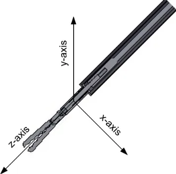
3.3 Coordinate frame associated with the instrument. . . 31
3.4 Type III full Wheatstone bridge and the corresponding placement of gauges on the inner shaft. . . 32
3.5 Type II half Wheatstone bridge and placement of the gauges measuring bending moment . . . 33
3.6 Type I quarter Wheatstone bridge and placement of the two-element rosettes mea-suring torsion and axial forces. . . 33
3.7 Examples of interchangeable tips and handles that can be attached to the instrument. 35 3.8 Placement of gauges on the middle and inner shafts . . . 36
LIST OF FIGURES xvii
3.9 Cable wiring to allow the inner shaft to slide inside the middle shaft in order to
accommodate the different tips. . . 36
3.10 Experimental setup. . . 37
3.11 Customized software interface including real-time plots and the calibration interface. 38 3.12 Instrument placement for calibration forx and y moments, axial, and torsion. . . . 40
3.13 Signal drift observed in the five measured directions. . . 43
3.14 Sample image of the instrument compressing a spring for calibration validation. . . 44
3.15 Comparison of the measured forces by a force sensor and by the strain gauges on the sensorized instrument. . . 45
4.1 Instrument close-up showing axial concentration element inside the housing. . . 49
4.2 Stress concentration diagrams as forces increase from 0 to 20 N in the axial direction. 50 4.3 Inner shaft showing the decoupling feature. . . 51
4.4 New instrument housing. . . 52
4.5 Inner housing details. . . 52
4.6 Comparison of tip design. . . 53
4.7 Quick connect mechanism. . . 53
4.8 Outer view of opening for cables and inner view of space available for cables. . . . 54
4.9 Modifications to the electronic connections of the instruments. . . 55
4.10 Calibration jig showing the instrument mounted for calibrating moments and for calibrating grasping forces. . . 56
4.11 Different tips used in the calibration evaluation. . . 58
4.12 Broken weld lines on middle shaft. . . 61
4.13 New axial element on middle shaft. . . 61
4.14 CAD model of the new middle shaft for construction in the micromachining centre. 62 4.15 Mounting of axial element on micromachining centre. . . 63
4.16 Completed middle shaft: close up of axial sensing element. . . 63
5.1 Multi-stranded medical grade cables from Cooner Wire. . . 69
5.2 Sample sterilizable connector and receptacle from Fischer. . . 70
5.3 Stainless steel bars with gauges attached. . . 72
LIST OF FIGURES xviii
5.5 Strain gauge installation process: gauges clamped for curing and instruments in oven. 78
5.6 Gauges installed and cables soldered: on inner shaft and on middle shaft. . . 79
6.1 Experimental setup used during the tissue characterization tests: tissue phantom with an embedded tumour and tissue inside training box held by plastic frame. . . 84
6.2 Data flow diagram for tissue characterization data processing. . . 85
6.3 Overlaid filtered and unfiltered position data with a second order filtfilt filter and a fourth order Butterworth filter. . . 86
6.4 Power spectrum of the position data for a novice subject. . . 87
6.5 Tactile map obtained from a systematic palpation across the entire surface, showing the stiffness factors obtained at each (x,y) coordinate in N/mm2. . . 88
6.6 Image of instrument location during identified peak. . . 88
6.7 Tactile map obtained from a localized palpation around suspected site, showing the stiffness factors obtained at each (x,y) coordinate in N/mm2. . . . 89
6.8 Data flow diagram of tissue characterization procedure. . . 91
6.9 Instruments in use during the in vivo trials. . . 95
6.10 Steps in a complex procedure composed of 5 tasks. . . 100
6.11 Cause and effect diagram for the preliminary trials. . . 100
6.12 Average task completion time for all five tasks according to the feedback provided. 105 6.13 Average mean forces with and without force feedback during the palpation task. . 108
6.14 Average mean forces with and without force feedback during the suturing task. . . 110
7.1 Task completion time for the 5 tasks according to the level of experience. . . 138
7.2 Normalized jerk as a function of experience level for all 5 tasks. . . 140
7.3 Sample graphs of force-based metrics. . . 140
7.4 Comparison of the best possible Spearman’s Rho correlations between the six levels of experience and several different metrics. . . 143
7.5 Sample graphs of force and position derivatives. . . 146
A.1 Graphical user interface for the SIMIS software. . . 177
A.2 Force graph included in the SIMIS GUI. . . 178
LIST OF FIGURES xix
A.4 Window within the SIMIS GUI to input calibration constants and adjustment
pa-rameters. . . 180
A.5 Calibration interface included in the SIMIS GUI. . . 181
A.6 Video with force overlay included in the SIMIS GUI. . . 181
A.7 Generic graphical user interface for displaying, recording and calibrating strain gauges.184
List of Tables
2.1 Experimental evaluations to assess the need for force feedback in MIST. . . 10
2.2 Locations for force sensing. . . 13
2.3 Force sensing technologies. . . 16
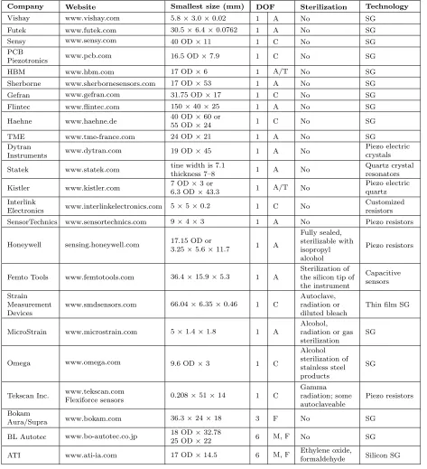
2.4 Summary of small commercially available force sensors. . . 23
2.5 Summary of force sensing instruments. . . 25
3.1 Details of the strain gauges used for force sensing. . . 35
3.2 Summary of the strain gauge calibration assessment. . . 42
3.3 Effect of gravity compensation on the bending moments: maximum error measured when moving in free space. . . 42
3.4 Maximum deviation from a theoretical zero value caused by coupling. . . 44
4.1 Summary of the strain gauge calibration assessment of the second-generation pro-totype. . . 57
4.2 Maximum deviation from a theoretical zero value caused by coupling. . . 57
4.3 The lengths of the tips used for calibration assessment. . . 58
4.4 Correction factors for torsion and grasp measurements. Calibration was completed with Tip C. . . 59
4.5 Strain gauge calibration assessment between tips of different lengths. Results show the RMS errors. . . 60
4.6 Comparison of calibration slopes on different days. . . 60
4.7 Performance assessment of axial measurements with the new sensing element. . . . 62
5.1 Relevant information of the adhesives and coatings tested. . . 71
LIST OF TABLES xxi
5.2 Working strain gauges for each combination of adhesive and coating, and their
position on the bar. . . 75
5.3 Sample results of the preliminary evaluation. . . 76
5.4 Overall performance of the best performing gauges in each combination, as
calcu-lated by adding the errors of accuracy, hysteresis, noise and drift. . . 76
5.5 Summary of results showing average performance for all gauges in each combination. 77
5.6 Results of the additional evaluation with adhesives 2 and 3. . . 77
6.1 Location of the four corners of the frame. . . 85
6.2 Results of thein vivo trials showing the range of motion used in each direction. . . 95
6.3 Results of thein vivo trials showing the range of forces applied in each direction. . 95
6.4 Plus and minus table for the 23 design and the interpretation of each test. . . . 101
6.5 Effect of force feedback on the grasping force for the five tasks. . . 106
6.6 Effect of force feedback on the Cartesian forces for the five tasks. . . 107
7.1 Detailed experience levels. . . 132
7.2 Task completion time results in seconds for all 5 tasks. . . 138
7.3 Spearman’s Rho correlations between the six levels of experience and each
position-based measure evaluated. . . 139
7.4 Comparison of the force-based metrics between novices and experts for each task. . 141
7.5 Spearman’s Rho correlations between the six levels of experience and each
force-based measure evaluated. . . 142
7.6 Scaling factors resulting from the optimization of FP Metric 1. . . 144
Nomenclature and Acronyms
Acronyms
ABS Acrylonitrile Butadiene Styrene
ANOVA ANalysis Of VAriance
API Application Programming Interface
AR Augmented Reality
AWG American Wire Gauge
CSTAR Canadian Surgical Technologies and Advanced Robotics
DOF Degree Of Freedom
EMTS ElectroMagnetic Tracking System
FF Force Feedback
FLS Fundamentals of Laparoscopic Surgery
FP Force–Position
GFF Graphical Force Feedback
GOALS Global Operative Assessment of Laparoscopic Skills
GRS Global Rating Scale
GUI Graphical User Interface
HFR High Force Ratio
HGR High Grasping force Ratio
HMM Hidden Markov Model
IAV Integral of the Acceleration Vector
ICSAD Imperial College Surgical Assessment Device
NOMENCLATURE AND ACRONYMS xxiii
ISO International Organization for Standardization
ITER In-Training Evaluation Report
LVDT Linear Variable Differential Transformer
LyE Lyapunov Exponent
MAPR Movement Arrest Period Ratio
MIS Minimally Invasive Surgery
MIST Minimally Invasive Surgery and Therapy
MISTELS McGill Inanimate System for Training and Evaluation in Laparoscopic Surgery
MMC Micromachining Centre
MRI Magnetic Resonance Imaging
OD Outer Diameter
OR Operating Room
OSATS Objective Structured Assessment of Technical Skill
PC Personal Computer
PCA Principal Component Analysis
PCI Peripheral Component Interconnect
PGY Post-Graduate Year
PVDF PolyVinyliDene Fluoride
PZT Lead Zirconate Titanate
RITA Record of In-Training Assessment
RMS Root Mean Squared
SG Strain Gauges
SIMIS Sensorized Instrument-based Minimally Invasive Surgery
SPSS Statistical Package for the Social Sciences
VFF Visual Force Feedback
NOMENCLATURE AND ACRONYMS xxiv
Variables
A Cross-sectional area
Am Amplitude
C Jerk metric
d Penetration depth
D Duration
Ea Strain caused by axial forces
Ei Strain caused by grasping forces
Et Strain caused by torsional forces
Ex Strain caused by x forces
Ey Strain caused by y forces
F Force
Fiqr Interquartile range of the Force
Fmetric Force metric
GF Gauge Factor
I Moment of Inertia
J Polar moment of inertia
k Stiffness factor
M Moment
P Path length
Pij Parameter that minimizes the coupling between the i and j directions
r Radius of the shaft
RL Lead resistance
RG Nominal gauge resistance
Saa Slope of the axial force
Sii Slope of the grasping force
Stt Slope of the torsional force
NOMENCLATURE AND ACRONYMS xxv
Syy Slope of the y force
T Torque
V Volts
VEX Excitation voltage
Vr Voltage ratio
∆V Change in voltage
z Total performance metric
zi Individual performance metric
α Scaling coefficient
λ Scaling factor
θ Rotation angle
ν transverse sensitivity ratio of the strain gauge
σ Standard deviation
σa Axial stress
σm Bending stress
τ Shearing stress
ε Strain
Units
cm centimetres
g Gram
GB GigaByte
Hz Hertz
mm millimetres
Pa Pascals
s Seconds
Chapter 1
Introduction
Minimally Invasive Surgery and Therapy (MIST) have altered the effect that surgical and
therapeu-tic procedures have on patients by significantly reducing collateral damage. In these procedures,
instruments enter the patient’s body though small incisions, or through the patient’s natural
ori-fices, in order to perform surgery or deliver therapy. This has led to improved outcomes, reduced
recovery time, reduced length of hospital stay, improved cosmesis, and reduced morbidity rates [1].
Technological advances for MIST have significantly progressed in the past 20 years (see [2]);
however, certain limitations still exist. The most limiting factor of MIST, and one that has been the
subject of significant research, is that the reduced access conditions affect the feel of interaction
forces between the instruments and the tissue being treated. The use of master–slave robotic
systems for MIST, e.g., the da Vinci® Surgical System (Intuitive Surgical, Inc.), significantly
improves instrument dexterity, accuracy and control [3]; however, the indirect nature of the system
interface causes clinicians to lose all ability to feel realistic interaction forces between surgical or
therapeutic instruments and tissue.
This loss of tactile and kinesthetic information leads to several limitations [3–6]:
• It is no longer possible to manually palpate tissue to locate certain structures or assess tissue
characteristics.
• Excessive forces can be applied, leading to increased trauma and damage to healthy tissue.
• Insufficient forces might be applied when grasping tissue or sutures leading to slippage, loss of control, and loose intracorporeal knots.
1.1 Motivation 2
Since tactile and force information is no longer available, clinicians must compensate by using
visual cues to estimate the amount of force being applied [4]. This requires a completely different
set of perceptual and motor skills, for which extensive training is required [6].
Although some procedures are successfully performed in a minimally invasive manner without
accurate force feedback or without any force information, the loss of haptic information limits the
widespread application of MIST to all fields [7]. Procedures in which dexterous fine movements
need to be performed require accurate control of both the forces applied and instrument positions
[8]. In an effort to overcome these limitations, extensive training requirements are often mandated.
1.1
Motivation
Many research studies have focused on evaluating the need for haptic feedback when performing
different tasks. Other studies have looked at the development of methods that provide force
information to the user through sensory substitution or haptic interfaces, while still others have
aimed to develop sensors that are able to measure kinesthetic or tactile information during surgery.
The latter task is complicated by the need to place the sensors as close as possible to the instrument
tip, as the measurement of forces from outside of the patient’s body is affected by interaction forces
between the instruments and the trocar at the incision point, torques from the abdominal walls or
nearby organs, internal instrument friction and mechanical advantage. This significantly constrains
the size and sterilization requirements of the sensors that may be used. Many force sensors and
sensing methods have been proposed, but none are currently available for accurate measurement
of the tool–tissue interaction forces during surgery. Several research studies have focused on
determining whether force sensing is really necessary, and if so, which degrees of freedom (DOFs)
are most important and which tasks would benefit more from the availability of force information.
In spite of these research efforts, there is still no consensus as to whether surgical procedures or
surgical training can be improved with the availability of haptic information. An in-depth study
that analyzes the need for haptic information in different applications has not yet been performed.
It is necessary to determine the types of procedures that would most benefit from force feedback,
the number of DOFs in which forces need to be sensed for different procedures, the required
resolution and accuracy with which forces need to be measured, and the effect that a lack of force
1.2 General Problem Statement 3
The search for answers to these questions is complicated by the fact that there are currently no
surgical instruments that are capable of measuring tool–tissue interaction forces. The availability
of such instruments would allow the design of experiments that might be able to address some of
the unknowns, with the ultimate goal of guiding the development of new instruments and devices.
Sensorizing instruments is not an easy or inexpensive solution, so the need for force information
has to be properly justified before committing to the addition of sensors to surgical instruments
and/or training systems. Knowledge of which tasks can be safely and effectively performed without
force feedback will simplify the development of tools and instruments for those procedures. Proper
justification could also be provided for the development of more complex instruments for those
procedures that do benefit from force information. The availability of sensorized instruments
also has an application to the development of simulators for training and skills assessment. The
force profiles obtained from real-tissue experiments could be used to develop virtual-reality based
simulators with increased levels of fidelity and realism for tasks that truly require force feedback.
Procedures that can be safely performed without force feedback, or those for which the addition
of force feedback does not improve the performance of novice trainees, can be taught using lower
fidelity simulators that focus on the development of the required skills.
1.2
General Problem Statement
In an ideal world, a surgeon would perform a surgical procedure by accessing the surgical site with
excellent visualization and direct contact with the tissue being treated, while the patient benefits
from a procedure with no side-effects and minimal invasiveness. Unfortunately, the reduced access
conditions required to minimize the invasiveness to the patient’s body affect the haptic feel of
the tool–tissue interaction. Due to the quick adoption of minimally invasive procedures into
the standard of care, there are many unknowns about the need for haptic feedback that remain
unanswered.
Nevertheless, in order to provide the best patient care, surgeons will have to continue to
deal with these limited conditions. Although it is unknown to what extent the lack of haptic
information impacts the effectiveness of the procedure, many researchers have shown that there
are clear limitations that arise from this lack of information [9, 10].
1.3 Research Objectives 4
of providing haptic information. Once these instruments become available, experiments can be
designed to establish the importance of force information and find answers concerning the
im-portance of haptic feedback. These instruments would also make an important contribution to
the development of instruments for surgical applications that are capable of measuring interaction
forces with tissue.
This work proposes to develop a set of sensorized instruments capable of measuring force
information in all degrees of freedom available during minimally invasive surgery (MIS) with the
best resolution possible, to perform a series of experiments to validate their feasibility and to
establish the importance of force information during minimally invasive surgery and training.
1.3
Research Objectives
The main goal of this thesis is to advance our understanding of the importance of force information
during minimally invasive surgery and training. To achieve this objective, the work has focused
on the following objectives:
• To design, build and test a set of instruments capable of measuring tool–tissue force
informa-tion in all degrees of freedom available during MIS and integrate it with a software platform
capable of allowing the visualization, calibration and recording of the measured data.
• To investigate solutions for the development of sterilizable sensorized elements, and to
incor-porate them into the development of a sterilizable version of the sensorized instruments.
• To investigate the usefulness of force information in surgical applications.
• To investigate the usefulness of force information for training and skills assessment.
1.4
Scope
Haptics is composed of three main categories: kinesthetic feel, tactile feel and proprioception
[11–13]. Kinesthetic information or force feedback refers to the ability to sense position, forces
and movement using muscle receptors, tendons and joints. Tactile feel deals with the sensation of
vibration, shapes and textures relying on mechanoreceptors in the skin. Proprioception deals with
1.5 Overview of the Thesis 5
when developing haptic interfaces for virtual environments. Its consideration is important when
fully representing haptic interaction between the hands and the objects in contact. A few studies
have concluded that to achieve proper haptic feedback, tactile and force sensing feedback must be
present [8, 14].
Ongoing projects at Canadian Surgical Technologies and Advanced Robotics (CSTAR) have
investigated the importance of tactile information [15,16] in surgical and therapeutical applications.
In contrast, the work presented in this thesis is focused specifically on investigating the importance
and value of kinesthetic information. Furthermore, the emphasis of this work has been on the
development of sensorized instruments and in showing their value and potential. Answers to the
questions stated above require extensive experimentation and the experiments presented herein are
intended as a starting point in the investigation of the effect that the lack of haptic information
has during MIST.
1.5
Overview of the Thesis
The structure of the rest of the thesis is as follows:
Chapter 2 Literature Review: Summarizes the state of the art in force sensing techniques for
medical interventions.
Chapter 3 SIMIS Instruments: Outlines the design and development of the first prototype of
the force sensing instruments, its limitations and preliminary evaluation.
Chapter 4 Modified SIMIS Instruments: Presents how the limitations of the original
proto-type were addressed through three subsequent iterations of the protoproto-type design,
as well as the evaluation of their performance and the lessons learned.
Chapter 5 Sterilizable SIMIS Instruments: Presents the work done towards the development
of a sterilizable version of the instruments. This includes the evaluations performed
to identify the optimal combination of adhesives and coatings for installing strain
gauges on the instruments such that they are able to withstand an autoclave cycle.
The identification of cables and connectors, as well as how the instrument can be
1.5 Overview of the Thesis 6
Chapter 6 Applications to Surgery: Explains how the instruments can be used for force
sens-ing in surgery and the development of a set of experiments aimed at determinsens-ing
the usefulness of force information when performing a surgical task. This chapter
includes insights into how the instruments could be used for tissue
characteriza-tion, and to collect data to inform the development of haptic interfaces for surgery
and simulation.
Chapter 7 Applications to Surgical Training: Describes how the instruments can be used for
skills assessment and training and the development of performance metrics based
on force information.
Chapter 8 Concluding Remarks: Highlights the contributions of this thesis and proposes
suggestions for future work.
Appendix I Software Development: Describes the development of the SIMIS software interface.
Appendix II Permissions and Approvals: Presents approval letters for copyrighted material, as
Chapter 2
Literature Review
2.1
Introduction
This chapter presents a summary of the state of the art in force sensing techniques for medical
interventions in order to identify existing limitations and future directions. Although a significant
amount of work has also been directed towards tactile sensors and haptic interfaces, the focus of this
chapter is on force sensors and sensing techniques. An extensive literature search was performed
during the period of January to July 2009 using Google Scholar and a combination of the following
keywords: force, sensor, sensing, haptics, minimally invasive, surgery and therapy. The resulting
initial list of papers and the references therein were reviewed giving priority to papers published
in the previous 15 years. A total of 126 papers were included in the compiled database. This
literature review resulted in the work presented in [9]. This initial review has been complemented
with an additional literature search performed in June 2012.
Based on the relevant information found in these papers, the remainder of this chapter is
organized as follows: Section 2.2 outlines the need for force sensing and the environmental
char-acteristics that affect force sensing in clinical applications. Section 2.3 describes the technologies
that can be used to measure force, as well as their most critical requirements when used in clinical
applications. Section 2.4 describes the technological developments to date that are commercially
available and those that are still at a developmental stage. Finally, in Section 2.5, the current
state of the art is summarized with an outline of future directions.
2.2 Force Sensing in Clinical Applications 8
2.2
Force Sensing in Clinical Applications
The desire to measure forces in MIST arises from the limitations imposed by minimally invasive
access conditions, which affect the forces that a clinician can feel with respect to tool–tissue
interactions. However, the need to measure these forces is not always obvious and becomes a
balance between cost, equipment complexity and actual benefit.
2.2.1 The Need for Force Sensing
In traditional minimally invasive surgery or therapy, a clinician holds an instrument that enters
the patient’s body through a small incision in which a trocar is placed. The trocar, abdominal
wall and other nearby tissues exert forces on the instrument that, together with the leverage
effect, cause the forces felt at the hand–tool interface to poorly represent the forces arising from
the tip–tissue interaction. Figures 2.1 and 2.2 show the conditions found in minimally invasive
procedures and robotic master–slave procedures and illustrate how force sensing comes into play.
Measurements from tool–tissue force sensors enable the force information to be provided to the
clinician in the form of graphic, auditory, vibratory, or other types of interfaces. In the case of a
master–slave system, the information can also be used to directly provide force feedback through
a haptic interface.
Since the systems represented in Figures 2.1 and 2.2 become more complex and costly with the
introduction of force sensing capabilities, the need for force sensing must be fully justified. Force
sensing information can be useful for robot control, to provide instrument–body interaction
infor-mation to reduce damage and ensure effective manipulation of the tissue, to magnify interaction
forces for enhanced sensation, or to identify tissue characteristics. This could lead to increased
safety and reduced intraoperative time, and could allow less experienced surgeons to perform more
intricate procedures with less practice.
Many procedures, however, are being performed successfully in a minimally invasive manner;
therefore, the question arises as to whether force sensing is necessary and, if so, which procedures
would benefit most from the availability of force information. Those procedures that receive no
benefit from force sensing can then be performed with simpler and more cost-effective tools, while
those procedures that do benefit from force information can be performed with increased safety
2.2 Force Sensing in Clinical Applications 9
User Tools
Display Patient
Force Sensors
Force Display
Port/ Trocar
Computer Tactile
Display Video Display
Camera Image Distorted Force Feedback
Figure 2.1: Information flow in a conventional minimally invasive procedure. The dashed lines represent the information that becomes available through force sensing.
User Interface Computer Robot/
Tools
Display Patient
Force Sensors Force
Feedback
Force Display
Port/ Trocar
Video Display
Camera Image
Figure 2.2: Information flow in a robotics-assisted minimally invasive procedure using a master– slave system. The dashed lines represent the information that becomes available through force sensing.
A number of studies have been performed to determine the need for haptic feedback (see Table
2.1 for a summary). These studies show that the benefit of force feedback is very much task, user
and system dependent. Although most results indicate that there is a need for haptic feedback in
MIS, the number of subjects is limited in each study, and there is still no consensus as to when
force sensing is necessary or beneficial [5].
Situations in which direct haptic feedback has been shown to make a difference include: (i)
per-2.2 Force Sensing in Clinical Applications 10
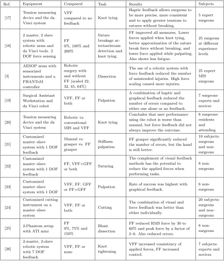
Table 2.1: Experimental evaluations to assess the need for force feedback in MIST.
Ref. Equipment Compared Task Results Subjects
[17]
Tension measuring device and the da Vinci system
VFF
compared to no feedback
Knot tying
Haptic feedback allows surgeons to be more precise, more consistent and to apply greater tensions to sutures without breaking.
5 expert surgeons
[18]
2 master, 2 slave system with robotic arms and da Vinci tools. 2 DOF force sensing
FF
0%, 100% and 200% Suture breakage ar-teriosclerosis detection and knot tying
FF improved all measures. Lower forces applied when knot tying, better approximation of the suture break force without breaking, and lower force applied while palpating. Also shows less fatigue.
25 surgeons at different experience levels
[3]
AESOP arms with sensorized instruments and a PHANToM controller
Robotic surgery with and without FF (scaled 22, 32, 45, 64%)
Dissection
The use of a robotic system with force feedback reduced the number of unintended injuries. High force scaling caused more injuries.
25 expert MIS surgeons [19] Surgical Assistant Workstation and da Vinci robot
VFF, FF or
both Palpation
A combination of haptic and graphical feedback reduced the number of errors compared to either one alone or no feedback.
7 surgeons: experts and novices
[20]
Tension measuring device and the da Vinci system
Robotic vs. conventional MIS and VFF
Knot tying
Concludes that user performance using the robot is worse than manual, but force feedback did not always improve the outcome.
6 surgeons: residents and attending [21] Customized master–slave system with 1 DOF feedback
Manual vs. grasper vs. FF grasper
Stiffness palpation
FF grasper significantly reduced the number of errors, but the hand is still better.
10 subjects: surgeons and non-surgeons [22] Customized master–slave system with 1 DOF feedback
FF, VFF+GFF
or both Suturing
The complement of visual feedback methods has the potential to reduce the applied forces when performing tasks. 8 non-surgeons [23] Customized master–slave system with 1 DOF
VFF, FF, GFF
or FF+GFF Palpation
Rate of success was highest with graphical feedback.
6 non-surgeons
[24]
Customized cutting instrument on a master–slave system
VFF, FF or
both Cutting
The combination of visual and force feedback was better than either individually.
20 subjects: surgeons and non-surgeons
[25] 2-Phantom setup with ATI mini
FF
0%, 75% and 150%
Blunt dissection
FF reduced RMS force by 30 to 60% and peak force by a factor of 2–6. Also reduced errors.
8 non-surgeons
[26]
2-master, 2-slave robotic system with 7 DOF feedback
VFF, FF or none
Knot tightening
VFF increased consistency of applied forces, FF increased control.
7 subjects: experts and novices
FF: Force Feedback
VFF: Visual Force Feedback: video display of the task site
2.2 Force Sensing in Clinical Applications 11
formance [25, 27, 28]; (ii) knot tying, where haptic feedback increases precision and consistency to
ensure the knots are tight while preventing suture breakage [17, 29, 30]; (iii) palpation, where force
sensing allows for the evaluation of tissue compliance, stiffness and viscosity [31, 32] to identify
abnormal tissue and the location of anatomical features [6]; (iv) robotic applications, where a
robot is controlled through force control to prevent tissue damage and compensate for organ
mo-tion [33] and in general master–slave systems, where force reflecmo-tion helps posimo-tion the tools and
reduce applied forces [32]; and (v) in needle-based procedures, where knowledge of the insertion
forces can improve needle placement [34]. Review papers assessing the need for haptic feedback
include [5, 35].
Other benefits of force sensing related to clinical applications include: the measurement of
applied forces for the development of new instruments and devices [36, 37]; determination of the
magnitude of forces that result in damage to different kinds of tissue, allowing for the development
of smart instruments or robots that can limit the amount of force applied to tissue [38]; tissue
modelling [7, 21, 39]; and using force profiles as an aid to skills assessment and training [40, 41].
2.2.2 Where to Sense?
A first question that might arise when the need for force sensing is identified is where to sense the
forces. To answer this question, it is necessary to consider the configuration of medical instruments
and the forces that act on these instruments. Since there are many different points of contact with
the environment, placement of the sensors must be carefully optimized [14]. A very detailed
description of the forces acting on laparoscopic instruments is presented in [11]. These include:
friction at the trocar, resistance of the abdominal wall, scaling and mirroring of the tip forces,
internal friction within the instrument and inefficiency of the mechanism itself. The forces acting
on the instrument along the access channel also need to be considered in catheter-based procedures
and those that access the surgical site through natural orifices.
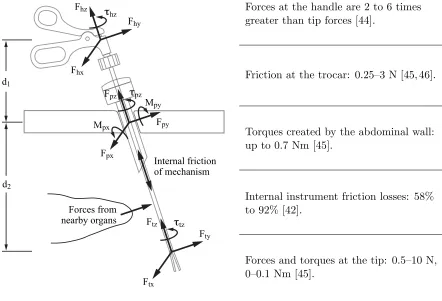
Figure 2.3 presents a diagram of the forces that may act on a surgical or therapeutic instrument
when inserted in a minimally invasive manner. Forces at the handle are what the user feels in
hand-held procedures or what the robot applies in master–slave systems. All instruments are affected
by the internal structure of the instrument and by internal instrument friction. Furthermore, it
has been shown that commercially available dissectors for minimally invasive surgery (MIS) have
2.2 Force Sensing in Clinical Applications 12
the tips of the instruments to be significantly different and nonlinearly related [43, 44]. At the
port location, the forces acting on the instrument are a combination of the friction caused by the
trocar and the moments generated by the abdominal wall when tilting the instrument [45, 46].
Other forces could be generated by nearby organs acting on the instrument shaft. These latter
forces are significant in procedures that use flexible instruments, such as natural orifice procedures,
single-port access procedures or catheter-based therapies.
Mpx τpz
Fpx
Mpy
Fpy
Fpz τhz
Fhx
Fhy
Fhz
τtz
Ftx
Fty
Ftz
Internal friction of mechanism d1
d2
Forces from nearby organs
Forces at the handle are 2 to 6 times greater than tip forces [44].
Friction at the trocar: 0.25–3 N [45, 46].
Torques created by the abdominal wall: up to 0.7 Nm [45].
Internal instrument friction losses: 58% to 92% [42].
Forces and torques at the tip: 0.5–10 N, 0–0.1 Nm [45].
Figure 2.3: Forces acting on minimally invasive instruments.
Table 2.2 presents a summary of the different places where forces can be sensed [4]. Depending
on the need for force sensing, it might be necessary to measure the hand–tool interaction forces,
(for example, to determine the forces required to insert needles, for the development of training
simulators or to determine the requirements of surgical robotic systems), or the forces applied by a
robotic system on the tool (for example, for force feedback control [47]). Measuring the tool–tissue
2.2 Force Sensing in Clinical Applications 13
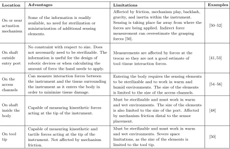
Table 2.2: Locations for force sensing.
Location Advantages Limitations Examples
On or near actuation mechanism
Some of the information is readily available, no need for sterilization or miniaturization of additional sensing elements.
Affected by friction, mechanism play, backlash, gravity, and inertia within the instrument. Sensing is taking place far away from where the forces are being applied. Indirect force
measurement can overestimate the grasping forces [50].
[50–52]
On shaft outside entry port
No constraint with respect to size. Does not necessarily need to be sterilizable. The information is useful for the design of robotic devices or when calculating the amount of force the hand needs to apply.
Measurements are affected by forces at the trocar so they are not a good estimate of tool–tissue interaction forces.
[41, 53]
On the access channels
Can measure interaction forces between the instrument and the tissue surrounding the instrument as it enters the body in order to minimize tissue damage.
Entering the body requires the sensing elements to be sterilizable and to work in warm and humid environments. The size of the elements is limited to the size of the access channels.
[54–56]
On shaft inside the body
Capable of measuring kinesthetic forces acting at the tip of the instrument.
Must be sterilizable and must work in warm and wet environments. The size of the elements is also limited to the size of the port. Affected by mechanism friction distal to the sensor placement.
[48]
On tool tip
Capable of measuring kinesthetic and tactile forces acting at the tip of the instrument. Not affected by mechanism friction.
Must be sterilizable and must work in warm and wet environments. Severe space limitations, as the size of the elements is limited to the tool tip.
[50]
minimize damage to the abdominal wall when twisting the instrument to reach difficult areas, or to
minimize damage when inserting flexible instruments through vessels or through natural orifices.
In most applications, the goal is to obtain the tip–tissue interaction forces in order to assess tissue
trauma or provide feedback during surgery.
The measurement of forces is simplified by placing the sensors outside of the body, since size and
sterilization constraints are not involved. However, using this information to estimate forces acting
at the instrument tip is inaccurate. The effect of friction at the trocar, abdominal wall forces, and
the leverage effect make it such that tool–tissue interaction forces can only be accurately sensed
by placing the sensors as close as possible to the instrument tip [48, 49]. The forces at the tip are
sometimes so delicate that other forces acting on the instruments can easily mask them [35].
Owing to the difficulties inherent in placing sensors inside the body, researchers have been
trying to address the discrepancy between handle and tip forces. The design of a mechanically
efficient instrument for sensing grip forces at the handle is presented in [57]. This instrument uses
2.2 Force Sensing in Clinical Applications 14
show a significant improvement in the ability to detect grip forces based on handle forces (stiffness
of tissue and arterial pulse). To address the frictional forces introduced at the trocar, it was shown
in [46] that friction within a trocar could be significantly reduced with a proper design of the sealing
mechanism or by using lubricants. Finally, [58] developed a model for friction compensation, in
their case using the da Vinci instruments. They show that a “friction compensator with multiple
single-state elastic friction models” is reasonably effective at cancelling the Coulomb friction of
the joints of the slave manipulator in unidirectional motion. These solutions, however, do not deal
with the effect of the abdominal wall on the instrument, or the scaling that occurs due to the
fulcrum location on the instrument.
Sensing for needle-based procedures presents unique challenges. It has been shown that knowing
the forces that act on the needle during insertion can lead to improved placement precision [34].
Due to the small size of the needles, placement of sensors anywhere within the needle shaft is
extremely difficult and most systems measure the forces outside of the body [59]; however, novel
sensor designs have been capable of estimating needle tip force and sidewall friction in 7 DOFs
[60, 61].
2.2.3 What to Sense?
Another consideration when dealing with force sensing in MIST is to identify which forces need
to be measured. Full representation of the instrument interaction can only be achieved by
simul-taneously measuring three orthogonal forces, three orthogonal moments, and the actuation force
(grip or cut depending on the instrument). For telemanipulators to be completely transparent,
sensing and display of all 7 DOFs of haptic information are needed [14], in addition to tactile
information [62]. Furthermore, asymmetry between the number of DOFs in force sensing and the
number of DOFs in a haptic device can affect stability in bilateral teleoperation.
For some applications and tasks, however, sensing forces in some of the degrees of freedom
might be sufficient to achieve the desired results. Identification of which degrees of freedom need
to be sensed for particular tasks still remains an open area of research. Considerations include the
differences arising from the use of different instruments and instrument configurations, the task
being performed, the level of expertise of the subjects, and the type of procedure.
Some limited studies have tried to identify the benefit of measuring forces in different directions.
2.3 Force Sensing 15
that feeding back forces in just two degrees of freedom for certain tasks is a significant improvement
over no force feedback, while adding the axial direction does not make a significant difference in
terms of applied forces. Another study, presented in [62], concludes that grip forces and Cartesian
forces are decoupled; in other words, providing feedback in translational forces does not help with
grip force control and vice versa.
2.3
Force Sensing
After assessing the need to sense forces and the characteristics of the environment that affect force
sensing in clinical applications, consideration must be given to determine which type of sensor can
best meet the design constraints. This section outlines existing technologies for force sensing and
how these different technologies can be applied to achieve sensing in multiple degrees of freedom.
2.3.1 Technologies
The most commonly used technologies for sensing forces are strain gauges, piezoelectric sensors,
capacitive-based sensors, and optical sensors. These technologies and other more novel methods
are summarized in Table 2.3 and discussed below.
Strain gauges: The most common technology employed for force sensing uses thin metal
foils applied to the surface of an instrument to measure the deformation caused by the applied
force. These foils, when attached to a thin plastic backing material and oriented in a particular
arrangement, are called strain gauges [64]. Strain gauges have been successfully used in instruments
for medical applications [23, 36, 65, 66] (more details on these instruments are provided in Section
2.4.2). Figure 2.4 shows examples of strain gauges applied to MIST instruments.
To achieve multi-axis measurements using strain gauges, special structural elements are
com-monly used on which strain gauges are placed at different locations to allow the different forces and
moments to be measured. A review of force sensing structures found in the literature is presented
in [67]. The Stewart Platform [68], the Maltese Cross [69], and Junyich’s configuration [70, 71]
and their variations are the most commonly used structures. Other novel structures for multi-axis
sensing are presented in [67, 72–74]. The selection of one of these structures for force sensing
purposes depends on the desired balance between signal noise levels, measurement isotropy, signal
2.3 Force Sensing 16
Table 2.3: Force sensing technologies.
Technology Advantages Limitations
Strain gauges
Small size and can be sealed in a waterproof environment. Multi-axis measurement is easily achieved.
Sensitive to electromagnetic noise and temperature changes leading to drift and hysteresis. Tradeoff between the sensitivity of the measurement and the stiffness of the structure [4].
Optical sensors
Forces can be measured in as many as 6 DOFs [75]. They can be used inside Magnetic Resonance Imaging (MRI) scanners [76]. Also, they can detect changes with high sensitivity and reproducibility with no hysteresis [75].
Limitations include sensitivity to noise, and that optical fibres cannot typically achieve small bending radii [4].
Measurement of actuator input
The system is no longer limited by the sensor bandwidth (which can make a control or feedback system unstable), and it is not necessary to incur the cost of force sensors [77]. Does not rely on force sensors, which often do not operate properly when exposed to high temperatures and humidity [78].
Very sensitive to uncertainties [78]; if the system cannot be properly modelled (due to high joint friction, for example), the estimation error can be significant.
Capacitive-based sensing
Limited hysteresis, better stability and increased sensitivity compared to strain gauges [4, 79].
Require more complex signal processing and are more expensive than other methods [4, 79].
Resonance-based sensing
High signal to noise ratio and digital processing is
possible. Affected by nonlinearities and hysteresis [79].
Piezoelectric sensing
Since these materials generate their own voltage, no additional power supply is needed [4]. They have high bandwidth, high output force, compact size and high power density [79].
Very temperature dependent and subject to charge leakages [4]). This results in a drifting signal when static forces are applied, thus making them suitable for the measurement of dynamic loads only.
(a) (b)
2.3 Force Sensing 17
Optical sensors: Another technology often used for sensing force is based on measuring the
change in intensity or phase of a light signal as it passes through a flexible structure. When forces
are applied to the structure, the way in which the structure flexes creates a change in the intensity
of the light or causes the phase of the light signal to vary proportionally, making it possible to
estimate the amount of force or pressure being applied. The design of 6-DOF optical force sensors is
presented in [75,76], while the development of optical force sensors for MIST is discussed in [81,82].
Measurement of actuator input: When actuators are used to drive the joints of a
manipu-lator, the input to the motor (for example, the current drawn by electrical motors or the variation
in the pneumatic pressure in pneumatic actuators), can be directly related to the amount of force
or torque generated. Since these signals are affected by internal joint friction and actuator
nonlin-earities [4], knowledge of the mechanism kinematics and friction dynamics is critical for force and
torque measurements to be accurate. Measurement of actuator input is mostly used in master–slave
(teleoperation) systems for force or torque control or for haptic feedback.
In order to use the input to the actuators as a means of estimating applied forces, an
observer-based control system is commonly used. For this purpose, a model of the system needs to be
developed and the uncertainties of the model compensated for or measured. Observer-based sensing
compares the difference between the output of the nominal model and the actual system output. If
the uncertainties are known, the disturbance observer can estimate the amount of force generated at
the output based on the actuator input [83]. To measure uncertainties, [84] uses neural networks
to estimate friction, inertia, and gravity, while [78] uses a modified extended Kalman filter to
compensate for the modelling error, sensing bias and measurement noise. A Nicosia state observer
is utilized in [85] together with a general bilateral control law that ensures matching of the forces
at the master and the slave. Examples of these types of controllers are presented in [77, 78, 83, 84],
while only the latter has actually been used in MIST.
Capacitive-based sensing: This type of sensing is commonly used to measure tactile
infor-mation. It depends on the use of a membrane, which when deflected, causes the distance between
two electrodes separated by a dielectric material to change. Examples of instruments based on
this concept include [86, 87].
Resonance-based sensing: This type of sensing is also membrane based. A change of force
and pressure can be detected by measuring the change in the resonant frequency of the membrane.
![Figure 2.4: Examples of strain gauges used in instruments to measure forces during natural orificeprocedures [37] (left) and during laparoscopic procedures [80](right).](https://thumb-us.123doks.com/thumbv2/123dok_us/7752091.1271029/42.612.77.546.163.547/figure-examples-instruments-measure-natural-oriceprocedures-laparoscopic-procedures.webp)