Available Online atwww.ijcsmc.com
International Journal of Computer Science and Mobile Computing
A Monthly Journal of Computer Science and Information Technology
ISSN 2320–088X
IJCSMC, Vol. 4, Issue. 5, May 2015, pg.23 – 28
RESEARCH ARTICLE
Earliest Detection of Cluster Head Failure in
Wireless Sensor Networks
Satish Ajur
Computer Networks and Engineering, New Horizon College of Engineering, Bangalore 560087, India
Mrs.Uma N
Asst. Professor, Dept of Computer Science and Engineering, New Horizon College of Engineering, Bangalore 560087, India
Abstract— This paper considers detection of cluster head failure problem in WSNs and resolved in proposed system by efficient detection of cluster head failure mechanism to identify the head failure more with accuracy. Cluster head broadcasts a ―heartbeat‖ messages to its members and each cluster members identifies independently received ―heartbeat‖ message. Further-more to identify cluster head failure with more accuracy co-operative detection of cluster head failure with neighbor nodes.co-operative detection confirms head failure at earliest by checking members status information at each member through independent and co-operative detection mechanisms. Simulation results shows that failure detection probability and efficient detection of head failure performance in terms of the failure detection and the detection time and in turn shows energy efficiency plots.
Keywords— cluster;CH- cluster-head; TDMA; failure detection; wireless sensor network
I. INTRODUCTION
II. NETWORK DISGN
This section defines the network design considered in this paper and demonstrates the proposed method.
A. Network architecture
Here we assuming that one sink node which is center of communication in network with cluster members in the network through their cluster head. Figure 1 shows the architecture of the network and nodes are distributed uniformly in the region interest. All sensor nodes are homogeneous and have same energy and assuming that clusters are single hop clusters and in-cluster communication is through the TDMA scheme at the MAC layer. Each frame has defined time slots and are communicating within the defined time slots and also detects the status the cluster head within the same. Since it is using timeslots initial timeslot is reserved for cluster head to broadcast “heartbeat” message.
B. Frame structure
C. Status Bit
Status bit is Boolean value to represent the head status and this bit is broadcast with the heartbeat message with setting SB=1 initially at TS0 timeslot. Each cluster member maintains the status information of CH.
SB=1 indicates head is alive SB=0 indicates head failed.
D. Neighbor list
Along with the status bit information members need to maintain neighbor nodes which one-hop-neighbors and neighboring information maintained by overhearing neighbors confirmation messages sent to its neighbors.
E. Detection methods
The head failure detection process is sub divided into two methods: independent detection and co-operative detection.
1) Independent detection
Consider cluster head broadcasts “heartbeat” message in its TS0 time slot to its members. Cluster members independently detects status bit information if SB=1 head is alive else head failed. But due to physical damage or signal interference chances false of failure detection hence for cross confirmation member overhear the neighbor status bit information for better accuracy detection.
2) Co-operative detection
After independent detection if any node detects head failure to confirm head failure it has to piggyback the neighbor status bit information in its own timeslot by means of an overhear technique.
In this stage, if cluster member need to follow different case study depending on independent detection results in its own timeslot with its neighbors.
Case.1)
If SB=1, transmit data to CH in its timeslot and remain asleep to save energy in other timeslots. Case.2)
If SB=0, demonstrates cluster head failed. In this case
Member overhears neighbor‟s status information with its one-hop-neighbors in its timeslot. Overhear when SB=0, members may have following approaches:
If member overheard data packet with SB=1 from its one of its neighbors, stop overhearing, set SB=1 and transmit data in its time slot.
slot else sleep
Step-3.2.3If neighbor node has alive status bit and current node has failure then validate with other neighbor node in its slot and repeat step-3.2.1
Step-4 Data transmission using TDMA method to every cluster head along with Status bit value
Step-5 Simulate the results
III. ANALYTICAL MODEL In this section we are analyzing the performance of the proposed mechanism.
I. False probability detection
Say pi indicates falsely detected failed by its member. Hence pi can be written as Pi=1-Pi`
Where Pi` is correct head detection and 1-Pi gives failed false head failure detection. By the above formula we have,
Pi=p-p.(1-p).(1-pni) –p2.(1-p).(1-pni-1)+(1-p)2.pni+1.(ni-1)
IV. SIMULATION RESULTS
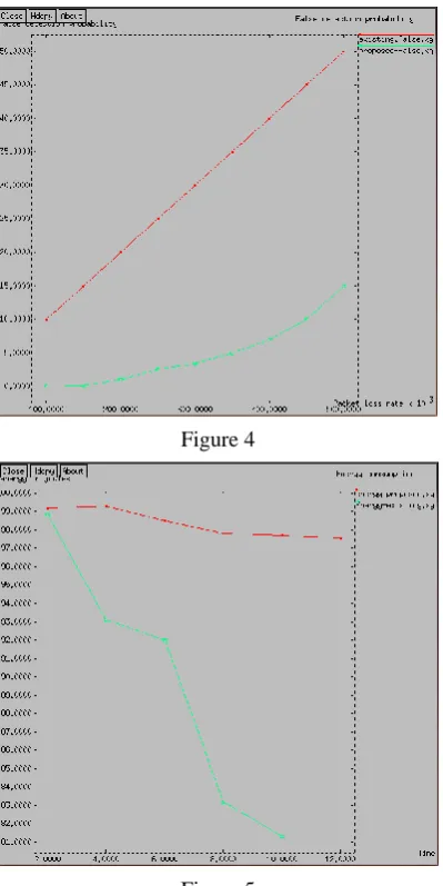
In this section, we verify the efficiency of proposed method and evaluation of proposed method through the simulation results. The simulation results are performed on NS2.It is observed that simulation results are very near to theoretical results. It is observable point that as packet loss rate simulation result also increases. It notable point that as number of nodes increase packet loss rate and detection rate also decreases. Figure 5 compares the energy plot shows the more efficient energy conservation in ach node level.
Figure 4
Figure 5
Detection time with proposed method keeps constant at one frame time whereas in tradition system decreases as packet loss rate increases. Consider figure 3 throughput graphs show efficiency of proposed system over existing system. Energy plot demonstrates the energy conservation using proposed method. Figure 4 shows Probability of failure detection and Figure 6 packet loss rate graphs shows comparison between existing and proposed methods.