Optimizing Time and Space MIMO Antenna System
for Frequency Selective Fading Channels
Kai-Kit Wong, Student Member, IEEE, Ross D. Murch, Senior Member, IEEE, and
Khaled Ben Letaief, Senior Member, IEEE
Abstract—Smart or adaptive antennas promise to provide significant increases in system capacity and performance in wireless communication systems. In this paper, we investigate the use of adaptive antennas at the base and mobile stations, operating jointly, to maximize the average signal-to-interference and noise ratio (SINR) of each packet in the system for frequency selective channels with prior knowledge of the channel at the transmitter. Our approach is based on deriving an analytic formula for the average packet SINR and using the Lagrange multiplier method to determine an optimum. We derive necessary conditions for an optimum solution and propose an analytical expression for the optimum. Our analytical expression is not guaranteed to be the global optimum but it does satisfy the derived necessary conditions and, in addition for frequency flat channels, our results reduce to expressions for optimal weights previously published. To demonstrate the potential of the proposed system, we provide Monte Carlo simulation results of the system bit-error rates and make comparisons with other adaptive antenna systems. These show that significant improvements in performance are possible in a wireless communications context.
Index Terms—Co-channel interference, flat and frequency selec-tive fading channels, intersymbol interference, MIMO, smart an-tennas, wireless communication systems.
I. INTRODUCTION
F
UTURE WIRELESS COMMUNICATION systems areexpected to support a wide range of services that will require high transmission rates of several megabits per second. Communicating at these high transmission rates over wireless channels with a limited spectrum implies that an increase in the capacity of current wireless systems will need to be achieved [1]–[4].
One possible approach to increase system capacity is through the use of smart or adaptive antennas. Several smart antenna systems have been proposed, and demonstrated at the base sta-tion (BS) of the wireless communicasta-tion system, and these have shown that significant increases in capacity are possible [5]–[8]. Further increases in capacity may be possible by including smart antennas at the mobile station (MS) in both the down and uplinks as well. Although this may not be practical for current mobile
Manuscript received December 1, 1998; revised February 5, 2000. This work was supported in part by the Hong Kong Research Grant Council under Grant CRC96/99.EG01 and by the Hong Kong Telecom Institute of Information Tech-nology.
The authors are with the Center for Wireless Information Technology, De-partment of Electrical & Electronic Engineering. The Hong Kong University of Science & Technology, Clear Water Bay, Kowloon, Hong Kong (e-mail: [email protected]; [email protected]; [email protected]).
Publisher Item Identifier S 0733-8716(01)04999-X.
stations, reductions in antenna sizes and also the use of note-book computers in wireless computing applications may make this feasible in the future [9]. Therefore, it is worthwhile inves-tigating the use of smart antennas at the MSs and BSs operating jointly and determine whether the increased performance jus-tifies the increased system complexity. We refer to this type of system as a smart base and smart mobile (SBM) antenna system. Recently, systems similar to SBM have been considered by several authors and they have utilized space time coding in mul-tiple-input multiple-output (MIMO) channels [10], [11] or joint transmitter receiver systems [12]–[19]. In [10], Foschini pro-posed the combined array processing and symbol cancellation approach for obtaining high capacity in MIMO antenna system while Raleigh and Cioffi [11] studied space–time water-filling for multipath fading, with prior knowledge of the channel at the transmitter. In [12]–[14], the capacity of the system is maxi-mized under flat fading channel conditions without co-channel interference (CCI). In [15], the signal-to-noise ratio (SNR) is maximized by using a joint multiple transmission and reception filter system. However, an equalizer is required to mitigate the effect of intersymbol interference (ISI) and CCI is not consid-ered. Results on joint transmitter and receiver optimization ap-peared in [16] and [17], and are based on a frequency domain analysis. In [18] and [19], smart antennas at the BS and MS which jointly maximize signal-to-interference and noise ratio (SINR) for flat Rayleigh fading channels in the presence of CCI are studied. In addition, [20] and [21] provide interesting results for joint optimization for the case of additive white Gaussian noise (AWGN) and where antenna arrays at the transmitter and receiver are utilized. However overall, the optimization problem (in the sense of maximizing the SINR) for frequency selective fading channels has not been considered.
In this paper and in contrast to the previous work, a solution to the broader problem of performance optimization for multi-path frequency selective fading channels in the presence of in-terference is provided using a discrete time channel model. We consider smart antennas jointly at the BS and MS to suppress ISI together with CCI. The paper provides a useful extension of [12]–[20].
Our approach is based on deriving an analytic expression for the average SINR of each packet with the constraint of fixed transmitter power. The Lagrange multiplier method is then uti-lized for finding an optimal solution. Several solutions are found which satisfy the Lagrange conditions for a maximum and we select the optimum of these to form an analytic solution. Al-though this solution is not guaranteed to be the global optimum, it reduces to the global optimum for flat fading channels and performs better [in terms of average bit-error rate (BER)] than
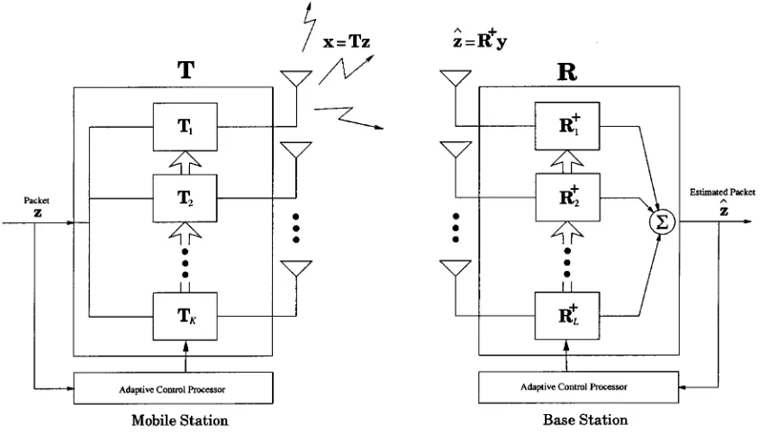
Fig. 1. System configuration demonstrating the uplink in which smart antennas are included at both BS and MS in the down and uplinks.
other techniques in numerical simulations for frequency selec-tive fading channels. It is also shown that under the assumption of orthogonal transmit weights, the solution is the optimum in the sense of maximizing average SINR. Throughout, we utilize quaternary phase-shift keying (QPSK) modulation in an envi-ronment with ISI, AWGN, and CCI in a similar way to that de-scribed in [22].
This paper is organized as follows. In Section II, we intro-duce some necessary notation that is used throughout the paper. Section III derives analytical expressions for the optimal an-tenna weights for SBM in frequency selective and nonselective fading environments with CCI. Section IV presents simulation setup and results and we have some discussion in Section V con-cerning practical issues. Finally, we make some concluding re-marks in Section VI.
II. SYSTEMMODEL
The configuration of the SBM system is shown in Fig. 1 where antennas are located at the MS and antennas are lo-cated at the BS. A time division multiple access (TDMA)-based transmission system is assumed and data is transmitted in blocks of symbols of length and the number of spatial subchannels (symbols or spatial dimensions) per sample is denoted by .
Therefore, the total number of symbols sent per packet is and this is written in packet form as
where the superscript denotes the transpose operation. The input vector is assumed to have independent identically dis-tributed components. The packet is multiplied by a trans-mission matrix
.. . ..
. . ..
(1)
to produce a packet which is transmitted by the th antenna.
At the BS, antennas are used for reception and the channel between the th BS antenna and th MS antenna is assumed quasistationary and can be considered as time-invariant over a packet, so that it can be characterized by a Toeplitz matrix
..
. . .. . .. . .. ...
. ..
. .. . ..
..
. . ..
..
. . .. . .. ...
(2)
where the received packet is given by .
The maximum delay is assumed to last for samples and the discrete-time channel gains are defined by an -ray model and this is discussed in the simulations in Section IV.
Following Fig. 1, the received packet is then weighted in space and time by a matrix where
.. . ..
. . ..
(3)
from all antennas as and the received
data by all antennas as , we can write
the entire MIMO system as
(4)
where is the noise vector and is
assumed to be AWGN with power . Likewise, is given by
..
. . .. ...
(5)
where is defined in (2). The overall system can, therefore, be written as
(6)
where and
.
Interference is also considered and interferers are assumed. For now, we consider the uplink only. However, the formulation for the downlink will be similar, but with generally different CCI. The interfering channel matrix from the th interferer is defined similar to (5), and the transmitted signal vector from the th interferer is also defined similar to . The signal vectors are assumed to be uncorrelated with themselves and . In addition, the receiver employs perfect timing and the interfering signals are time-aligned with the desired signal. As a result, is then given by
(7)
where and are elements of
, and which contains all the off
diagonal elements. Hence, in (7), the first term represents the desired signal, the second term represents the ISI of the desired signal, and the third term is the CCI and noise.
III. OPTIMALSBM SOLUTION
Using the system model described in Section II, our objec-tive is to find the mobile (transmit) and base (receive) matrices that maximize the average SINR of the packet with the constraint of a fixed transmit power (the norm of each column vector of is ). We note that both and are arbi-trary and do not necessarily have orthogonal columns (or equiv-alently, are not necessarily unitary when ). By al-lowing solution weights with nonorthogonal columns, we allow the possibility of improved performance under a wider range of conditions than would otherwise occur with weights with or-thogonal columns.
Our overall objective can then be written as
(8)
where is the th column vector of and the average SINR of the packet is defined as
(9)
where is the th symbol SINR, is the th column vector of and
(10)
To find the receive weight matrix that maximizes (9), we first rewrite the SINR expression as
(11)
where
(12)
It is known [18] that the that maximizes (11) is
(13)
where is arbitrary and does not affect the SINR. Hence, to simplify our equations, we set for all . Substituting (13) into (11), the SINR can be expressed as
(14)
We now wish to maximize (14) subject to the power
con-straint . To make the analysis more succinct,
we write where is an
arbi-trary matrix and is the matrix that contains all the
eigenvectors of so that , where
. Based on the power constraint, it can be shown easily that must satisfy
To find the weights which maximize (14), subject to the con-straint (15), we use the Lagrange multiplier method. Specifically
(16)
where represents the Lagrange multipliers. Now, consider the derivative of with respect to the real and imaginary parts of
for any . We write this in a compact notation as
(17)
and as a consequence, we have
(18)
The optimum must satisfy . Since the
expres-sion involves the gradients of inverse matrices, this is a non-trivial exercise and we rewrite the expression by defining the following matrices
(19)
with . Then using (53) in the Appendix recursively, we can write
(20)
As a result, (18) can be expressed as
(21)
After setting , we have the system of simultaneous nonlinear equations
(22)
The above equations do not allow an analytic solution to be found. However, it can be shown (see the Appendix) that the terms under the summation are eliminated by setting
(23)
then (22) becomes
(24)
The imposed condition (23) is desirable and it will be shown later that under the assumption of unitary (or orthogonal) transmit weights, our solution is the global optimal in the sense of maximizing average SINR.
To solve (24), we first note that the diagonal matrix has nonzero eigenvalues of which none are repetitive (since in gen-eral is random and unlikely to have repetitive eigen-values). By also realizing that from (15), the
solu-tion for is
if
if (25)
for a given , and .
As a result, the transmit weight matrix is
(26)
where is a matrix that contains the eigenvectors that corre-spond to distinct eigenvalues of . In addition, the corresponding receive weight matrix is
(27)
where we have used (23). Using these weights, the overall SINR is
(28)
and the overall maximum SINR is achieved by selecting the eigenvectors corresponding to the largest eigenvalues as the transmit weight matrix in (26).
The expressions (26) and (27) provide analytical expressions for the joint antenna weights at BS and MS. The combined effect of transmit and receive antenna weights is to perform space-time equalization and CCI suppression jointly at the BS and MS. In order to utilize them, we must know the channel and also the interference . The practicality of this and its computational load are discussed in Section V-A.
interference does not play a dominant role in maximizing the overall SINR, and high noise conditions prevail. In this situa-tion, improved SINR performance occurs if the weights com-bine the signals together to improve noise performance but at the expense of allowing some additional interference. Such trade-offs can only occur if the weights are allowed to have nonorthog-onal columns and further work needs to be performed to find the optimum solution in this situation.
We conclude this section by pointing out that if we begin with the assumption that has orthogonal columns, then by using the inequality (50) on (14), we obtain an upper bound
(29)
where denotes the summation of the largest eigen-values of the input matrix. Since trace is invariant by orthogonal transformation, we have
(30)
and now the upper bound is the same as the SINR (28) ob-tained by the SBM solution. Therefore, under the assumption of transmit weights with orthogonal columns (or equivalently unitary transmit weights when ), the SBM solution is optimal in the sense of maximizing SINR.
A. Flat Fading
It is interesting to determine the form of (26) and (27) for flat fading and compare with those in [12]–[19]. In a flat fading radio environment, the mobile radio channel has a constant gain and linear phase response over a bandwidth that is greater than the bandwidth of the transmitted signal and, therefore, ISI is negligible. Hence, only in (2) is significant and the re-ceived signal can be written as (7), but with
(31)
where the identity matrix has dimensions . Consequently, the matrix can be expressed as
..
. . ..
(32)
where the elements are the corresponding elements of in which
..
. . ..
(33)
and similarly can be defined by
(34)
where and are defined similarly to (31).
It follows [23] that there are only distinct eigenvalues of , each with multiplicity and that these are the same as the eigenvalues of . Therefore, utilizing the results derived in (26) and (27), the weight matrices, and , which
maximize the output SINR are given by ,
and , respectively, where
(35)
and
(36)
and is the eigenvector that corresponds to the largest
eigen-value of .
This solution is the same as the results in [12]–[19]. The corresponding maximum SINR can be found very easily to be per symbol, where is the largest eigenvalue or maximal eigenvalue of the matrix . Therefore, the maximum SINR we can achieve with the constraint is when the weight vectors (35) and (36) are used throughout the packet.
For the special case of flat fading without interference, is simply the correlation matrix of the complex Gaussian noise. Hence, the optimum values of and the corresponding maximum SINR are then, respectively, given by
Maximum eigenvector of (37)
(38)
(39)
This can be considered as an extension of maximum ratio
com-bining (MRC) with multiple antennas at BS and MS. In
partic-ular, the BS transmits according to the channel condition and the MS combines the received signals based on their SNRs. When there is only one transmit antenna, (38) and (39) reduce to the standard MRC formulas.
IV. SIMULATIONRESULTS
when we use a conventional adaptive antenna system with two antennas at the BS, we refer to it as 2 1 conventional.
Average bit-error probability is provided for various CCI [Signal-to-interference ratio (SIR)] and AWGN (SNR). The “average SNR per branch-to-branch” in the -axis of the
figures is defined as where is the average
channel power from a transmit antenna to a receive antenna, is the average bit energy, and is the noise spectral density. For each simulation, data packets consisting of 50 data symbols are transmitted with more than 10 000 independent channels [22].
The simulation is performed in the context of a QPSK sig-naling scheme, the transmitted baseband signal is
(40)
where is the complex symbol sequence having the values of and is the pulse shaping function at the trans-mitter which gives a bandlimited transmitting signal. One pop-ular example of is the root-raised cosine pulse shaping filter and here we take roll-off factor of 0.3. In practice, pulse shaping is performed at both the transmitter and receiver to pro-vide matched filtering for SNR enhancement.
A. Channel Model
The antenna elements transmit or receive information through a wireless communication channel which is here characterized by a multipath fading model. For a particular channel, the multi-path model is represented by its channel impulse response using a -ray model defined as [24], [25]
(41)
where the subscripts refer to the channel between the th and th antenna at the BS and MS, respectively and is the total number of paths. Likewise, and are, respectively, the complex gain and time delay for the th path of the diversity channel. In the simulation, the channel of each link contains ten random multipath components [ will be defined later in (41)] and one interferer .
To determine , we can use either ray tracing (deterministic model) [26] or statistical approaches. In this paper, a statistical approach is used to allow easier control of channel parameters such as delay spread. Assuming that paths with different delays are uncorrelated (i.e., uncorrelated scattering) and that the paths are uncorrelated for each antenna branch so as to provide per-fect spatial diversity. As a result, path gains and
are uncorrelated if or or . This will be
realistic if antenna spacings at the MS and BS are, respectively, greater than 0.4 and 20–40 wavelengths. We can refer to [27] for the effect of correlation on the antennas. Additionally, the trans-mitted signals from other users causing CCI are also assumed to suffer from the delay spread of radio channels with uncorrelated path gains. We model statistically by zero-mean, complex
Gaussian random variables, with their power following the ex-ponential delay profile given by
for
elsewhere (42)
Hence, in (2) is equal to where
denotes the convolution operator between two continuous time signals. For simplicity, we consider only the paths with delays less than five normalized rms delay spread which is defined as where and are the rms delay spread and symbol period, respectively. In addition, we specifically assume
the path delay as .
B. Results
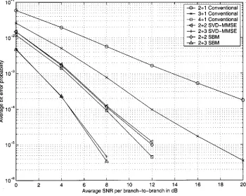
In Fig. 2, results are provided for a flat Rayleigh fading channel in the absence of interference for the configurations 2 1 conventional, 3 1 conventional, 4 1 Conventional, 2 2 SVD-MMSE, 2 3 SVD-MMSE, 2 2 SBM, and 2 3 SBM. A close observation of this figure indicates that there is over 100 times decrease in when 2 2 SBM is employed compared to 2 1 conventional for dB. This is an interesting result and reveals that significant advantages can be achieved by using smart antennas at both the BS and MS. In addition, SVD-MMSE has almost the same performance as that of SBM, which agrees with theoretical results.
It can also be argued that to obtain fair comparisons, the same number of antenna elements should be utilized in both config-urations. Taking four antenna elements, this implies that we should compare 2 2 SBM and 3 1 conventional and refer-ring to Fig. 2, this reveals that 2 2 SBM has about tenfold
im-provement in BER for dB. This advantage in SBM
comes about by realizing that an additional branch of diversity is available compared to the conventional system even if the total number of antennas used in both configurations is the same. Note also that more than tenfold improvement is possible for the 2 3 SBM system compared with 4 1 conventional system
when dB.
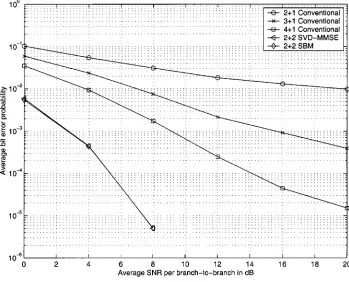
In Fig. 3, results are provided for a flat Rayleigh fading channel but with CCI at dB. These results demon-strate that 2 2 SBM provides over 100 fold decrease in
as compared to 2 1 conventional when dB. The
results also illustrate that more than a tenfold reduction in is possible for 2 2 SBM compared with 3 1 conventional
for dB. Note that the results for SVD-MMSE now
become slightly worse compared to SBM, and the difference is supposed to get larger as SNR increases.
Fig. 2. Average error probability performance of SBM under conditions of no CCI and flat fading.
Fig. 3. Average error probability performance of SBM under conditions in flat fading channels with a single dominant CCI atSIR = 15 dB.
that of 3 1 conventional when dB. Note also that 2 2 SBM and 3 1 conventional smart antenna system can have better performance compared with 2 3 SVD-MMSE, starting at dB, and dB, respectively.
In Figs. 5–7, results for frequency selective fading channels are presented. The frequency selective channels
are characterized by the normalized rms delay spread, , which is an important and convenient measure of the degree of frequency selective fading. In particular, in digital transmission over multipath channels, the BER is highly de-pendent on [28]. In our simulations, we will exclusively
Fig. 4. Average error probability performance of SBM under conditions in flat fading channels with a single dominant CCI atSIR = 0 dB.
Fig. 5. Average error probability performance of SBM in frequency selective fading channels(D = 0:5) with no CCI.
In Fig. 5, results of BER are provided for with no CCI. Here it is revealed that 2 2 SBM and 2 2 SVD-MMSE have over 100 fold improved BER performance for
dB when compared even to 4+1 conventional. This huge perfor-mance improvement can be explained by realizing that for SBM system, CCI suppression, and equalization can be performed
jointly while the conventional smart antenna systems are unable to equalize the signal effectively. Additionally, in the absence of CCI, SVD-MMSE has the same performance as SBM.
Fig. 6. Average error probability performance of SBM in frequency selective fading channels(D = 0:5) with a single dominant CCI at SIR = 15 dB.
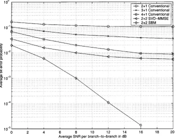
Fig. 7. Average error probability performance of SBM in frequency selective fading channels(D = 0:5) with a single dominant CCI at SIR = 0 dB.
but for dB, over 100-fold decrease in BER
is possible even with dB. Results also
demon-strate that SVD-MMSE becomes worse as SIR decreases, and huge difference compared to SBM can be noticed. However, SVD-MMSE has better performance compared to conven-tional smart antenna system as it could somewhat equalize
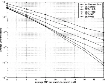
Fig. 8. Average error probability performance of 2+2 SBM in flat fading channels with CCI at SIR = 0 dB in the presence of channel estimation error.
Overall, these results imply that multiple antennas at MS and BS can have very good performance, while reducing the required total number of antennas used, in frequency selective fading channels. Results also reveal that the performance of SBM in frequency selective fading channels is slightly better than that in flat fading and this is because path diversity is obtained by the inherent space–time equalization of SBM. Therefore, multipath could be a desired feature for high-speed wireless communications. In addition, SBM outperforms significantly SVD-MMSE in the presence of CCI. As such, the joint optimization of antenna weights at BS and MS is important.
V. DISCUSSION
The results in the previous section indicate that we can achieve useful improvements in performance compared with existing systems but there are additional considerations such as computational load, channel estimation, and channel errors, and we wish to briefly discuss them.
A. Computational Load
The computational requirement for implementing the joint smart antennas can be large when or is large. The com-putation of (26) and (27) requires several matrix multiplications involving , and , each of sizes,
, and , respectively. Additionally, the inverse of and the eigenvectors of are needed to be computed.
Several possibilities are available for complexity reduction. For instance, it is possible to group the packet into many sub-packets and calculate the weights for the subsub-packets in order to
avoid computing matrix operations with high dimensions. Per-formance, however, would be degraded due to the loss of some path diversity. In addition, it is also possible to add in a cyclic prefix to the signals before transmission so that discrete Fourier transform (DFT) and inverse discrete Fourier transform (IDFT) matrices could be used for diagonalization, as in orthogonal fre-quency-division multiplexing (OFDM) systems.
B. Channel Matrix Estimation
The calculation of the weights (26) and (27) requires that the channel be estimated. Using pilot tones [29], the channel re-sponse can be measured and the matrix can be con-structed by using (2) and (5). In TDD systems, pilot tones on the downlink can be used to estimate the uplink channel since the channels are reciprocal. For frequency division duplex (FDD) systems, feedback of the channel estimations would be neces-sary.
Estimating the correlation matrix and reference correlation vector can be found from
(43)
and
(44)
by using a reference sequence reception period [30]. The corre-lation matrix of the undesired signal at the mobile can then be estimated from
(45)
C. Sensitivity to Channel Matrix Errors
In general, channel estimation will contain some error de-pending on the channel quality as well as the ability of the channel estimation method used. In order to estimate the system performance of SBM in a more realistic way, the perfor-mance of SBM in which the channel and feedback information are in error is investigated.
To study the sensitivity of our system to channel errors, we model the estimation error, , as zero-mean complex AWGN with variance , so that
for and (46)
for (47)
where and are the estimates of (elements of
) and (elements of ), respectively. To characterize the errors, we define the term, signal-to-error ratio (SER), which is
given by or .
In Fig. 8, results are provided for flat fading
chan-nels in the presence of CCI with dB for
dB. Note that when dB,
nearly the same performance is obtained. However, as SER decreases, the degradation becomes larger. Results reveal that as long as SER is greater than 15 dB, the performance has only little degradation. Accordingly, in interference limited environments, accurate channel estimation becomes important.
VI. CONCLUSION
The investigation presented here has demonstrated the use of smart antennas at the base and mobile stations for frequency selective and frequency flat fading channels in the presence of interference. Analytical expressions for the jointly optimized antenna weights have been obtained and these reduce to ex-isting expressions for the flat fading situation. Simulation re-sults reveal that reduction in average bit-error probability by at least one order of magnitude with flat and selective fading with CCI is possible by SBM compared to conventional sys-tems. For example, when the normalized rms delay spread is
0.5 and dB, 2 2 SBM for SNR greater than 12dB
has BER over 100 fold less than a 4 1 conventional system. In addition, our system has also been compared with a SVD scheme with MMSE applied at the receiver. Results conclude that the joint optimization of antenna weights is extremely im-portant and more than 100 fold decrease in is possible when interference is present.
The implementation of the system, however, requires that multiple antennas and signaling overheads be incorporated into the MS. Additionally, a larger computational load is also im-posed. Consequently, we suggest its suitability for high speed data communications for wireless computing applications in combination with recent advances in antenna design.
APPENDIX
Define a set of hermitian matrices . For
, the matrices are defined by
(48)
and
(49)
where is hermitian and positive definite, and are column vectors. It follows that:
(50)
with equality if and only if
(51)
is satisfied.
Proof: From the definition, it can be seen that for
, we have the following recursive relation
(52)
Using the mathematical theory [31] that for a matrix where and are square matrices of the same size, and is a column vector, can be expressed as
(53)
Letting , we get
(54)
Now, for any column vector , our objective is to find the upper bound of
(55)
and the condition provides equality. To find the upper bound, let us first consider the case for . This gives
(56)
where the equality holds when
(57)
Repeatedly using (56) and (57), we then have
(58)
The upper bound can be obtained when all the equalities hold. This is achieved when the following set of equations is satisfied:
To simplify this condition, let us consider the general equation
(60)
However, we know from (59) that , as such
(61)
Then, repeatedly doing the steps (60) and (61), we have
(62)
Using the above results, we can rewrite the condition (59) as
(63)
and this firms up the proof.
ACKNOWLEDGMENT
The authors would like to thank the anonymous reviewers for their useful and constructive comments. In particular, they would like to acknowledge one of the reviewers of the paper who pointed out that under the assumption of a unitary transmit matrix their solution is optimal for maximizing capacity [10], [11]. This can be shown by a straightforward SVD approach with prewhitening at the receiver.
REFERENCES
[1] K. B. Letaief, J. C.-I. Chuang, and R. D. Murch, “A high-speed trans-mission method for wireless personal communications,” in Wireless
Per-sonal Communications. Norwell, MA: Kluwer, 1996, pp. 299–317. [2] C. G. Günther, J. E. Padgett, and T. Hattori, “Overview of wireless
per-sonal communications,” IEEE Commun. Mag., vol. 33, pp. 28–41, Jan. 1995.
[3] N. Seshadri, A. F. Naguib, V. Tarokh, and A. R. Calderbank, “Space-time coded modulation for high data rate wireless communications,” in Proc.
IEEE Globecom, Phoenix, AZ, Nov. 1997, pp. 102–109.
[4] Y. Chen, K. B. Letaief, and J. C.-I. Chuang, “Soft-output equalization and TCM for wireless personal communication systems,” IEEE J. Select.
Areas Commun., vol. 16, pp. 1679–1690, Dec. 1998.
[5] J. H. Winters, “Signal acquisition and tracking with adaptive arrays in the digital mobile radio system IS-54 with flat fading,” IEEE Trans. Veh.
Technol., vol. 42, pp. 377–384, Nov. 1993.
[6] J. Fuhl and A. F. Molisch, “Capacity enhancement and BER in a com-bined SDMA/TDMA system,” in IEEE Vehicular Technology Conf., vol. 3, New York, Apr. 1996, pp. 1481–1485.
[7] K. J. R. Liu, F. R. Farrokhi, and L. Tassiulas, “Transmit and receive diversity and equalization in wireless networks with fading channels,” in Proc. IEEE Globecom, Phoenix, AZ, Nov. 1997, pp. 1193–1198. [8] R. Schmalenberger and J. J. Blanz, “Multi antennaC=I balancing in
the downlink of digital cellular mobile radio systems,” in Proc. IEEE
Vehicular Technology Conf., Phoenix, AZ, May 4–7, 1997, pp. 607–611.
[9] C. R. Rowell and R. D. Murch, “A capacitively loaded PIFA for compact mobile telephone handsets,” IEEE Trans. Antennas Propagat., vol. 45, pp. 837–842, May 1997.
[10] G. J. Foschini, “Layered space-time architecture for wireless communi-cation in a fading environment when using multiple antennas,” Bell Lab.
Tech. J., vol. 1, no. 2, pp. 41–59, 1996.
[11] G. G. Raleigh and J. M. Cioffi, “Spatio-temporal coding for wireless communications,” in Proc. IEEE Globecom, London, U.K., Nov. 1996, pp. 1809–1814.
[12] J. B. Andersen, “Intelligent antennas in a scattering environment—An overview,” in Proc. IEEE Globecom, vol. 6, Sydney, Australia, Nov. 1998, pp. 3199–3203.
[13] , “Array gain and capacity for known random channels with mul-tiple element arrays at both ends,” IEEE J. Select. Areas Commun., vol. 18, pp. 2172–2178, Nov. 2000.
[14] , “Intelligent antennas in personal communications,” presented at the IEEE Int. Conf. Personal Wireless Communications, Jaipur, India, Feb. 1999.
[15] R. Kohno, “Spatial and temporal communication theory using software antennas for wireless communications,” in Int. Symp. Personal, Indoor,
Mobile Radio Communication, Helsinki, Finland, Sept. 1–4, 1997, pp.
293–321.
[16] J. Salz, “Digital transmission over cross-coupled linear channels,” ATT
Tech. J., vol. 64, pp. 1147–1159, July 1985.
[17] J. Yang and S. Roy, “On joint transmitter and receiver optimization for multiple-input-multiple-output (MIMO) transmission systems,” IEEE
Trans. Commun., vol. 42, pp. 3221–3231, Dec. 1994.
[18] K.-K. Wong, K. B. Letaief, and R. D. Murch, “Investigating the perfor-mance of smart antenna systems at the mobile and base stations in the down and uplinks,” Proc. IEEE Vehicular Technology Conf., vol. 2, pp. 880–884, May 17–21, 1998.
[19] K.-K. Wong, R. S.-K. Cheng, K. B. Letaief, and R. D. Murch, “Adaptive antennas at the mobile and base stations in an OFDM/TDMA system,”
IEEE Trans. Commun., vol. 49, pp. 1–8, Jan. 2001.
[20] J. H. Winters, “On the capacity of radio communication systems with diversity in a Rayleigh fading environment,” IEEE J. Select. Areas
Commun., vol. SAC-5, pp. 871–878, June 1987.
[21] J. H. Winters, J. Salz, and R. D. Gitlin, “The impact of antenna diver-sity on the capacity of wireless communication systems,” IEEE Trans.
Commun., vol. 42, pp. 1740–1751, Feb. 1994.
[22] J. C.-L. Ng, K. B. Letaief, and R. D. Murch, “Trade-offs between di-versity combining and equalization for wireless LANs,” in Proc. IEEE
Vehicular Technology Conf., Phoenix, AZ, May 4–7, 1997, pp. 875–879.
[23] G. H. Golub and C. F. Van Loan, Matrix Computations. Baltimore, MD: The Johns Hopkins Univ. Press, 1996.
[24] L. F. Chang and J. C.-I. Chuang, “Diversity selection using coding in a portable radio communications channel with frequency-selective fading,” IEEE J. Select. Areas Commun., vol. 7, pp. 89–97, Jan. 1989. [25] K. B. Letaief, K. Muhammad, and J. S. Sadowsky, “Fast simulation
of DS/CDMA with and without coding in multi-path fading channels,”
IEEE J. Select. Areas Commun., vol. 15, pp. 626–639, May 1997.
[26] T. A. Russell, C. W. Bostian, and T. S. Rappaport, “A deterministic approach to predicting microwave diffraction by buildings for mi-crocellular systems,” IEEE Trans. Antennas Propagat., vol. 41, pp. 1640–1649, Dec. 1993.
[27] J. Salz and J. H. Winters, “Effect of fading correlation on adaptive ar-rays in digital mobile radio,” IEEE Trans. Veh. Technol., vol. 43, pp. 1049–1057, Nov. 1994.
[28] J. C.-I. Chuang, “The effects of time delay spread on portable radio com-munications channels with digital modulation,” IEEE J. Select. Areas
Commun., vol. JSAC-5, pp. 879–889, June 1987.
[29] J. K. Cavers, “An analysis of pilot assisted modulation for Rayleigh fading channels,” IEEE Trans. Veh. Technol., vol. 40, pp. 686–693, Nov. 1991.
[30] K. Yokohata, Y. Ogawa, and K. Itoh, “Spatial-domain path-diversity using an adaptive array for mobile communications,” in Proc. IEEE Int.
Conf. Universal Personal Communications, Nov. 1995, pp. 600–604.
[31] R. T. Compton Jr., Adaptive Antennas: Concept and
Perfor-mance. Englewood Cliffs, NJ: Prentice-Hall, 1988.
Kai-Kit Wong (S’99) was born in Hong Kong in 1973. He received the B.Eng. and M.Phil. degrees in electronic engineering from the Hong Kong University of Science and Technology, Clear Water Bay, Hong Kong, in 1996 and 1998 respectively. He is currently working toward the Ph.D. degree in electrical and electronic engineering also at the Hong Kong University of Science and Technology, Clear Water Bay, Hong Kong.
He has worked in several areas including smart an-tennas, space–time coding, and equalization. His cur-rent research interest centers around the joint optimization of smart antennas for multiuser wireless communications.
Ross D. Murch (S’85–M’87–SM’98) received the B.S. and Ph.D. degrees in electrical and electronic engineering from the University of Canterbury, New Zealand, in 1986 and 1990, respectively. He was ranked first in his undergradutate class.
From 1992–1998, he was an Assistant Professor with the Department of Electrical and Electronic Engineering, Hong Kong University of Science and Technology, Clear Water Bay, Hong Kong, and since 1998, he has been an Associate Professor there. From 1990–92, he was a Post-Doctorate Fellow with the Department of Mathematics and Computer Science at Dundee University, Scotland. His current research interests include smart antenna systems, compact antenna design, and propagation characterization for wireless communications. He has several US patents related to wireless communication, over 100 published papers, and acts as a consultant for industry on occasions. He is also the founding Director of the Center for Wireless Information Technology, which was begun in August 1997. From August–December 1998, he was on sabbatical leave with Allgon Mobile Communications (manufactured one million antennas per week), Stockholm, Sweden and AT&T Research Labs, Newman Springs, NJ.
Dr. Murch is an Editor for the IEEE JOURNAL OF SELECTED AREAS IN
COMMUNICATIONSWireless Series and acts as a reviewer for several journals. He is a Chartered Engineer and a member of the Institute of Electrical Engineering (U.K.). In 1993 and 1996, he won an URSI Young Scientist and Engineering Teaching Excellence Appreciation awards, respectively. During his undergraduate work, he was the recipient of several academic prizes including the John Blackett Prize for engineering and also the Austral Standard Cables prize. During his graduate work, he was awarded a RGC scholarship and was also a New Zealand Telecom bursar.
Khaled Ben Letaief (S’85–M’86–SM’97) received the B.S. degree with distinction in electrical engi-neering from Purdue University, West Lafayette, IN, in December 1984. He received the M.S. and Ph.D. degrees in electrical engineering from Purdue University, in August 1986, and May 1990, respectively.
From January 1985 and as a Graduate Instructor in the School of Electrical Engineering at Purdue Uni-versity, he has taught courses in communications and electronics. From 1990 to September 1993, he was a Faculty Member in the Department of Electrical and Electronic Engineering at the University of Melbourne, Australia, where he was also a Member of the Center for Sensor Signal and Information Systems. Since September 1993, he has been with the Department of Electrical & Electronic Engineering, Hong Kong University of Science & Technology (HKUST), Clear Water Bay, Hong Kong, where he is now a Professor of Electrical and Electronic Engineering. From 1995 to 1998, he served as the Director of the Undergraduate Studies program in the Department. His current research interests include wireless and mobile communications, OFDM, space-time processing for wireless systems, multiuser detection, wireless multimedia communications, and CDMA systems. In 1990, Dr. Letaief was awarded by Purdue University the Mangoon Teaching Award. In Spring 1995, Fall 1996, Fall 1997, and Spring 1999, he was awarded the Teaching Excellence Appreciation Award by the School of Engineering at HKUST. He is also the 1998 university recipient of the Michael G. Gale Medal for Distinguished Teaching (Highest university-wide teaching award and only one recipient/year is honored for his/her contributions). He has been an active member of various professional societies and has published papers in several journals and international conference proceedings. He has served on the editorial board of various journals including the Editor for Wireless Systems of the IEEE TRANSACTIONS ON COMMUNICATIONS, a Technical Editor of the IEEE COMMUNICATIONS MAGAZINE, an Editor of
Wireless Personal Communications, and a Guest Editor of the 2000 Wireless
Personal Communications Special Issue on Intelligent Multimedia Systems, Terminals, and Components. He is also an Advisory Board member of Wireless Communications and Mobile Computing and has been a Guest Editor of the 1997 IEEE JOURNAL ON SELECTED AREAS IN COMMUNICATIONS Special Issue on Computer-Aided Modeling, Analysis and Design of Communications Links. He served as the Technical Program Chair of the 1998 IEEE Globecom Mini-Conference on Communications Theory (CTMC’98), held in Sydney, Australia. He is also the Co-Chair of the 2001 IEEE ICC Communications Theory Symposium, held in Helsinki, Finland. In January 2001, he was appointed the Editor-in-Chief of the IEEE JOURNAL ONSELECTEDAREAS IN