R E S E A R C H
Open Access
Joint source and relay optimization for
interference MIMO relay networks
Muhammad R. A. Khandaker
*and Kai-Kit Wong
Abstract
This paper considers multiple-input multiple-output (MIMO) relay communication in multi-cellular (interference) systems in which MIMO source-destination pairs communicate simultaneously. It is assumed that due to severe attenuation and/or shadowing effects, communication links can be established only with the aid of a relay node. The aim is to minimize the maximal mean-square-error (MSE) among all the receiving nodes under constrained source and relay transmit powers. Both one- and two-way amplify-and-forward (AF) relaying mechanisms are considered. Since the exactly optimal solution for this practically appealing problem is intractable, we first propose optimizing the source, relay, and receiver matrices in an alternating fashion. Then we contrive a simplifiedsemidefinite programming (SDP) solutionbased on the error covariance matrix decomposition technique, avoiding the high complexity of the iterative process. Numerical results reveal the effectiveness of the proposed schemes.
Keywords: Interference, MIMO, Two-way, Relay, Optimization
1 Introduction
Due to scarcity of frequency spectrum in practical wire-less networks, multiple communicating pairs are moti-vated to share a common time-frequency channel to ensure efficient use of the available spectrum. Co-channel interference (CCI) is, however, one of the main dete-riorating factors in such networks that adversely affect the system performance. The impact is more obvious in 5G heterogeneous networks where there is oceanic vol-ume of interference due to hyper-dense frequency reuse among small-cell and macro cell base stations. Therefore, it is important to develop schemes to mitigate the CCI, which has been a major research direction in wireless communications over the past decades.
In the literature, various schemes have been pro-posed to control CCI at an acceptable level. A conven-tional approach in MIMO systems is to exploit spatial diversity for suppressing CCI [1]. Such spatial diversity technique has been used to solve many power control problems in interference systems for different network setups. In [2], a power control scheme has been designed
*Correspondence: [email protected]
Department of Electronic and Electrical Engineering, University College London, Torrington Place, London WC1E 7JE, UK
with receive diversity only, whereas joint transmit-receive beamforming has been considered in [2, 3] for interfer-ence systems. However, the incorporation of the spatial diversity at the transmitter side in [3], results in lower total transmit power compared to that in [2].
On the other hand, there is synergy between multiple antenna and relaying technologies. The latter is partic-ularly useful to reestablish communications in case of a broken channel between source and destination. Hence, relaying has been considered in interference networks in order to afford longer source-destination distance [4–7]. Both [4, 5] considered network beamforming for minimiz-ing total relay transmit power, whereas in [7], an iterative transceiver optimization scheme has been proposed to minimize total source and relay transmit power.
While the works in [2–5, 7] all considered minimiz-ing the total transmit power of interference networks, another important performance metric, which concerns more about the quality of communications, is the mean-square-error (MSE) for signal estimation. In [8–10], the sum minimum MSE (MMSE) was considered to design iterative algorithms for MIMO interference relay sys-tems taking the direct links between the source and des-tination nodes into consideration, and in [11], similar
problem has been considered ignoring the direct links between the communicating parties. Indeed the direct source-destination links can play a vital role in wireless communication systems when the link-strength is signifi-cant. However, multihop communication is motivated by the fact that such direct links may undergo deep shadow-ing effects in many practical scenarios. Hence, many exist-ing works on multihop communications have ignored the direct links. Nonetheless, the sum MMSE criterion runs the risk that some of the receivers may suffer from unac-ceptably high MSEs. Also, the works in [8–10] considered one-way relaying only.
Due to the increasing demands on multimedia appli-cations, in particular, the notion of emerging wireless communications terminologies such as Big data, ultra-high spectral efficiency is essential in future wireless networks, including 5G, to provide ADSL-like user expe-rience aspired by 2020. The abovementioned one-way relay systems suffer from a substantial performance loss in terms of spectral efficiency due to the pre-log factor of 1/2 persuaded by the fact that two channel uses are required for each end-to-end transmission.
Two-way relay systems have hence been proposed to overcome the loss of spectral efficiency in such one-way relay methods [12–14]. Utilizing the concept of analog network coding [14], communication in a two-way relay channel can be accomplished in two phases: the multiple access (MAC) phase and the broadcast (BC) phase. Dur-ing the MAC phase, all the users simultaneously send their messages to an intermediate relay node, whereas in the BC phase, the relay retransmits the received information to the users. As each user knows its own transmitted signals, each user can cancel the self-interference and decode the intended message. The capacity region of multi-pair two-way relay networks in the deterministic channel was char-acterized in [15]. Later in [16], the achievable total degrees of freedom in a two-way interference MIMO relay channel were also studied. Most recently in [17], the transceivers in a full-duplex MIMO interference system were opti-mized based on the weighted sum-rate maximization criterion.
In this paper, we consider a K-user MIMO
interfer-ence system where each of the pairs can communicate only with the aid of a relay node thus ignoring the direct source-destination links. The direct links are understood to be in deep shadowing and hence negligible. Both one-and two-way amplify-one-and-forward (AF) relaying mech-anisms are considered. All nodes are assumed to be equipped with multiple antennas so as to afford simul-taneous transmission of multiple data streams. Our aim is to develop joint transceiver optimization algorithms
for minimizing the worst-user MSE (min-max MSE)1
subject to the source and relay power constraints. It can be verified that the problem is strictly non-convex,
and thus it is difficult to find an analytical solution. To tackle this, we first devise an algorithm to opti-mize the source, relay, and receiver matrices alternat-ingly by decomposing the original non-convex problem into convex subproblems. To avoid the complexity of the iterative process, we then extend the error covari-ance matrix decomposition technique applied to point-to-point MIMO relay systems in [18] to interference MIMO relay systems in this paper. More specifically, under practically reasonable high first-hop signal-to-noise ratio (SNR) assumption, we demonstrate that the prob-lem can be decomposed into two standard semidefinite programming (SDP) problems to optimize source and relay matrices separately. Note that high SNR assump-tion has also been made in [19] to simplify the joint codebook design problem in single-user MIMO relay sys-tems and in [20, 21] for multicasting MIMO relay design. Hence our work is a generalization to multi-pair com-munication scheme taking co-channel interference into account.
The remainder of this paper is lined-up as follows. In Section 2, the interference MIMO relay system model is introduced. The joint optimal transmitter, relay, and receiver beamforming optimization schemes are devel-oped in Section 3 and Section 4, respectively, for one-way and two-one-way relaying. Section 5 provides simulation results to analyze the performance of the proposed algo-rithms in various system configurations before concluding remarks are made in Section 6.
2 System model
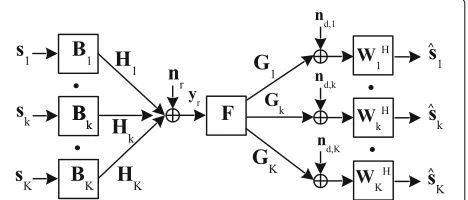
Let us consider a communication scenario, as illustrated in Fig. 1, where each of theKsource nodes communicates with the corresponding destination node sharing the same frequency channel via a common relay node. The direct link between each transmitter-receiver pair is assumed to be broken due to strong attenuation and/or shadowing effects. Thekth source, the relay, and thekth destination nodes are assumed to be equipped withNs,k,Nr, andNd,k antennas, respectively.
3 One-way relaying
In this section, we consider that communication takes place in one direction only. The relay node is assumed to work in half-duplex mode which implies that the actual communication between the source and destina-tion nodes is accomplished in two time slots. In the first time slot, the source nodes transmit the linearly precoded signal vectors Bksk,k = 1,· · ·,K, to the relay node. The received signal vector at the relay node is therefore given by
yr =
K
k=1
HkBksk+nr, (1)
whereHkdenotes theNr×Ns,kGaussian channel matrix between thekth source node and the intermediate relay node,skis theNb,k×1(1≤Nb,k≤Ns,k)transmit symbol vector with covarianceINb,k,Bk is theNs,k×Nb,k source precoding matrix, and nr is the Nr × 1 additive white Gaussian noise (AWGN) vector introduced at the relay node. Let us denoteNb = Kk=1Nb,k as the total num-ber of data streams transmitted by all the source nodes. In order to successfully transmit Nb independent data streams simultaneously through the relay, the relay node must be equipped withNr≥Nbantennas.
After receivingyr, the relay node simply multiplies the signal vector by anNr×Nrprecoding matrixFand trans-mits the amplified version ofyr in the second time slot. Thus the relay’sNr×1 transmit signal vectorxris given by
xr=Fyr. (2)
Accordingly, the signal received at thekth destination node can be expressed as
yd,k=Gkxr+nd,k
=GkFHkBksk desired signal
+GkF K
j=1 j=k
HjBjsj
interference signal
+GkFnr+nd,k noise
, (3)
= ¯Hksk+ ¯nd,k, fork=1,. . .,K, (4)
whereGk denotes theNd,k×Nrcomplex channel matrix
between the relay node and the kth destination node,
nd,k is the Nd,k × 1 AWGN vector introduced at the
kth destination node, H¯k GkFHkBk is the
equiv-alent source-destination channel matrix, and n¯d,k
GkF(Kj=1 j=k
HjBjsj+nr)+nd,kis the equivalent noise vector. All noises are assumed to be independent and identically distributed (i.i.d.) complex Gaussian random variables
with mean zero and varianceσn2, where n∈ {r, d}indicates the noise introduced at the relay or at the destination.
RemarkNote that the interference term in (3) does not appear in the received signal of the single-user MIMO relay system considered in [19] or in the multicasting MIMO relay system considered in[20, 21]. Hence the subsequent analyses remain considerably simpler in[19–21], whereas we need to deal with this troublesome interference term in this paper.
Considering the input-output relationship at the relay node given in (2), the average transmit power consumed by the MIMO relay node is defined as
trE{xrxHr} =tr
FFH , (5)
where tr(·)denotes trace of a matrix, E{·}indicates statisti-cal expectation, andE{yryHr } =
K
k=1HkBkBHkHHk + σr2INrrepresents the covariance matrix of the signal vector received at the relay node.
For signal detection, linear receivers are used at the des-tination nodes for simplicity reasons. DenotingWkas the Nd,k × Nb,k receiver matrix used by the kth destination node, the corresponding estimated signal vectorˆskcan be written as
ˆ
sk =WHkyd,k, fork=1,. . .,K, (6)
where(·)H indicates the conjugate transpose (Hermitian) of a matrix (vector). Thus the MSE of signal estimation at thekth receiver can be expressed as
Ek = tr
EkE
ˆ sk−sk
ˆ sk−sk H
,
= tr
⎛ ⎜ ⎝
INb,k−WHkGkFHkBk−BHkHHkFHGH kWk
+K
j=1WHkGkFHjBjBHj HHj FHGHkWk
+σr2WHkGkFFHGHkWk+σd2WHkWk
⎞ ⎟ ⎠,
= trWHkH¯k−INb,k W
H
kH¯k−INb,k
H+
WHkC¯kWk
, for k=1,. . .,K, (7)
whereEkdenotes the error covariance matrix at thekth receiver, and
¯ Ck
K
j=1 j=k
GkFHjBjBHj HHj FHGHk +σr2GkFFHGkH+σd2INd.
(8)
In the following subsections, we develop optimization approaches that minimize the worst-user MSE among all the receivers subject to source and relay power constraints.
3.1 Problem formulation
In this section, we formulate the joint source and relay precoding optimization problem for MIMO interference systems. Our aim is to minimize the maximal MSE among all the source-destination pairs yet satisfying the trans-mit power constraints at the source as well as the relay nodes. To fulfill this aim, the following joint optimization problem is formulated:
min
{Bk},F,{Wk} max
k Ek (9a)
s.t. trFFH ≤Pr (9b)
trBkBHk ≤Ps,k, fork=1,. . .,K (9c)
where (9b) and (9c), respectively, constrains the transmit power at the relay node and thekth transmitter toPr>0, Ps,k > 0. Our next endeavor is to develop optimal solu-tions for this problem. Note that the problem is strictly non-convex with matrix variables appearing in quadratic form, and hence any closed-form solution is intractable. Therefore, we first resort to developing an iterative algo-rithm for the problem and then propose a sub-optimal solution which has lower computational complexity.
3.2 Iterative joint transceiver optimization
In this subsection, we investigate the non-convex source, relay, and destination filter design problem in an alternat-ing fashion. We tend to optimize one group of variables while fixing the others. Given source and relay matrices
{Bk},F, the optimal receiver matrices{Wk}are obtained through solving the unconstrained optimization problem of minWkEk, sinceEk does not depend onWj, forj =k, andWkdoes not appear in constraints (9b) and (9c). Using
the matrix derivative formulas, the gradient∇WH
k (tr(Ek)) can be written as
∇WHk (tr(Ek))= −GkFHkBk+
K
j=1GkFHjBjBjHHHj FHGHkWk
+σr2GkFFHGH
kWk+σd2Wk, fork=1,. . .,K. (10)
Equating ∇WH
k (tr(Ek)) = 0 yields the linear MMSE receive filter given by
Wk=
K
j=1
GkFHjBjBHj HHj FHGHk+σr2GkFFHGkH+σd2INd,k
−1
×GkFHkBk (11)
where(·)−1indicates the inversion operation of a matrix. Then for given source and receiver matrices {Bk}and
{Wk}, the relay precoding matrixFoptimization problem can be formulated as
min
F maxk Ek (12a)
s.t. trFFH ≤Pr. (12b)
Note that (12) is non-convex with a matrix variable since
F appears in quadratic form in the objective function as well as in the constraint. However, we can reformulate this problem as an SDP using Schur complement [22] as
follows. By introducing a matrix k we conclude from
the second equation in (7) that thek-th link MSE will be upper-bounded if
−WHkGkFHkBk−BHkHHkFHGHkWk
+WHkGkFFHGHkWk k.
(13)
In the above inequality,ABindicates that the matrix
B−Ais positive semidefinite (PSD). Now, by introducing a matrixsuch thatFFH , and a scaler variableτr, the relay optimization problem (12) can be transformed to
min τr,F,{k},
τr (14a)
s.t. tr(k)+trWHkWk +Nb,k≤τr, fork=1,. . .,K, (14b)
k+WHkGkFHkBk+BHkHHkFHGHkWk WHkGkF
FHGHkWk −1
0, fork=1,. . .,K, (14c)
F
FH −1
0 (14d)
where we have used the Schur complement to obtain (14c) and (14d). Note that the problem (14) is an SDP prob-lem which is convex and can, as a result, be efficiently solved using interior-point based solvers [23] at a maxi-mal complexity order ofO(K+2Nr2+Kk=1Nb,k2 +2)3.5 [24]. However, the actual complexity is usually much less in many practical cases. Interested readers are referred to [24] for a detailed analysis of the computational complexity based on interior-point methods.
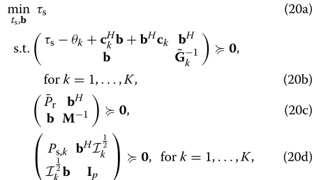
Finally, we optimize the source matrices{Bk}using the relay matrix F and the receiver matrices {Wk} known from the previous steps. Let us defineH˜k,j WHkGkFHj. all the columns of the matrix Bk on top of each other, θk tr(σr2WHkGkFFHGHkWk+σd2WHkWk)+Nb,k, and⊗ indicates matrix Kronecker product. Let us now denote
⎧
where bd(·)constructs a block-diagonal matrix taking the parameter matrices as the diagonal blocks,C˜k,k = ˜Hk,k andC˜k,j = 0Nb,k×Ns,j, ifj = k. The MSE in (15) can be rewritten as
Ek=bHG˜kb−ckHb−bHck+θk. (17)
By introducingMk FHk, the power constraints in (9b) can be rewritten as
bHMb≤ ¯Pr, fork=1,. . .,K, (18) can be written as
min a standard quadratically-constrained quadratic program
(QCQP) which can be solved using off-the-shelf convex optimization toolboxes [23]. In the following, we also provide an SDP formulation of problem (19):
min problem (20) can be solved at a maximal complexity order ofO(Kk=1Nb,k2 +1)3.5 [24]. The proposed iterative opti-mization technique for solving the original problem (9) is summarized in Table 1.
Since in each step of the iterative algorithm we solve a convex subproblem to update one set of variables, the con-ditional update of each set will either decrease or main-tain the objective function (9a). From this observation, a monotonic convergence of the iterative algorithm follows. However, the overall computational complexity of the iter-ative algorithm increases as the multiple of the number of iterations required until convergence. Thus the com-plexity of the iterative algorithms is often reasonably high. Note that the sum-MSE based iterative algorithms pro-posed in [8–10] have similar complexity orders. Hence in the following subsection, we contrive an algorithm for the joint optimization problem such that the computational overhead is substantially reduced.
3.3 Simplified joint optimization algorithm
In the previous subsection, we optimized the source, relay, and receiver matrices in an alternating fashion. Here, we propose a simplified approach to solve problem (9) using the error covariance matrix decomposition tech-nique. The following theorem paves the foundation of the simplified algorithm.
Table 1Iterative solution of problem (9)
1 Randomly initializeFand{Bk}such that the constraints (9b) and (9c) are satisfied.
2 Repeat
(a) Obtain{Wk}as defined in (11) using known{Bk}andF.
(b) Solve the subproblem (14) to updateFusing fixed{Wk}and {Bk}.
(c) Update{Bk}through solving the subproblem (20) usingF and{Wk}known from the previous steps.
Theorem 1For given {Bk} and {Wk}, the optimum relaying matrixFfor minimizing the worst-user MSE has the form:
F=
K
k=1
TkDHk =TDH, (21)
whereT [T1,. . .,TK]andD [D1,. . .,DK]withTk andDk, respectively, defined as
Tkλe,k
K
i=1
λe,iGHi WiWiHGi+λrINr
−1
GHkWk (22)
and
Dk ⎛ ⎝K
j=1
HjBjBHj HHj +σr2INr
⎞ ⎠
−1
HkBk, (23)
λrandλe,k,∀k,are the corresponding Lagrange multipliers as defined in Appendix1.
ProofSee Appendix 1.
Note that Dk =
HkBkBHkHHk +
K
j=1 j=k
HjBjBHj HHj +
σr2INr
−1
HkBk can be regarded as the MMSE receive
filter of the first-hop MIMO channel for thekth transmit-ter’s signal received at the relay node given by (1).
The implication of the structure of the relay amplifying matrix in the proposed simplified design can be observed while applying the following theorem.
Theorem 2The MSE term appearing in (9a) can be equivalently decomposed into
Ek = tr
INb,k+B
H
kHHk−k¯1HkBk −1
(24)
+trBHkHHk−1HkBk −1
+ ˜THGHkGkT˜ −1
,
wherek¯−HkBkBHkHHk =Kj=1 j=k
HjBjBHj HHj +σn2INr
andT˜ is defined in Appendix2.
ProofSee Appendix 2.
Even given the structure, an analytical optimal solution to the joint optimization problem is still difficult to obtain due to the cross-link interference from the relay node to the destination nodes. Therefore, we resort to develop an efficient suboptimal solution. The following proposi-tion provides the foundaproposi-tion of the proposed simplified suboptimal solution.
Proposition 1In the practically reasonably high SNR regime, the termBHkHHk ×−1HkBkin(24)can be approx-imated asBHkHHk−1HkBk ≈INb,k.
Proof See Appendix 3.
The result in Proposition1 is guided by the observa-tion that the eigenvalues of BHkHHk−1HkBk approach unity with increasing first-hop SNR. It will be demon-strated in Section 5 through numerical simulations that such an approximation results in negligible performance loss while reducing the computational complexity signifi-cantly. ApplyingProposition1, the transmit power of the relay node defined in (5) can be expressed as trFFH =
tr(TB˜ HkHHk−1HkBkT˜H)=tr(T˜T˜H). Therefore, problem (9) can be approximated as
min
{Bk},{Wk},T˜ max
k tr
INb,k+B
H
kHHk−k¯1HkBk −1
+trINb,k+ ˜T HGH
kGkT˜ −1
(25a)
s.t. trBkBHk ≤Ps,k, fork=1,. . .,K, (25b)
tr T˜T˜H
≤Pr. (25c)
Note that the optimal receiver matrices {Wk} can be obtained as in (11). Interestingly, the source and relay opti-mization variables {Bk} andT˜ are separable both in the objective function as well as in the constraints in prob-lem (25). Therefore, applying the results fromTheorem2 and Proposition1, we can decompose the problem (25) into the following source precoding matrices optimization problem:
min
{Bk} max
k tr
INb,k+B
H
kHHk−k¯1HkBk −1
(26a)
s.t. tr(BkBHk)≤Ps,k, fork=1,. . .,K, (26b)
and the relay amplifying matrix optimization problem:
min
˜ T
max
k tr
INb,k+ ˜T HGH
kGkT˜ −1
(27a)
s.t. trT˜T˜H≤Pr. (27b)
Note that the objective function in (26a) can be inter-preted as the MSE of thekth transmitter’s signal vector
sk. In particular, the equivalent received signal for thekth transmitter’s signal in the first hop received at the relay node is given by y(rk) = HkBksk +
K
Given the corresponding MMSE receiverDk, (26a) can be an auxiliary variablets, problem (26) can be rewritten as the following second-order cone program (SOCP):
min
which can be efficiently solved by standard optimization packages at a complexity order ofO(Kk=1Nb,k2 +1)3 [24]. Thus, we can update{Dk}and{Bk}in an alternating fashion.
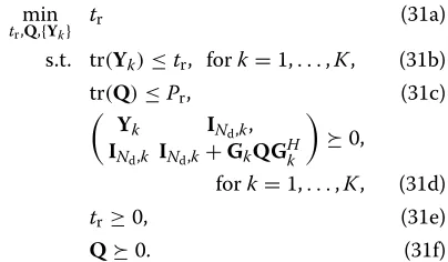
Regarding the relay amplifying matrix optimization, by introducing T˜HT˜ Q, the relay matrix optimization problem (27) can be equivalently transformed to
min
Let us now introduce a matrix variable Yk
INd,k+GkQGHk −1
, and a scalar variabletr. Using these variables, the relay optimization problem (30) can be equivalently rewritten as the following SDP:
min
Problem (31) is convex and the globally optimal solution can be easily obtained [23]. The complexity order of solv-ing problem (31) is at mostO(Kk=1Nb,k2 +Kk=1Nd,k2 + K+2)3.5 [24]. Note that in the simplified algorithm, only the source matrices are obtained in an alternating fashion.
The overall joint optimization procedure is summarized in Table 2.
4 Two-way relaying
Two-way relaying is being considered as a promising tech-nique for future generation wireless systems since two-way relaying can significantly improve spectral efficiency. Hence, in this section, we consider two-way relaying in an interference MIMO relay system where each pair of users transmit signals to each other through the assist-ing relay node. The information exchange in the two-way relay channel is accomplished in two time slots: MAC phase and the BC phase. During the MAC phase, all the users simultaneously send their messages to the relay node. Thus the signal vector received at the relay node during the MAC phase can be expressed as
yr = AWGN vector received at the relay node.
Upon receivingyr, the relay node linearly precodes the signal vector by anNr×Nramplifying matrixFand trans-mits the Nr × 1 precoded signal vector xr in the MAC phase:
xr=Fyr. (33)
The received signal at thekth user in the BC phase is given by AWGN vector at thekth destination node. As in the case of the one-way relaying system, all noises are assumed to be i.i.d. complex Gaussian random variables with mean zero and varianceσn2.
Table 2Proposed simplified algorithm for solving problem (9)
1 InitializeBk,∀k, satisfying the constraints (29c).
2 Repeat
(a) UpdateDk,∀k, as in (23).
(b) UpdateBk,∀k, through solving the subproblem (29).
3 Until convergence.
Since the transmitting node k knows its own signal vector sk and the full CSI of the corresponding source-destination link HTkFHkBk, each transmitter can com-pletely cancel the self-interference component in (34). Thus, the effective received signal vector at thekth receiv-ing node is given by
yk=HTkFHk¯Bk¯sk¯+H
Using (33), the transmission power required at the relay node can be defined as
trE%xrxHr covariance matrix of the signal received at the relay node from all the transmitters. Furthermore, the MSE of the estimated signal using anNd×Nblinear weight matrixWk at thekth receiving node can be expressed as
Ek=tr
Similar to the case of one-way relaying, the problem of optimizing the transmit, relay, and receive matrices for the two-way scenario can be formulated as
min
where (39b) and (39c) indicates the corresponding trans-mit power constraints.
4.1 Iterative joint transceiver optimization
Similar to the one-way relaying scenario, it can be shown that the transmitter, relay, and receiver matrices can be optimized in an alternating fashion through solving con-vex sub-problems. In each iteration of the algorithm, the receiver weight matrices are updated as follows:
Wk =
The relay beamforming matrixFis optimized through
solving the following SDP problem:
min
where we have defined
'
4.2 Simplified non-iterative approach
Assuming moderate SNR in the MAC phase, it can be shown, similar to the one-way relaying case, that the generic structure of the relay matrixFis defined asF = TDH. Using this particular structure of F, the MSE at thekth receiver can be equivalently decomposed into two parts as shown below:
Ek = tr
INb,k+B
H
kHHk−k¯1HkBk −1
+tr
BHkHHk−¯1 k HkBk
−1
+ ˜THH∗k¯HTk¯T˜ −1
. (45)
Accordingly, the joint precoding design problem (25) can be decomposed into two sub-problems, namely, the source precoding matrices optimization problem:
min
{Bk} max
k tr
INb,k+B
H
kHHk−¯k1HkBk −1
(46a)
s.t. trBkBHk ≤Ps,k, fork=1,. . .,K, (46b)
and the relay beamforming matrix optimization problem:
min
˜ T
max
k tr
INb,k+ ˜T HH∗
¯ kH
T ¯ kT˜
−1 (47a)
s.t. trT˜T˜H≤Pr, (47b)
which can be solved following the similar approach as for the one-way relaying scenario.
5 Numerical simulations
In this section, we analyze the performance of the pro-posed one- and two-way MIMO relay interference system optimization algorithms through numerical examples. For simplicity, we assume that the source and the destination nodes are equipped withNsandNdantennas each, respec-tively, andPs,k = Ps, ∀k. We simulated a flat Rayleigh fading environment such that the channel matrices have zero-mean entries with variances 1/Ns for Hk, ∀k, and 1/NrforGk, ∀k. All the simulation results were obtained by averaging over 500 independent channel realizations.
The performance of the proposed min-max MSE algo-rithms have been compared with that of the naive AF (NAF) algorithm in terms of both MSE and bit error rate (BER). The NAF algorithm is a simple baseline scheme that forwards the signals at the transmitters and the relay node assigning equal power to each data stream. In par-ticular, the source and the relay matrices, in their simplest forms, in the NAF scheme are defined as
' Bk=
$
Ps/NsINs, fork=1,. . .,K,
F=$Pr/tr()INr.
(48)
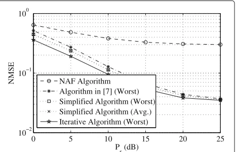
In the first example, we compare the performance of the proposed min-max MSE-based one-way algorithms with
that of the sum-MSE minimization algorithm in [8] as well as the NAF approach in terms of the MSE
normal-ized by the number of data streams (NMSE) withK = 3,
Ns = 3,Nr = 9, andNd = 3. Figure 2 shows the NMSE performance of the algorithms versus transmit powerPs with fixedPr =20 dB. Note that for the proposed simpli-fiednon-iterativealgorithm, we plot the NMSE of the user with the worst channel (Worst) as well as the average per-stream MSE of all the users (Avg.). On the other hand, for the rest of the algorithms, the worst-user NMSE has been plotted. The results clearly indicate that the proposed joint optimization algorithms consistently yield better perfor-mance compared to the existing schemes. It can also be revealed that the proposed iterative algorithm has the best MSE performance compared to the other approaches over the entirePs range. It is no surprise that the NAF algo-rithm yields much higher MSE compared to the other schemes since the NAF algorithm performs no optimiza-tion operaoptimiza-tion. Most importantly, the iterative sum-MSE minimization algorithm in [8] always penalizes the user with the worst channel condition.
Since the NAF algorithm does not allocate the trans-mit power optimally and equally divides the power among multiple data streams instead, the inter-stream interfer-ence and the inter-user interferinterfer-ence increase significantly at higher transmit power. Hence, the MSE of the NAF algorithm does not improve notably at higher transmit power.
Further analysis of the results in Fig. 2 reveals that the proposed simplified algorithm yields the worst-user MSE performance which is comparable to that of the itera-tive algorithm, even at low Ps region. This observation illustrates that the approximation made in the simplified algorithm encounters negligible performance loss com-pared to the iterative optimal design. On the other hand, the computational complexity of the proposed simplified optimization is less than that of even one iteration of the
0 5 10 15 20 25
10−2
10−1
100
P
s (dB)
NMSE NAF Algorithm
Algorithm in [7] (Worst) Simplified Algorithm (Worst) Simplified Algorithm (Avg.) Iterative Algorithm (Worst)
Table 3Iterations required till convergence in the proposed algorithm
Ps(dB) 0 5 10 15 20 25
Iterations 3 3 3 4 5 5
iterative design, making it much more attractive for prac-tical interference MIMO relay systems. The number of iterations required for convergence up to 10−3 in terms of MSE in a random channel realization for the iterative algorithm are listed in Table 3.
In the next example, we focus on the proposed simpli-fied optimization scheme and compare its performance with that of the proposed iterative approach and the NAF algorithm in terms of BER. Quadrature phase-shift keying (QPSK) signal constellations were assumed to modulate the transmitted signals and maximum-likelihood detec-tion is applied at the receivers. We setK=3,Ns=2,Nr =
6, Nd = 3, and transmit 1000Ns randomly generated
bits from each transmitter in each channel realization. The BER performance of the algorithms are shown in Fig. 3 versus Ps with Pr = 20 dB. As we can see, the proposed simplified algorithm yields a much lower BER compared to the conventional NAF scheme. Compared with the iterative approach the simplified algorithm has much lower computational task at the cost of marginal performance loss.
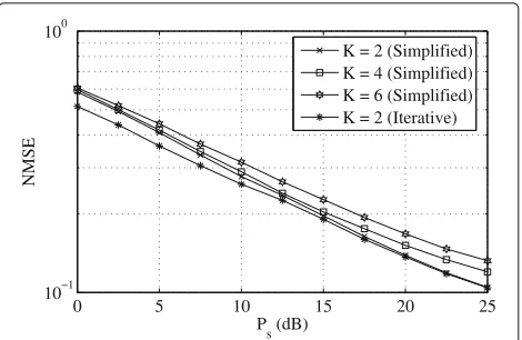
In the last couple of examples, we analyze the per-formance of the two-way MIMO relaying scheme. The NMSE performance of the two-way relaying algorithms is shown for different number of communication links
K in Fig. 4. This time we set Ns = 2,Nr = KNs, and
Nd = 6 to plot the NMSE of the proposed algorithms
versus Ps withPr = 20 dB. It can be clearly seen from Fig. 4 that as the number of links increases, the worst-user
0 5 10 15 20 25
10−3
10−2
10−1
100
Ps (dB)
BER
NAF Algorithm
Simplified Algorithm (Worst) Simplified Algorithm (Avg.) Iterative Algorithm (Worst)
Fig. 3Example 2: BER versusPs.K=3,Ns=2,Nr=6,Nd=3, Pr=20 dB
0 5 10 15 20 25
10−1
100
P
s (dB)
NMSE
K = 2 (Simplified) K = 4 (Simplified) K = 6 (Simplified) K = 2 (Iterative)
Fig. 4Example 3: MSE versusPsin two-way relaying. Varying number of links,Ns=2,Nr=KNs,Nd=6,Pr=20 dB
MSE keeps increasing. This is due to the additional cross-link interferences generated by the increased number of active users.
In Fig. 5, the BER performance of the proposed two-way relaying algorithms has been compared with the sum-MSE-based algorithms originally proposed for one-way relaying in [8–10]. QPSK signal constellations were assumed to modulate the transmitted signals. We setNs = 2,K = 3,Nr = KNs,Nd = 6,Pr = 20 dB, and transmit 1000Ns randomly generated bits from each transmitter in each channel realization. Most importantly, the itera-tive sum-MSE minimization algorithms in [8–10] always penalize the user with the worst channel condition in the two-way relaying system.
6 Conclusions
We considered a two-hop interference MIMO relay sys-tem and developed schemes to minimize the worst-user
0 5 10 15 20 25
10−2
10−1
100
P
s (dB)
BER
Iterative Algorithm Simplified Algorithm Sum−MSE Algorithm
MSE of signal estimation for both one- and two-way relay-ing schemes. At first, we proposed an iterative solution for both relaying schemes by solving several convex sub-problems alternatingly and in an iterative fashion. Then to reduce the computational overhead of the optimiza-tion approach, we develop a simplified non-iterative algo-rithm using the error covariance matrix decomposition technique based on the high SNR assumption. Simula-tion results have illustrated that the proposed simpli-fied approach performs nearly as well as the iterative approach, while offering significant reduction in compu-tational complexity.
Endnote
1The min-max MSE criterion is considered by many
to be more desirable than the min-sum MSE criterion in [8–10] because fairness is imposed and weaker users are not being sacrificed for the minimization of the sum.
Appendix 1: Proof of Theorem 1
For given{Bk}and{Wk}, problem (9) reduces to
min
F τ (49a)
s.t. Ek ≤τ, fork=1,. . .,K, (49b)
trFFH ≤Pr. (49c)
The Lagrangian function of problem (49) can be written as
The derivative of the Lagrangian function over FH is given by
Rearranging the terms in (51),∂∂FLH can be expressed as
∂L
Appendix 2: Proof of Theorem 2 The MSE in (9a) can be rewritten as
Ek = and the first term in (59) whereas the matrix identity
in (59) is irrelevant toF. Hence for given source matrices, the problem of optimizingFcan be simplified as
min
Let us write the eigenvalue decomposition (EVD)
GHkGk = VggVHg and the singular value decomposi-tion (SVD)−12HkBk =UψψVHψ. The following lemma defines the optimalF˜.
Lemma 1([25] Lemma 2) For matrices A,T¯,H of dimensions m ×n, l × m, and k ×l, respectively, with k,l,m ≥ n, r rank(H) ≥ n and rank(T¯) = n, the solution to the optimization problem
min
A, respectively, with the diagonal elements ofhanda sorted in a decreasing order, andV˜hcontains the leftmost n columns ofVh.
According to Lemma 1, the optimalF˜ in (61) has the SVD F˜ = ˜VgfUHψ where V˜g contains the left-most columns of Vg corresponding to the non-zero
eigenval-ues. Then after some simple manipulations, F˜ can be
rewritten asF˜ = ˜Vgf−ψ1VHψVψψUHψ = ˜TBHkHHk−
1 2
where T˜ V˜gf−ψ1VHψ. HenceF can be expressed as
F = ˜TBHkHHk−1. Interestingly,F= ˜TBHkHHk−1can be expressed asF = ˜TD˜H, which is structurally identical to the one defined in Theorem 1.
Applying this structure of the relay matrix, the second term in (59) can be written as
tr
Thus the MSE in (9a) can be expressed as the sum of two MSEs given by
Appendix 3: Proof of Proposition 1
Assuming that the first-hop SNR is reasonably high, it emerges thatKj=1HjBjBHj HHj σr2INr where A B effectively means that the eigenvalues ofA−Bare much greater than zero. Hence,
BHkHHk−1HkBk = BHkHHk
of generality, we express Uk =
diagonal. ThusHkBk = Uk¯
Similarly, we obtain the following EVD
K
Nr−Nb,k unitary matrices, respectively. As a conse-quence, we obtain
Substituting (71) into (68), we obtain
BHkHHk
This work is supported by EPSRC under grant EP/K015893/1.
Authors’ contributions
MRAK formulated the optimization problems, designed the proposed solutions, performed numerical simulations, and prepared the initial draft as well as the revision. K-KW managed funding for the research, modified solution pattern, verified mathematical derivations, checked and analyzed the simulation results, and improved the writeup. Both authors read and approved the final manuscript.
Authors’ information
Muhammad R. A. Khandaker received the B.Sc. degree (Hons.) in computer science and engineering from Jahangirnagar University, Dhaka, Bangladesh, in 2006, the M.Sc. degree in telecommunications engineering from East West University, Dhaka, in 2007, and the Ph.D. degree in electrical and computer engineering from Curtin University, Australia, in 2013. He was a Junior Hardware Design Engineer with Visual Magic Corporation Ltd., in 2005. He joined the Department of Computer Science and Engineering, IBAIS University, Dhaka, in 2006, as a Lecturer. In 2007, he joined the Department of Information and Communication Technology, Mawlana Bhasani Science and Technology University, as a Lecturer. He joined the Institute of Information Technology, Jahangirnagar University, Dhaka, in 2008, as a Lecturer. Since 2013, he has been a Postdoctoral Research Associate with the Department of Electronic and Electrical Engineering, University College London, UK. He received the Curtin International Postgraduate Research Scholarship for his Ph.D. studies in 2009. He also received the Best Paper Award at the 16th Asia-Pacific Conference on Communications, Auckland, New Zealand, 2010. Kai-Kit Wong received the B.Eng, M.Phil., and Ph.D. degrees from the Hong Kong University of Science and Technology, Hong Kong, in 1996, 1998, and 2001, respectively, all in electrical and electronic engineering. He is currently a Professor of Wireless Communications with the Department of Electronic and Electrical Engineer- ing, University College London, U.K. Prior to this, he took up faculty and visiting positions at the University of Hong Kong, Lucent Technologies, Bell-Labs, Holmdel, NJ, U.S., the Smart Antennas Research Group of Stanford University, and the Department of Engineering, the University of Hull, U.K. He is a Fellow of IET. He serves on the Editorial Board of the IEEE WIRELESS COMMUNICATIONS LETTERS, the IEEE COMMUNICATIONS LETTERS, and the IEEE ComSoc/KICS Journal of Communications and Networks. He also served as an Editor of the IEEE TRANSACTIONS ON WIRELESS
COMMUNICATIONS from 2005 to 2011 and the IEEE SIGNAL PROCESSING LETTERS from 2009 to 2012.
Competing interests
The authors declare that they have no competing interests.
Received: 28 June 2016 Accepted: 8 February 2017
References
1. D Tse, P Viswanath,Fundamentals of Wireless Communication. (Cambridge University Press, Cambridge, 2005)
2. F Rashid-Farrokhi, L Tassiulas, KJR Liu, Joint optimal power control and beamforming in wireless networks using antenna arrays. IEEE Trans. Commun.46, 1313–24 (1998)
3. J-H Chang, L Tassiulas, F Rashid-Farrokhi, Joint transmitter receiver diversity for efficient space division multiaccess. IEEE Trans. Wireless Commun.1, 16–27 (2002)
4. S Fazeli-Dehkordy, S Shahbazpanahi, S Gazor, Multiple peer-to-peer communications using a network of relays. IEEE Trans. Signal Process.
57, 3053–62 (2009)
5. BK Chalise, L Vandendorpe, Optimization of MIMO relays for multipoint-to-multipoint communications: Nonrobust and robust designs. IEEE Trans. Signal Process.58, 6355–68 (2010)
6. MRA Khandaker, Y Rong, Joint transceiver optimization for multiuser MIMO relay communication systems. IEEE Trans. Signal Process.
7. MRA Khandaker, Y Rong, Interference MIMO relay channel: Joint power control and transceiver-relay beamforming. IEEE Trans. Signal Process.
60, 6509–18 (2012)
8. KX Nguyen, Y Rong, inProc. Int. Symposium Inf. Theory Its Applications. Joint Source and Relay Matrices Optimization for Interference MIMO Relay Systems (IEEE, Melbourne, 2014)
9. KX Nguyen, Y Rong, S Nordholm, MMSE-based Joint Source and Relay Optimization for Interference MIMO Relay Systems. EURASIP J. Wireless Commun. Netw.73(2015)
10. KX Nguyen, Y Rong, S Nordholm, MMSE-based transceiver design algorithms for interference MIMO relay systems. IEEE Trans. Wireless Commun.14, 6414–6424 (2015)
11. KX Nguyen, Y Rong, S Nordholm, Simplified MMSE precoding design in interference two-way MIMO relay systems. IEEE Signal Process. Lett.
23, 262–266 (2016)
12. B Rankov, A Wittneben, inProc. IEEE ISIT. Achievable Rate Regions for the Two-way Relay Channel (IEEE, Seattle, 2006), pp. 1668–1672
13. K-J Lee, H Sung, E Park, I Lee, Joint optimization for one and two-way MIMO AF multiple-relay systems. IEEE Trans. Wireless Commun.
9, 3671–3681 (2010)
14. T Cui, F Gao, T Ho, A Nallanathan, inProc. IEEE ICC. Distributed Space-time Coding for Two-way Wireless Relay Networks (IEEE, Beijing, 2008), pp. 3888–3892
15. S Avestimehr, A Khajehnejad, A Sezgin, B Hassibi, inProc. IEEE ISIT. Capacity Region of the Deterministic Multi-pair Bi-directional Relay Network (IEEE, 2009)
16. K Lee, N Lee, I Lee, Achievable degrees of freedom on MIMO two-way relay interference channels. IEEE Trans. Wireless Commun.12, 1472–80 (2013) 17. AC Cirik, R Wang, Y Hua, M Latva-aho, Weighted sum-rate maximization
for full-duplex MIMO interference channels. IEEE Trans. Commn.
63, 801–15 (2015)
18. C Song, K-J Lee, I Lee, MMSE based transceiver designs in closed-loop non-regenerative MIMO relaying systems. IEEE Trans. Wireless Commun.
9, 2310–9 (2010)
19. Y Huang, L Yang, M Bengtsson, B Ottersten, A limited feedback joint precoding for amplify-and-forward relaying. IEEE Trans. S.58, 1347–57 (2010)
20. MRA Khandaker, Y Rong, Precoding design for MIMO relay multicasting. IEEE Trans. Wireless Commun.12, 3544–55 (2013)
21. MRA Khandaker, Y Rong, Transceiver optimization for multi-hop MIMO relay multicasting from multiple sources. IEEE Trans. Wireless Commun.
13, 5162–72 (2014)
22. RA Horn, CR Johnson,Matrix Analysis. (Cambridge Univ. Press, Cambridge, 1985)
23. M Grant, S Boyd, CVX: Matlab software for disciplined convex programming (web page and software) (2010). http://cvxr.com/cvx 24. Y Nesterov, A Nemirovski,Interior Point Polynomial Algorithms in Convex
Programming. (Philadelphia, SIAM, 1994)
25. Y Rong, Simplified algorithms for optimizing multiuser multi-hop MIMO relay systems. IEEE Trans. Commun.59, 2896–2904 (2011)
Submit your manuscript to a
journal and benefi t from:
7Convenient online submission 7Rigorous peer review
7Immediate publication on acceptance 7Open access: articles freely available online 7High visibility within the fi eld
7Retaining the copyright to your article