Processes of heat and mass transfer in straw bales using flue gasses as
a drying medium
Wojciech Goryl1,a, Mateusz Szubel1 and Mariusz Filipowicz1
1
AGH University of Science and Technology, Faculty of Energy and Fuels, A. Mickiewicza 30 av., 30-059 Kraków, Poland
Abstract.Moisture content is a main problem of using straw in form of bales for energy production. The
paper presents possibility of straw drying in dedicated, innovative and patented in Poland straw dryers which using flue gasses as a drying medium. Paper presents an improved way of drying which proved to be very sufficient. Temperature and humidity of straw during the process of drying were measured. The measurements helped understand and perform numerical model of heat and mass transfer inside the straw bale. By using CFD codes it was possible to perform analysis of phenomenon occurring inside the dried straw bale. Based on the CFD model, proposals of the optimization and improvement process of drying have been discussed. Experimental and computational data have been compared in terms of convergence. A satisfying degree of agreement has been achieved. Applying improved drying method, homogenous field of moisture content and temperature in the straw bale is achieved in a very cost effective way.
1 Introduction
Currently, in the European Union, the share of energy from renewable sources in the complete balance of energy production increases from year to year. This has been initially dictated by the Directive 2001/77/EC, concerning the production of electrical energy from RES. Then, it was replaced by the Directive 2009/28/EC promoting not only electricity, but also the heat production from renewable sources. Poland after joining the European Union started to fulfil obligations of the Directive 2001/77/EC. Unfortunately, despite the new Directive entered into force in 2009 (2009/28/EC) Poland still tries to fulfil the obligations of the no longer applicable Directive, especially through the path of co-firing the biomass with coal. As a result, since 2004 we can observe a rapid increase of the biomass use to produce electricity, what is widely criticised by scientists and experts [1-3]. Until 2012 this was the twelvefold increase [4]. This involves a number of ecological, economic, transport and phytosanitary problems [2, 3]. The huge demand for biomass by professional coal power plants caused the drastic increase of its prices. In Poland, the greatest potential of agricultural biomass is in straw [4], therefore its price between the year 2005 and 2012 has almost doubled, reaching over 300 PLN/t [5].
Poland has large biomass resources in the form of straw. It is estimated that the annual production of straw is approx. 20 million tonnes [6] in which the technical potential of obtaining straw for energy purposes is approx. 7 million tonnes [7]. From year to year this
potential will increase due to a decrease in the number of breeding animals [8], what will result in the lower demand for straw for animal and bedding purposes. Such large surpluses of straw will make it more common to meet the straw use for heating purposes by farmers, in public buildings, where the Municipality of Czuchów is a good example, where four schools use straw for heating buildings. Straw is also used in network heating in towns, like e.g. in Luba in Lower Silesia.
Straw is characterised by low bulk density (approx. 10 times smaller than coal) and lower calorific value which on average equals 14-15 MJ/kg. In addition, it is quite a problematic fuel due to the heterogeneity of the material. The energy usefulness depends on the humidity, chemical composition and the straw type [9]. However, the basic problem of the energy use of straw in the form of bales as fuel is the moisture content. The main influence on it comes from the period of harvest and the conditions of its storage. Dry straw can reach humidity even under 10%, however the harvest during unfavourable weather conditions causes too severe moisture of the straw ranging between 60-70% of the relative humidity [10], what is the value often observed for fresh biomass [11]. In Polish climatic conditions and in many European countries the heating season is relatively long and lasts from October to May, while the harvest of straw takes place only in the summer period in July and August. Therefore, it is necessary to store straw, which will be used in the heating period. It should be stored in closed barns or haystacks covered with foils, tarps, or special non-water permeable materials. This allows to minimise C
the impact of weather conditions on the deterioration of the quality of stored fuel. Too much moisture of the straw has a negative impact on the burning value of the fuel and on the problems related to the burning of wet straw in boilers [10, 12]. It is best for the straw used in batch boilers to have approx. 10-20% humidity. This has a favourable effect on the combustion process due to the catalytic effect of water vapour to the combustion of the excessive amount of volatiles present in the biomass [10].
Harvest of straw in adverse weather conditions or the lack of possibility to store the straw in the place adapted for this determines the necessity to dry it in drying devices. The most often used drying devices in the industry are, e.g., rotary dryers, belt dryers, flash dryers or fluidised-bed dryers [13]. The main problem of this type of dryers is the need to obtain a loose form of the dried material. Straw used in batch combustion boilers is in the form of bales and it should also be dried in this form not to lose energy for its fragmentation before the drying process and the next balloting after the performed drying process. For this purpose special dryers should be used, which have the possibility to dry straw in the form of bales [10]. One of such devices is the innovative, prototype straw dryer of the MetalERG company, located by the school boiler room in the town of Wierzchowo-Dworzec in the municipality of Czuchów. It is used for drying straw bales using waste heat, which are the exhaust gases after the combustion process in the biomass boiler burned with straw or wood [14].
2 Description of the measurement stand
The main elements of the dryer used for studies of the possibility of drying straw include the drying chamber, transport table, discharge fan, fire prevention, complex of regulation and control of operation parameters, system of pre-extraction and separation of sparks and the exhaust introduction system.
Heat used during drying comes from the combustion process of biomass in the boiler. Such utilised waste heat increases the efficiency of the whole system and helps obtain a much more efficient fuel. The drying process involves the injecting of waste gas with the properly selected temperature using the specially designed nozzle with the diameters of 80cm into the bale of straw. Visualisation of the nozzle is in Figure 8.
For safety reasons exhaust gases coming from the boiler are pre-dusted in the sedimentation chamber (cyclone) due to the sling of large, sometimes incandescent stalks of unburned straw. Then, the gases are transported to the specially made mixer, where, if necessary, a process of mixing the exhaust gas with the ambient air takes place to obtain the desired temperature of the drying medium. After the mixing process, the fan introduces the pre-prepared mixture using the specially designed nozzle into the cylindrical bale of straw. The schematic diagram is presented in Figure 1.
Figure 1. Schematic diagram of the installation used in experimental method.
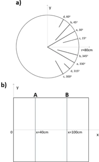
Figure 2. Visualisation of placing measurement probes: a) determining individual probes, b) coordinates of planes A and B.
The effectiveness of drying cylindrical straw bales (with dimensions: diameter 160 cm, length 140 cm) with exhaust gases was measured with a specially prepared recorder equipped with eight measurement probes. They were calibrated by producer on sample of straw with varied humidity. Capacitive relative humidity sensors and temperature sensors with the SHT11 device [15] were installed.
Measurement probes varied in length (80 cm, 60 cm, 40 cm and 20 cm denoted respectively by lowercase “a”, “b”, “c” and “d”), so it is possible to measure humidity and temperature in places with the preset distance from the axis of the straw bale. Figure 2 presents the visualisation of placement of the right probe in the bale during the measurement.
by 40 cm (plane A, x=40) and by 100 cm (plane B, x=100). At first measurements were conducted in plane A, and then in plane B.
Experimental results are presented below. The curves show the change of temperature and humidity during the drying process. The prefix “A” and “B” at each label of the probes means the measurement plane according to Figure 2b, and the prefix “T” and “H” means the measurement of temperature and humidity, respectively.
This article presents the possibilities of drying straw in the modified drying process. After collecting a number of experiences in the straw drying process in the form of bales [16] some modifications of this process have been implemented, which involved the hollowing of a duct along the bale axis with the diameter of 63mm (the duct is marked as no. 3 in Figure 7) and applying the metal plate with the diameter of 1,000 mm to the opposite side of the bale (the plate marked as 4 in Figure 7) from the fitted drying medium. This modification was designed to allow the most radial propagation of the medium and to obtain the uniform temperature and humidity inside the bale in question.
3 Experimental stand
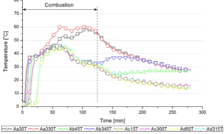
The curves in Figure 3-6 present the change of temperature and humidity for particular regions of the straw bale. “Combustion” – is the period, when the combustion of the insert took place in the form of straw in the biomass boiler. During this period the drying medium was supplied to the bale with the given temperature. After the combustion process the measurements were continued with the blowing air fan turned on. In this case the drying medium was the heated air after passing through the warmed but not operating boiler. As a result the medium had lower temperature comparing to the combustion period. Measurements were carried out in one straw bale with the potentially uniform initial humidity in the given measurement surface between 66-90% through the period of 280 min.
Changing temperature inside the dried straw bale in the A plane is presented in Figure 3. We can observe the rapid increase of temperature in the whole volume of the bale. Then, after approx. 30 min from beginning measurements the rapid temperature increase is reduced. In approx. 70 min of drying the highest temperature is achieved within the bale of about 45 oC. Only the “Aa30T” and “Aa330T” sensors located inside the bale recorded much higher temperatures of approx. 60 oC. After completion of the combustion process, temperature inside the bale started to slowly decrease. The bale layer represented by “Ab45T” sensors maintained a constant temperature after the completion of the combustion process. While the “Ab345T” sensor was characterised by the increase of the temperature from the moment of ending combustion until 170 min of the drying process. The temperature increase could be caused by the heat transfer from the layer from the bale axis to the more external layer described by the “Ab345T” sensor. Then, temperature started to slowly decrease until reaching the final value of 27 oC. The same final temperature has also
been recorded in the location of installing the “Aa30T”, “Aa330T” and “Ab45T” sensors. Table 1 presents the maximal temperatures for the given sensor in the plane obtained during experimental measurements and from CFD modelling described in the next chapter. One can observe a very good fit of the model to the experimental results in plane A. The best fit was achieved for the “Aa30T” sensor, from which 60 oC was achieved. The worst one characterised the “Ad60T” sensor, for which the difference of 6 oC was reached.
Table 1. The maximum temperatures reached for the location of the given sensor in individual planes in the
experimental measurement and the CFD model.
Plane A Plane B
Monitor Point
Experimental CFD model
Experimental CFD model a30T 60 oC 60 oC 63 oC 63 oC a330T 58 oC 60 oC 55 oC 63 oC b45T 45 oC 42 oC 57 oC 60 oC b345T 46 oC 42 oC 60 oC 62 oC c15T 44 oC 40 oC 43 oC 41 oC c300T 43 oC 41 oC 49 oC 44 oC d60T 44 oC 38 oC 40 oC 41 oC d315T 44 oC 39 oC 42 oC 42 oC
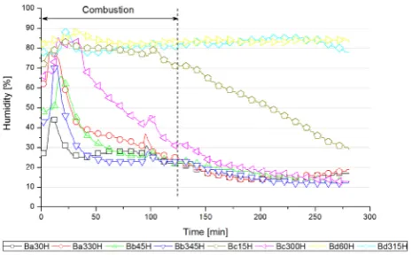
Figure 4 presents the change of humidity inside the bale of straw in plane A. The initial moisture value was approx. 66-90% and fluctuated within these limits to approx. 50 min of the drying process. At this point took place the rapid change of moisture in the place represented by “Aa30H” and “Aa330H” sensors. Until the completion of the combustion process in the boiler, the humidity in these places dropped until reaching 13%. The next layer represented by “Ab45H” and “Ab345H” sensors maintained at the constant level of 70-80% until 110 min of conducting data recording. Then the humidity started declining and reached the final value of 15%-20%, like for the “Aa30H” and “Aa330H” sensors. Humidity of more external layers during the whole drying process maintained at the permanent level. For “Ac15H” and “Ac300H” sensors it was 70-80%, and for “Ad60H” and “Ad315H” sensors 80-90%.
Figure 4. The change of humidity in the straw bale in the plane A.
Figure 5. The change of temperature in the straw bale in the plane B.
Figure 6. The change of humidity in the straw bale in the plane B.
After performing measurements in plane A, which lasted for 280 min, the observation of dynamics of straw bale drying has been started in plane B. Changing temperature inside the bale and straw humidity in plane B has been presented in Figure 5 and Figure 6. At first we observe the rapid increase of temperature in the bale axis layer, until reaching approx. 50-60 oC. Then, the next layers represented by proper sensors started heating later than the similar dynamics is observed in the case of the bale axis. Such heating of the individual layers in the
straw bale is caused by the structure and physical properties of the straw. This is contributed by the dense packing of straw and the low coefficient of heat transfer [17, 18]. After achieving maximal temperatures by sensors representing the given layers in the period of 25-50 min from starting the measurement, the temperature maintained at the similar level until the end of the “Combustion” period. Then, temperatures started slowly dropping until reaching the value of 15-30oC. The highest temperatures and the fastest heating time was achieved by layers closest to the bale axis, and then the more external layers. Temperature distribution in case of plane B was slightly different than in case of plane A. This could be caused by the lower content of humidity or better radial flow of the drying factor caused by the application of the drying process modification, and as a result the higher pressures and better factor penetration occur closer to the place location than in the case of plane A.
Change of humidity during drying in plane B is presented in Figure 6. The initial bale humidity in plane B was between 27-82%. In the initial phase of the drying process the bale humidity rapidly increased, what was caused by the large increase of temperature in these places. After the period of approx. 20 min the humidity started declining. At the end of the “Combustion” process in the 125 min, the humidity for “Ba30H”, “Ba330H”, “Bb45H”, “Bb345H” and “Bc300H” sensors was 22-30%. The “Bc15H” sensor recorded the value of 70%, and “Bd60H” and “Bd315H” sensors 80-85%. Moisture values at the end of the drying process for most sensors remained at the similar level as in the 125 min. Only the “Bc15H” sensor noted a significant decrease and at the end of the observation the humidity was 30%.
4 Numerical method
To perform series of the analyses of the straw dryer, a simple transient simulation of the heat and mass transfer inside the dryer has been performed. Vaporization from the straw bale pores initiates, when its temperature reaches the vaporization temperature of water. Due to this fact, it is reasonable to examine on the early stage of the numerical modelling the process of the heat transfer inside the bale.
Computational grid has been generated in steps - individually for each separated subregions. The subregions were created by division of the spatial geometry (subregions of the domains have been defined as so-called "parts") in ANSYS DesignModeler tool. This approach provides high fraction of the grid elements characterized by satisfying level of the quality. To evaluate mesh quality the "element metrics" coefficient has been used (equal 1 for the best elements and 0 for the worst). The fraction of grid elements of the quality larger than 0.75 is 57.5%. The total number of the elements in the computational grid is equal 525,000.
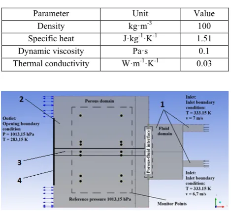
The part of the domain representing the straw bale has been defined as a porous body, characterised by the porosity equal 0.5. Assumed parameters of the straw domain are summarised in the Table 2.
Table 2. Basic properties of the straw bale domain material
Parameter Unit Value
Density kg·m-3 100
Specific heat J·kg-1·K-1 1.51 Dynamic viscosity Pa·s 0.1
Thermal conductivity W·m-1·K-1 0.03
Figure 7. Chosen parameters and boundary conditions of the numerical simulation.
Figure 8. Temperature distribution in the straw bale in the agreed state: a) cross-section, b) longitudinal section.
Gas heating the straw bale has been defined as an continuous fluid, characterized by the thermodynamic properties of air. Set of the boundary conditions has been defined. Values of the parameters, such as temperature and velocity of the inlet air (velocity of inlet air in each air duct was measured using anemometer), ambient pressure and temperature were determined based on the results of the experimental measurement. Detailed information about the preprocessing of the numerical model (boundary conditions and settings) are presented in Figure 7. Moreover, Figure 7 presents the air ducts and a special designed nozzle (1), straw bale (2), hole inside the bale (3) and metal plate (4).
Except the parameters, set of so-called monitor points have been defined (in Figure 7 – marked by dots in the crosses), which allowed to monitor temperature values calculated for the estimated points of location of the sensors used in the experimental tests of the dryer.
The k-epsilon model of turbulence has been implemented for the fluid domain. Such approach is reasonable in case of the fluid flow between hot exhaust gas inlets and the edge of the straw bale. Due to the high velocity of the fluid flow and small distance between the planes, the flow is turbulent. Only phenomena in central region of the straw bale were considered with special attention, so it was unnecessary to create advanced dense grid in regions near to the edges (lack of the dynamic changes of the pressure). Due to this fact, k-epsilon model of turbulence could be applied.
Required residuals level for the solver has been set to 10-5. Advection scheme has been defined as upwind (robust but less accurate than the high resolution mode). In first approach arbitrary chosen time scale were applied. Due to simplicity the time step was set as 1s. Using this time step dynamics of the temperature variation and other experimental parameters were well reflected in the simulation. Total time of the simulation was equal 1,500s (1,500 time steps).This time is sufficient to stabilize the temperature for each monitor points inside the straw bale. Longer simulation gives no essential improvements of the model output.
Figure 8 presents the cross-sections of the simulated solid domain (straw of bale). Colours on the planes correspond to appropriate value of the temperature in the last time step of the simulation, when state (temperature) of the straw bale was stable. The CFD simulation showed a very good temperature distribution around the straw bale perimeter. The highest temperatures were reached in the central part of the bale or in the plane presented in Figure 8a or Figure 8b, what also translates to the lowest humidity content. The further away from the bale axis, the lower the temperature. The same temperature distributions were achieved during experimental measurements.
Temperature distribution in the bale complies with the velocity vectors distribution, what is confirmed by the Figure 9. Relatively high temperature in the region of straw near to the nozzle is result of the turbulent movement of the fluid in the gas domain area.
The performance of modifications helped in the intensity of straw heating near the outlet of the dryer. In addition, the heat use has been improved, what translated into the more uniform heating of the straw bale and limitation of places where the heat was not supplied. After performing the CFD model, next modifications could be suggested, which should rely on optimising the hole inside the straw bale (its diameter, number and placement), a nozzle injecting the drying medium as well as the diameter of the metal plate.
5 Conclusions
The above article presented possibilities for drying straw in the form of bales. Experimental and numerical method was conducted for testing the effectiveness of drying and the transfer of heat and mass in the straw bale with the given boundary conditions. Experimental studies have shown that the internal layers of the bale are heated much faster. Additionally, the achieved temperatures are higher in the central part of the bale. After approx. 5 hours from starting the drying process, the satisfactory humidity of the straw was obtained in the bale axis of approx. 15-20%. Almost homogeneous humidity field was obtained after almost 10 hours of drying. After this time, only the most external layer maintained the humidity at the constant level of about 80%. The results obtained through the experimental and numerical way showed that the current drying process is satisfactory, because the bale heats evenly. The problem occurs for the external layer, where humidity remains at the constant, high level. After
analysing the obtained results, the new, improved drying method was suggested, which will allow the most radial distribution of the drying medium. It will consist of optimising the hole inside the straw bale (its diameter, number and placement), a nozzle injecting the drying medium as well as the diameter of the metal plate. This will allow for more uniform heating of the bale in the whole volume, and thus its much shorter and more effective drying.
Acknowledgments
This work was financially supported by the Dean Grant of Faculty of Energy and Fuels at AGH University of Science and Technology and it was carried out by BioEcoMatic Project within KIC InnoEnergy Programme.
References
1. W. Goryl: Mater Thesis, AGH University of Science and Technology (Kraków, 2012)
2. W. Goryl, A. Gua, Zielona Planeta 112, 16-19 (2014) [In Polish]
3. A. Gua, P. Wajss, W. Goryl, Przegld Elektrotechniczny 5a, 198-203 (2012)
4. M. Dakowski, S. Wickowski, O energetyce dla uytkowników oraz sceptyków (Fundacja Odysseum, Warszawa, 2005) [In Polish]
5. Central Statistical Office of Poland, Procurement and prices of agri. prod. in 2014 (Warszawa, 2015) 6. Central Statistical Office of Poland, Concise statistical yearbook of Poland2015 (Warszawa 2015). 7. W. Goryl, Proceedings of 11th International Conference ENEF, Banska Bystrica (2014)
8. A. Ludwicka, A. Grzybek, Prob. of Agri. Eng., 2, 101-111 (2010) [In Polish]
9. D. Kwaniewski, Agric. Eng., 104, 113-119 (2008) 10. A. Grzybek, Straw – Implementation in Heating, (Wydawnictwo ITP, Falenty, 2012)
11. V. Vladut, M. Chitoiu, A. Danciu, M. Militaru, C. Lehr, Bull. UASVM Agric., 67, 292-300 (2010)
12. S. Kalinauskaite, A. Sakalauskas, E. Sarauskis, A. Jasinskas, Agron. Res., 11(2), 319-328 (2013)
13. H. Li, Q. Chen, X. Zhang, K. N. Finney, V. N. Sharifi, Appl. Therm. Eng., 35, 71-80 (2012)
14. K. Sornek, M. Szubel, W. Goryl, E. Boek, M. Filipowicz, Przem. Chem., 12(93), 2071-2076 (2012) 15. http://www.sensirion.com/fileadmin/user_upload/ customers/sensirion/Dokumente/Humidity/Sensirion_Hu midity_SHT1x_Datasheet_V5.pdf [access: 10 June 2015] 16. W. Goryl, Proceedings of 2nd International Conference RENEWABLE ENERGY SOURCES engineering, technology, innovations - scientific conference, Krynica (2015)
17. A. Thomson, P. Walker, Constr. Build. Mater., 68, 135-141 (2014)