Droop Controlled Technique for Voltage
Source Inverters in Mini-grid System by using
PI Controller
(An Autonomous mode)
Amit S. Borole1, Kamlesh K. Chauhan2
Assistant Professor, Department of Electrical Engineering, Government College of Engineering, Jalgaon, Maharashtra,
India1
Assistant Professor, Department of Instrumentation Engineering, Government College of Engineering, Jalgaon,
Maharashtra, India2
ABSTRACT: Over the years, power converters have found wideapplication in grid interfaced systems, including distributed power generation with renewable energy sources. In distributed energy systems like solar, hydro or any diesel generation where the output of the system is DC and is expected to be converted in AC, an inverter is used. There are various modes to have a controlled output of inverter. This output is to be controlled such that there should be balanced supply when inverters are connected in parallel.
The paper consists of three phase Voltage Source Inverter control scheme which is called as Proportional controller. In PI control, the stationary reference frame is used to transfer the feedback quantities from load side to source side. In this process, the decoupling of d and q components arises which is little complex. The PI controller is adopted in the most familiar dqo reference frame. The three phase system is simulated in the matlab-simulink environment with the controller and experimental results are given to prove the correctness and feasibility of the system.
The droop control technique is all about sharing of the Active and Reactive powers between parallel connected inverters connected in Mini-Grid system. The sharing of power will be based on the ratings of the inverter when they are subjected to any change in load. This technique is important because, there is no external link is required between the inverters to share the load.
KEYWORDS: PI controller; d- q reference frame; alpha betareference frame; reference tracking; Droop control; three loop control; wireless communication, mini-grid;
I.INTRODUCTION
In order to control the renewable energy sources more effectively and fulfill power quality requirement, micro-grid concept is proposed more recently. A micro-grid is a cluster of RES and loads, which can operate in both grid-connected mode and islanded mode. All the renewable energy sources are parallel connected to an ac common bus through inverters or ac-to-ac converters. The key functional element of an AC Micro-Grid system is a Voltage Source Inverter (VSI). The different Renewable Energy Sources (RES) within the Micro-Grid system can operate independently or interconnected to a common DC link which supplies constant input to the VSI. These systems are to be properly controlled in order to provide the reliable power system to the utility network [2-4].
This paper focuses on a control strategy that is used for the operation of a parallel inverters based micro-grid. First, the power flow in a network system is investigated, based on which the droop control method for micro-grid is presented. Furthermore, inverter control techniques are discussed and combined with the droop method for proper power sharing. Droop control is a concept which is done for active and reactive power sharing between the parallel inverters. For droop control technique, there is a need of at least two parallel connected inverters [5]. As the main objective is to observe power sharing between the two inverters, droop control technique is mainly used for minigrid systems where main grid in islanded. This control method is used for the regulation of the voltage and the frequency on AC minigrids, fed by voltage source inverters. In order to avoid a complex communication network for the synchronization of the various VSI on a minigrid, a conventional method called Droop Control is used.
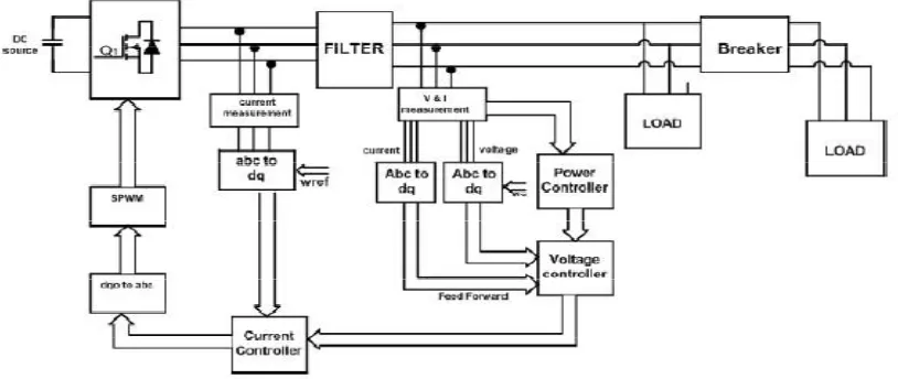
Figure 1. Block diagram of droop controlled inverters.
Figure 1 shows the block diagram of droop controlled parallel connected voltage source inverters.
The parallel connected voltage source inverters may have following problems to face[1,6]:-
• To maintain amplitude and frequency of the voltage in a micro-grid within a normal range when operating in autonomous mode;
• To share adequate active power and reactive power from energy sources to the loads when operating in autonomous mode;
• To perform optimal power exchange between micro-grid and the main power grid when operating in grid-connected mode;
• To ensure a smooth transfer between inverter and grid in autonomous mode and grid connected mode.
value. It is very important to have a very reliable power supply and for that, the system needs, a good controller. This can be achieved by PI controller. The general conclusion is that, many of the controllers for this particular system are either overburdened because of the complex network or they are very difficult to implement. Hence the controller selection and its implementation becomes very important [5].
The simple PI controller is used for controlling the inverter output. The main advantage of the PI controller is that there will be no remaining control error after a set-point change or a process disturbance. A disadvantage of PI controller is that there is a tendency for oscillations. PI control is used when no steady-state error is desired [3]. There is a use of synchronous frame in PI control, where abcquantities are converted to dqo quantities and then error signal is fed to the PI controller.
II. SYSTEM DESCRIPTION
The micro-grid can be connected either in grid connected mode or an autonomous (islanded) mode. Normally the micro sources act as constant power sources, when they are operated
in grid connected mode, which means that they are controlled to inject the demanded power in to the network. In autonomous mode the micro sources are controlled to supply all the power needed by the local loads while maintaining the voltage and frequency within the allowed limits. The system shown in Fig. 1 is the parallel operation of two inverters when they are operated in autonomous mode. It consist of filter and inverter block whose specifications are given in the table no 1. The controller blocks given in Fig. 1 are implemented by PI controller. This controller is analyzed and implemented in following sections.
III. CONTROLLER
This paper reviews the control schemes for controlling the droop controlled VSI. The current controller can have a significant effect on the quality of the current supplied to the load by the inverter, and therefore it is important that the controller provides a high quality sinusoidal output with minimal distortion to avoid harmonics. The PI controller development is explained in detail below.
A. PI CONTROLLER
For three phase systems, synchronous frame simple PI controller can be used as shown in Figure 2. The main advantage of the PI controller is that there will be no remaining control error after a set-point change or a process disturbance. But the main problem with PI controller is that, there will be steady state error for three phase system, whereas, for single phase systems, PI controller is the most effective and easier to implement. Figure 2 shows the PI controller implementation block diagram. PI controller requires abc to dqo reference transformation. As shown in figure 2, the voltage after the filter is sensed and phase lock loop is used to extract systems angular frequency from it.
Figure 2. Block diagram of droop control technique using PI controller
sensed before the filter and the reference signal generated by voltage sensed after the filter. The reference generator block shown in Fig. 2 is implemented on the basis of (5) and (6). This block takesoutput voltage or grid voltage in dq0 reference frame (Vod and Voq), as input signals. Thus it generates reference currentsignals (idref and iqref) which are
compared with actual current signals.
The active power (P) and reactive power (Q) supplied to grid can be given in synchronous reference frame as
P = 1.5(Vod id + Voqiq) (1)
Q = 1.5(Vodiq + Voq id) (2)
Where the Vod, Voq, id, iq are the voltages and currents after the filter in dqo reference frame and P, Q are the
active and reactive power respectively.
Assumed Voq = 0, and hence (1) and (2) can be written as
P = 1.5(Vod id ) (3)
Q = 1.5(Vodiq ) (4)
From above equations, id and iq can be extracted as-
id = 2P / 3 Vod (5)
iq = 2Q / 3 Vod (6)
These current signals are compared with actual and given to the PI controller. As PI controller requires feed forward path to improve reference tracking, grid voltage is fed to it. Then these signals are again transformed to abc frame and from SPWM, it is fed to the inverter switches [7].
B. REFERENCE QUANTITIES:
The reference quantities required for the simulation of droop controlled parallel inverters are reference frequency and reference voltage according to the demand or load. These signals can be extracted from load side of filter. For frequency, an angular frequency can be extracted from active power and voltage can be extracted from reactive power asstated below.
Active Power (P) α Suppy Frequency (f)
(7)
mp= -
∆
(8)
mp= -(ωref-ωactual) / P
(9)
ωref = ωactual - mpP
(10)
Reactive Power (Q) α Voltage (V)
(11)
nq=
-∆
(12)
nq= - (Vref- Vactual) / Q
(13)
Vref = Vactual – nqQ
(14)
would appear if the impedance between the generators and a common load were not the same.
IV. SIMULATION RESULTS
The three phase inverters are connected in parallel as explained in earlier section and are controlled by PI controller in droop control mode. The simulations are carried out for various load conditions and the system is thus examined at the change of load. The DC supply is fed to the inverter as a distributed generation source. The LC filter is used to eliminate the harmonics after the inverter. The quasi shaped inverter output is thus converted to sinusoidal wave. The filter output is fed to the load. The parameter values used in the simulation are given in the table no 1.
The droop coefficients are need to be specified in analysis. These coefficients are required to extract reference quantities as given in equations 9-14. These coefficient values are given in Table No.2.
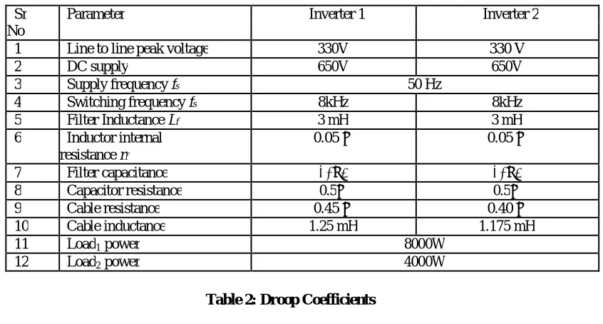
Table 1: System parameters
Sr Parameter Inverter 1 Inverter 2
No
1 Line to line peak voltage 330V 330 V
2 DC supply 650V 650V
3 Supply frequency fs 50 Hz
4 Switching frequency fs 8kHz 8kHz
5 Filter Inductance Lf 3 mH 3 mH
6 Inductor internal 0.05 Ω 0.05 Ω
resistance rf
7 Filter capacitance 30μF 30μF
8 Capacitor resistance 0.5Ω 0.5Ω
9 Cable resistance 0.45 Ω 0.40 Ω
10 Cable inductance 1.25 mH 1.175 mH
11 Load1 power 8000W
12 Load2 power 4000W
Table 2: Droop Coefficients
mp nq
Inverter 1 4.5
e
-5 0.0013Inverter 2 9
e
-5 0.0028Figure 5. Three phase load voltage using PI controller
Figure 6. Three phase load current using PI controller
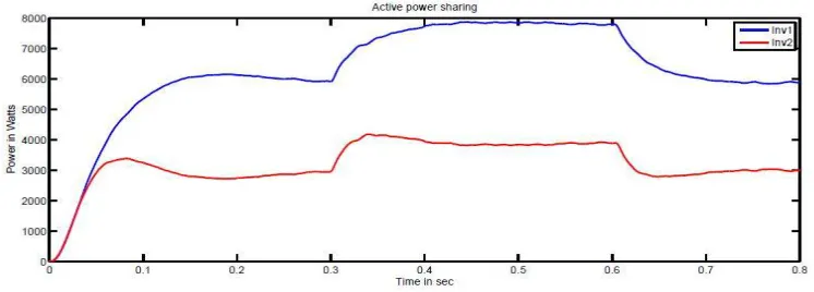
From Fig. 7 and Fig. 8, it can be seen that, during transient PI controller takes little more time for settling, as it takes nearly 0.06 sec to reach to the steady state. These figures are the waveforms of active and reactive powers supplied by both the inverters when the system is subjected to a change in load from 0.3sec to 0.6sec.
Figure 8. Reactive power supplied by both the inverters to the load
V. REFERENCE TRACKING BY PI CONTROLLER
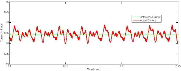
From the Simulation results, effectiveness of PI controller can be enhanced as its reference tracking system is given in Figure 9. The reference current is set at 14.5 Amps and actual quantity tries to achieve it for each feedback signal of PI controller.
Figure 9. Tracking reference quantities with actual for PI controller
VI. CONCLUSION
In this paper, the main attempt is made of droop controlling of three phase parallel connected inverters. For this, PI controller is used to synchronize load and the system. The system is examined in matlabsimulink and hence the results are depicted in figures 5-9.
Droop control technique is the active and reactive power sharing between the parallel inverters according to the demand of load. This is excellently achieved in the above system and can be analyzed in Figure 7 and 8.
REFERENCES
[1] J. Vasquez, J. Guerrero, M. Savaghebi, J. Eloy-Garcia, and R. Teodorescu, “Modeling, analysis, and design of stationary-reference-rame droop-controlled parallel three-phase voltage source inverters,” Industrial Electronics, IEEE Transactions on, vol. 60, no. 4, pp.1271–1280, April 2013.
[2] N. Pogaku, M. Prodanovic, and T. Green, “Modeling, analysis and testing of autonomous operation of an inverter-basedmicrogrid,” Power Electronics, IEEE Transactions on, vol. 22, no. 2, pp. 613–625, March 2007.
[3] J. Quesada, J. Sainz, R. Sebastian, and M. Castro, “Decoupled droop control techniques for inverters in low-voltage ac microgrids,” pp. 1– 6, Feb 2014.
[4] A. Nachiappan, K. Sundararajan, and V. Malarselvam, “Current controlled voltage source inverter using hysteresis controller and pi controller,” pp. 1–6, Jan 2012.
[5] K. De Brabandere, B. Bolsens, J. Van den Keybus, A. Woyte, J. Driesen, R. Belmans, and K. Leuven, “A voltage and frequency droop control method for parallel inverters,” vol. 4, pp. 2501–2507 Vol.4, 2004.
[6] J. Hu, J. Zhu, D. Dorrell, and J. Guerrero, “Virtual flux droop method 2014;a new control strategy of inverters in microgrids,” Power Electronics, IEEE Transactions on, vol. 29, no. 9, pp. 4704–4711, Sept 2014.