Interval Type-2 Fuzzy Logic Controller for
DC-DC Converter
R. Saranya
Assistant Professor, Dept. of Electrical and Electronics Engineering, Sri Krishna College of Engineering &
Technology, Coimbatore, India
ABSTRACT: In this paper an Interval Type2 Fuzzy Logic (IT2FL) controller is proposed for the control of DC-DC converters to attain a good output voltage regulation and dynamic response. The buck and boost type DC-DC converters are considered for the implementation of the IT2FL controller. To study the effects on the system performance, the conventional PI and type-1 fuzzy controller are designed and compared with interval type-2 fuzzy controller. Design of PI control is based on the frequency response of the DC-DC converter. Design of IT2FL controller is based on heuristic knowledge of converter behavior and tuning requires some expertise to minimize unproductive trail and errors. The setting time, the overshoot and the steady state error of the converter are used as the performance criteria for the evaluation of the controller performance. From the comparison, it is inferred that IT2FL controller will give better result than other controllers.
KEYWORDS: DC–DC converter, PI controller, Type-1 Fuzzy Logic (T1FL) controller, Interval Type-2 Fuzzy Logic(IT2FL) controller, GFS toolbox.
I.INTRODUCTION
Type-1 fuzzy logic (T1FL) controllers have been successfully used in numerous applications many of which are too complex to be analyzed using conventional mathematical techniques for years. In design of T1FL controllers, the experience and knowledge of human experts are needed to determine parameters associated with the rule base and membership function [1]. Type-1 Fuzzy Systems is also called as conventional fuzzy systems. Type-2 system is capable of handling uncertainties involved with type-1 fuzzy systems. Zadeh [2] introduced type-2 and higher-types
fuzzy systems in 1975 to eliminate the paradox of T1FL systems which can be formulated as the problem that the
membership grades are themselves precise real numbers. Type-2 and higher-types systems are an extension of T1FL systems. Type-1 fuzzy sets are not able to directly model such uncertainties because their membership functions are totally crisp. On the other hand, type-2 fuzzy sets are able to model such uncertainties because their membership
functions are themselves fuzzy. Membership functions of type-1 fuzzy sets
are two-dimensional, whereas membership functions of type-2 sets are three-dimensional. The new
third-dimension of type-2 fuzzy sets that provides additional degrees of freedom that make it possible to directly model uncertainties. Similar to T1FL systems, Type-2 Fuzzy Logic (T2FL) systems comprise fuzzifier, rule base, inference engine and output processor.
office equipment, spacecraft power systems, laptop computers, and telecommunications equipment, as well as DC motor drives [4]. Several control techniques for DC–DC converters have been reported in the literature, such as linear based control techniques, sliding mode control technique, and fuzzy logic control technique. Although the structure and design of linear based control techniques are simple, their performance usually depends on the working conditions of the controlled system. Sliding mode control technique needs a system model to be designed. One of the most important problems in design of this controller is control chattering [5]. Traditional fuzzy techniques provide for the output voltage regulation against input voltage However, the performance of this controller depends on the experience and knowledge of human experts. In general, trial-and-error tuning procedure is used to adjust parameters of the rule base and membership sets [6]. This means that these parameters will be change from one expert to another expert. The controlled system performance may be undesirably affected from these uncertainty conditions. Thus, a type-2 fuzzy controller will be highly suitable to tackle the uncertainty which occurs in traditional fuzzy logic controllers. Karnik and Mendel [7], [8] established a complete Type-2 FLS theory to handle uncertainties in FLS parameters.
In this work, an IT2FL controller is proposed for the control of the buck and boost DC–DC converters to achieve a good output voltage regulation and dynamic response against input voltage. To analyze the effects on the system performance of IT2FL controller, the converters are also controlled using the PI and traditional fuzzy controller.
II. MATHEMATICAL MODELLING OF DC–DC CONVERTER
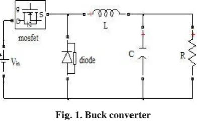
Two basic converter topologies known as a buck converter and a boost converter are used to determine the effect of type-2 fuzzy logic controller on the performance of DC–DC converters. A buck converter and a boost converter is basically composed of a power switch which transforms the energy of a DC voltage source , a diode D, a LC filter which reduce the high frequency components, and a resistance R which is used as a load. The circuit diagram of buck
converter and boost converter is shown in Figure 1 and Figure 2 Vin,Vout are the input and output voltage of both
converters. In steady state operation [9], both converters have two operating mode.
Fig. 1. Buck converter
In the first operating mode of the buck converter, a positive voltage across the inductor occurs while the mosfet is turned on and the diode becomes reverse biased. This voltage causes a linear increase in the inductor current. In mode 2 operations, when the mosfet is turned off and the diode is forward biased, the inductor current decreases due to a negative voltage across the inductor. The differential equations describing the dynamics of the buck converter is obtained through the direct application of Kirchoff‘s current and Kirchoff‘s voltage laws for each one of the possible circuit topologies arising from both operating modes of the buck converter.
LdIL V D V
dt in out
(1)
CdV i V
out out
dt R
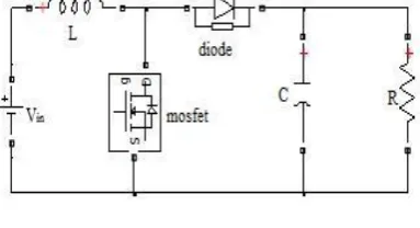
In the first operating mode of the boost converter, when the mosfet is turned on, it conducts the inductor current and the diode becomes reverse biased. This result in the input voltage of the converter across the inductor. This voltage causes a linear increase in the inductor current. In the second mode, when the mosfet is turned off and the diode is forward biased, the inductor current will continue to fall as long as the output voltage is greater than the input voltage.
Fig. 2. Boost Converter
In a similar way, the differential equations describing boost converter can be obtained by applying Kirchoff‘s laws to the circuit topologies arising from both operating modes of the converter.
dI L L V
in (1 D)V out dt
dV
V out C out (1 D)I
L
dt R
(3)
(4)
Where D is duty cycle,
I L
is the inductor current.
By using the design parameters, LC values can be formulated. The switching frequency of buck and boost converter is 2 KHz. The input voltage of both the converter is 24V. The output power is 50W for both the converters. Below table 1 shows the circuit parameters of both converters.
PARAMETERS BUCK CONVERTER BOOST CONVERTER
OUTPUT VOLTAGE 12V 54V
DUTY CYCLE 0.5 0.55
CAPACITANCE 104µF 500µF
INDUCTANCE 60Mh 67mH
LOAD RESISTANCE 2.83Ω 48Ω
a. Small Signal Modeling
The averaged model of the buck converter in equations 1 and 2 are linear but does not consider the time varying nature of the supply voltage and the duty cycle [10]. So, in order to make the small signal analysis, the variables Vin, D and output voltage Vout are assumed to be varying over the steady state values with small amount of perturbations. Control voltage gain transfer function,
Vout Vin
d s2LC s(L R)1
(5)
Similarly the boost converter‗s transfer function can be derived. Control‐to‐output transfer function
Vout (S ) (1 D)Vout LI LS
D(S )
(LC) 2 L
S (1 D) 2 R
(6)
III. DESIGN OF THE PI CONTROLLER
PI controllers are implemented in numerous applications by computer algorithms. This means that the controller inputs are measured at certain sampling rates. Thus, it is important that controller equations are defined as discrete time before making application of the controlled system. In the first step of the design procedure of the discrete PI controller, the equation of a conventional PI controller defined in the time domain is needed. In general, the transfer function of a conventional PI controller can be represented by
Transfer function =
K
i
K
Ps
(7)Where,
K
i: Integral gain,K
P: Proportional gain.
The coefficients Kp and Ki of the PI controller can be adjusted using Ziegler–Nichols method and the model based
methods such as frequency response method, root locus and pole assignment design methods. In this paper, PID tuner is used to adjust the coefficients of the PI controller and it requires a system model and control parameters are designed
from the plant step response. From PID tuner, the coefficients Kp and Ki of the controllers are obtained as 0.017186,
IV. DESIGN OF THE T1FL CONTROLLER
Block diagram of the T1FL controller used for the control of the DC–DC converters is shown in Figure 3.
Fig. 3. Block diagram of T1FL
The T1FL controller is divided into four sections: fuzzifier, rule base, inference engine, and defuzzifier. During the fuzzification process, all input data are classified into suitable linguistic values or sets. According to knowledge of the control rules and the linguistic variable definition, a fuzzy control action is derived in the inference section. Then, a crisp control action is obtained by converting the inferred fuzzy control action in the defuzzifier section. The output of the fuzzy controller is the change in the reference waveform which determines the change in the duty cycle rate. The T1FL controller has two inputs: error (e) and the change in the error (Δe). Both inputs are created by using the output voltage of converters. The error for the output voltage can be given as follow.
e
(
k
)
V
ref
V
out
Where Vref : reference output voltage and error is expressed as follow.
Vout
(13)
the sensed output voltage at the kth sampling time. The change in the
e(k) e(k) e(k 1) (14)
The universe of the output error, the change in the output error and the change in duty cycle are divided into seven fuzzy sets as given in Figure 4.
Fig. 4. Membership function of T1FL
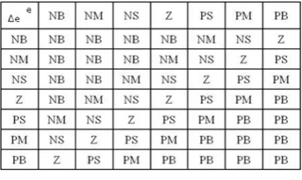
However, the control rules for most applications are usually developed using ―trial and error‖. In this study, the fuzzy control rules for the T1FL controller are obtained from the analysis of the system behaviour. The derivation of the fuzzy control rules is based on the following criteria: 1) when the output voltage error and the change in the output voltage are very big (PB or NB), the corrective response given by the controller must be robust (duty cycle close to zero or one) in order to have the dynamic response as fast as possible. 2) When the output voltage error and the change in the output voltage approach zero (NS or PS), the controller must be forced to give a lower response (a small change in duty cycle). 3) when the output voltage error and the change in the output voltage is reached zero or is very close to this point, the controller response must kept constant (zero change in duty cycle) so as to prevent overshoot. Forty nine
fuzzy control rules derived from these criteria are given in Table 2. After selecting the active rules associated with the
input values, the fuzzy inference method whose task is the inference result of each rule is determined. Although there have been several fuzzy inference method such as Mamdani, Larsen, and Takagi_Sugeno fuzzy implications, Mamdani‘s MIN implication is commonly used in most application studies.
Table 2 Rule base
In this paper Mamdani FIS is used. Finally, the defuzzification method obtained crisp result from linguistic inference result is selected. The most popular way to perform the defuzzification operation is through the centroid method, where the output of controller can be computed by a logical sum of the inference results of the active control rules. The centroid method is also called as centre of gravity, centre of mass or centre of area. It is the most commonly used defuzzification method. The defuzzified output is
N f i .w i
U i 1
fc
N i
w
i 1
V. DESIGN OF THE IT2FL CONTROLLER
Figure 5 shows the schematic diagram of an IT2FL controller for DC–DC converters.
Fig. 5. Block diagram of IT2FL
The controller mainly consists of five sections which are fuzzifier, rule base, inference engine, type-reducer and defuzzifier. In the IT2FL controller, as in the T1FL controller, the crisp inputs are first fuzzified into input fuzzy sets which then activate the inference engine and the rule base to produce output type-2 fuzzy sets. The type-2 fuzzy outputs of the inference engine are then processed by the type-reducer which combines the output sets and then performs a centroid calculation, which leads to type-1 fuzzy sets called type-reduced sets [11]. Then, the defuzzifier defuzzifies the type-reduced type-1 fuzzy outputs to produce crisp outputs that are used to generate PWM waveform. In interval type-2 fuzzy sets, the secondary membership function is either zero or one. As in the T1FL controller, the labels of type-2 fuzzy sets are assigned with Negative Big (NB), Negative Small (NS), Zero (Z), Positive Small (PS) and Positive Big (PB), respectively. In this paper a nonsingleton fuzzifier Output membership sets used. The IT2FL system has been designed by using GFS toolbox. Generalized Fuzzy Systems (GFS) is Graphical User Interface tool developed for visualizing fuzzification using almost all type of fuzzy sets. The IT2FS membership function can be formed from the type-1 fuzzy set. The membership function obtained from type-1 fuzzy sets can be used here. The type-1 fuzzy set is treated here as Principal Membership Function (PMF) and depending upon the uncertainty due to noise FOU may be specified to get Lower Membership Function (LMF) and Upper Membership Function (UMF). In the IT2FL controller, the rules remain the same as in Type-1 FL controller. The method of defuzzification for this controller is centroid [12].
VI. SIMULATION RESULTS
In order to analysis the effect on the performance of the DC–DC converters of the proposed IT2FL controller, DC– DC converters have been controlled using not only IT2FL controller but also PI controller and T1FL controller. The buck and boost converter can be analysed by using the delay time, rise time, settling time and peak overshoot and steady state error of the converter. The table 3 shows the comparison of closed loop control of buck converter. Table 4 shows the steady state deviation of buck converter for both open loop and closed loop control.
Table 3 Comparison of closed loop control of buck converter
TYPE OF DELAY TIME PEAK OVER- SETTLING TIME
RISE TIME (Ts) SHOOT RATIO
CONTROL (TP) (TS)
(%)
PI 0.0276S 0.53mS 6.59 0.651
T1FL 6.11mS 0.46mS 0.03 0.015
IT2FL 5.91mS 0.41mS 0.02 0.01
Table 4 Deviation in voltages for open loop and closed loop control for buck converter
TYPE OF INPUT REFERENCE OUTPUT VOLTAGE STEADY STATE
VOLTAGE VOLTAGE
CONTROL (V) ERROR (%)
(V) (V)
WITHOUT
24 12 11.4 5
CONTROLLER
PI 24 12 11.54 3.8
T1FC 24 12 11.55 3.7
IT2FC 24 12 11.98 0.16
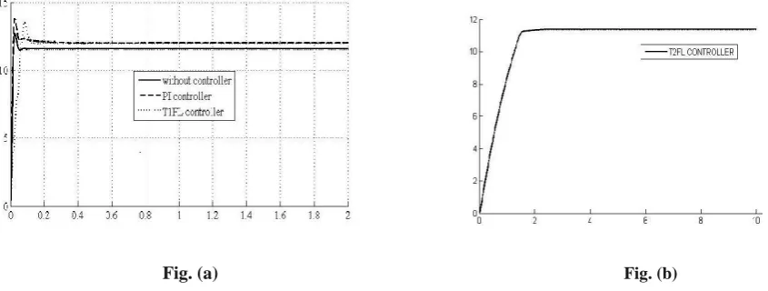
From these results, it can be seen that the IT2FL controlled buck converter give better performance than both the PI controlled buck converter and T1FL controlled buck converter.
Fig. (a) Fig. (b)
Fig. 7. (a) Simulated result of buck converter ( b) Simulated result of T2FL controlled buck converter
It is obvious from the waveform; the IT2FL controller will give good results.
Table 5 Comparison of closed loop control of boost converter
TYPE OF RISE TIME DELAY TIME PEAK OVER- SETTLING
CONTROL (TS) (TP) SHOOT RATIO (%) TIME (TS)
PI 0.028S 2.00mS 11.1 0.135S
T1FC 0.014S 1.66mS 0.76 0.032S
IT2FC 0.012S 1.34mS 0.5 0.020S
The table 5 shows the comparison of closed loop control of boost converter and table 6 shows the steady state deviation of buck converter for both open loop and closed loop control.
Table 6 Deviation in voltages for open loop and closed loop control for boost converter
TYPE OF INPUT REFERENCE OUTPUT VOLTAGE STEADY STATE
CONTROL VOLTAGE (V) VOLTAGE (V) (V) ERROR (%)
OPEN LOOP 24 54 52.29 3.2
PI 24 54 53.44 0.9
T1FL 24 54 53.33 1.2
IT2FL 24 54 53.56 0.7
From these results, it is observed that the IT2FL controlled boost converter give better performance than both the PI controlled boost converter and T1FL controlled boost converter.
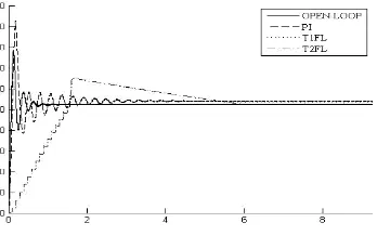
Fig. 9 Simulated result of boost converter
Figure 9 shows the simulation result of the boost converter. It is clear from the waveform; the IT2FL controller will give good results. Thus, the IT2FL controller design method is highly appropriate to apply to DC–DC converters, compared with the PI controller design and T1FL controller design.
VII. CONCLUSION
performances, the settling time, the peak overshoot, steady-state error of the converter has been determined. Simulation results showed that T1FL controller used for the control of the both DC–DC converters had a better performance than the PI controller. When compared with T1FL controller and IT2FL controller, it was shown that the IT2FL controller provided a better performance in the control of the converters because the IT2FL controller was able to handle uncertainties in rules and parameters of input membership functions occurring T1FL controller. In conclusion, the simulation result established that the IT2FL controller was more suitable for application to DC–DC converters than both the PI controller and T1FL controller.
REFERENCES
[1] Lee, C. C. (1990). Fuzzy logic in control systems: Fuzzy logic con-troller-part I/II. IEEE Transactionson Systems, Man and Cyber- netics, 20(2), 404–435.
[2] Zadeh, L.A, The concept of a linguistic variable and its application to approximate reasoning, part 1, 2 and 3. Information Sciences, 1975, 8: 199-249, 8: 301-357, 9:43-80.
[3] Karnik, N. N., Mendel, J. M., & Liang, Q. (1999). Type-2 fuzzy logic systems. IEEE Transactions onFuzzy Systems, 7(6), 643–658.
[4] Wu, K. C. (2006). Switch-mode power converters: Design and analy-sis. London: Elsevier Academic Press.
[5] Wan, K., Liao, J., & Ferdowsi, M. (2007). Control methods in DC–DC power conversion—A comparative study. IEEE Power Electronics Specialists Conference (pp. 921–926).
[6] Gupta, T., Boudreaux, R. R., Nelms, R. M., & Hung, J. Y. (1997). Im ple-mentation of a fuzzy controller for DC–DC converters using an inexpensive 8-b microcontroller. IEEE Transaction on IndustrialElectronics, 44(5), 661–669.
[7] J. M. Mendel, Uncertainty Rule Based Fuzzy Logic Systems; introduction and New Directions. Upper Saddle River, Nj: Prentice-Hall (2001).
[8] Q. Liang and J. M. Mendel, ―Interval Type-2 Fuzzy Logic Systems: theory and design‖. IEEETransactions on Fuzzy Systems, October 2000.
[9] Muhammad, R. (2001). Power electronics handbook, Canada: Academic CRC press.
[10] R. W. Erickson and D. Maksimovic, ―Fundamental of Power Electronics, ‖ 2nd ed. Norwell, MA:Kluwer, 2001.