ISSN (Online) : 2319 - 8753
ISSN (Print) : 2347 - 6710
I
nternationalJ
ournal ofI
nnovativeR
esearch inS
cience,E
ngineering andT
echnologyAn ISO 3297: 2007 Certified Organization, Volume 2, Special Issue 1, December 2013
Proceedings of International Conference on Energy and Environment-2013 (ICEE 2013)
On 12th to 14th December Organized by
Department of Civil Engineering and Mechanical Engineering of Rajiv Gandhi Institute of Technology, Kottayam, Kerala, India
CFD ANALYSIS OF A FLAME DEFLECTOR
WITH WATER COOLING FOR A
SEMICRYOGENIC ENGINE TEST FACILITY
Khalid Rashid, J.C.Pisharady, P.Balachandran
Liquid Propulsion Systems Centre/ISRO, Valiamala, Thiruvananthapuram- 695547, Kerala,India Liquid Propulsion Systems Centre/ISRO, Valiamala, Thiruvananthapuram- 695547, Kerala,India Liquid Propulsion Systems Centre/ISRO, Valiamala, Thiruvananthapuram- 695547, Kerala,India
ABSTRACT
A preliminary CFD analysis is carried out for the flow and heat transfer in a typical deflector plate of a semicryogenic integrated engine test facility using the multi-purpose CFD++ code. Initially, a dry pit without water cooling is analysed followed by a water cooled pit and the salient features of the flow and heat transfer are brought out.
The inner gas side wall temperatures are also obtained from the analysis and it is observed that considerable reduction in temperature is possible by injecting water from the deflector plate surface into the plume. A series of predictions are required further for various configurations, water flow rates and arrangement of cooling holes to arrive at the optimum configuration of the deflector pit and amount of minimum water flowrate for cooling the deflector pit to limit the gas side wall temperatures within the permissible limits to adopt the scheme for actual engine testing.
NOMENCLATURE
X=Distance along the circumferential direction of the nozzle axis Y= Distance along the nozzle axis downstream of nozzle exit Z=Distance perpendicular to the nozzle axis
1. INTRODUCTION
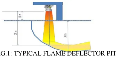
test is protecting the deflector from the harsh thermal environments generated by plume impingement [2]. By controlled deflection of the stream, the deflector dissipates the energy into the surroundings. In several existing facilities worldwide, the hot gas from the engine is cooled by injecting water into the hot gas before it impinges on the flame deflector, so as to keep the flame deflector temperature below the allowable limit of the material [3]. Since the conditions of exhaust gases of high thrust engines are much adverse in terms of its temperature, pressure and mass flow rate, it is mandatory to go for a cooled flame deflector instead of the dry pits to save money and time as well as to reduce technical complexities associated with the construction of the flame deflector and test stand foundation. A schematic of a typical deflector pit configuration for which the present study is conducted is shown in Fig.1.
FIG.1: TYPICAL FLAME DEFLECTOR PIT
Owing to the symmetry of the problem with respect to Z=0, only one half of the domain is considered. The lower portion of the domain consists of the horizontal planar base and the wall-pit. The left, top and right boundaries are inflow/outflow boundaries.
The plume enters the domain through the nozzle exit plane boundary (whose centre is located at Y = 10.0 m) and impinges upon the wall pit. The plume, which is referred to as ‘product’ in this analysis, consists of combustion products of Kerosene and LOX at a mixture ratio of 2.65. The molecular weight
and the ratio of specific heats (γ) for the ‘product’ plume when it enters the domain are given to be 25.825
and 1.2010 respectively. The transport properties (viscosity and thermal conductivity) are taken that of combustion gases. The plume enters at a static pressure of 0.50093 bar, a temperature of 1856.83 K and a velocity of 3320.6086 m/s in the –Y-direction. Here gravity acts in the –Y-direction and is only considered in the interaction of the liquid phase and the gaseous phase (in the EDP momentum equations). The ambient conditions in the domain are at P = 1 bar and T = 300 K. Water is injected through the small holes located on the wall-pit and interacts with the plume and undergoes evaporation.
The objective of the present analysis is to study the cooling of the wall-pit due to the water injection and this paper presents two cases. In the first case, the simulation does not include injection of water through the holes in the wall-pit (‘water-off’ case). In the second case, the simulation includes injection of water through the holes with a total mass flow rate of 370 kg/s and a temperature of 300 K
(‘water-on’ case).
2. MESH GENERATION
FIG. 2: MIME GUI MESH GENERATED ALONG WITH THE DENSITY REGIONS AND FAMILIES
was set to 3.0 m. The family mesh sizes, relative to the global mesh size, range from 0.00025 (‘holes’ family) to 0.25 for the large boundaries. Two density-cylinders were applied. The first one covers the nozzle-exit boundary through which ‘product’ plume enters the domain and extends a little distance downwards in the direction of flow. The relative mesh size in this region is 0.05. The second density-cylinder extends from the nozzle all the way up to the wall-pit where the ‘product’ gas impinges upon the surface. This region is assigned a relative mesh size of 0.1. An XYZ-aligned density box is applied in the X-direction from the wall-pit region where the ‘product’ plume impinges and it extends all the way to the exit boundary. This region has a relative mesh size of 0.1. An arbitrarily oriented density box is applied on the wall-pit region where the product plume impinges and this region has a relative mesh size of 0.05. Prism-layers are applied on all the wall boundaries as well as on the ‘holes’ family. The prism layer growth is geometric and the total number of layers is set to 12. The first layer thickness (3.0e-04m) is chosen so as to ensure that the wall y+ < 30. It should be noted that a finer mesh is usually required if exact heat transfer rates need to be calculated in the problem. This was not a requirement here and thus a mesh suitable for wall-functions was used for the simulations. The mesh consists of about 3.61 million cells. Fig. 2 shows a view of the surface mesh on the MIME GUI along with the density regions described above.
3. SIMULATION METHODOLOGY
FIG.3: INPUT PARAMETRS & BOUNDARY CONDITIONS USED
The density based algorithm is used for solving the governing Compressible RG Navier Stokes equations of the combustion gases flow and the water (steam) flow. The 2 equation Realisable k-€ model is used for modelling the turbulent flow. The gas properties variations are taken as polynomial. The computations are run in a DELL T7500, 8 core, 48 GB workstation using CFD++ version 12.5
4. RESULTS & DISCUSSIONS
4.1. Analysis Results for Water-off case (without water cooling)
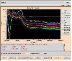
FIG. 4: RESIDUALS VS NO. OF ITERATIONS FIG. 5: PRESSURE (SYMMETRY PLANE)
FIG. 6: TEMPERATURE (SYMMETRY PLANE) FIG.7: VELOCITY ALONG X-DIRECTION
Fig. 5 shows the pressure distribution along the symmetry plane. The pressure contours show
significant variation along the vertical region dominated by the flow of ‘product’ gas through the nozzle.
Fig. 6 shows the temperature distribution along the same symmetry plane. The hot temperature region
coincides with the flow of the ‘product’ stream. Figs. 7 and 8 show the velocity contours in the X- and
Y-directions. Fig. 9 shows Mach number distribution along the symmetry plane. The Mach number reaches
a maximum of about 3.9. Fig. 10 shows the mole fraction of the ‘product’ species along the symmetry
plane.
FIG. 10: MOLE FRACTION OF 'PRODUCT' SPECIES FIG.11 TEMPERATURE (INTERSECTION
(SYMMETRY PLANE) OF WALL-PIT AND SYMMETRY)
4.2 Analysis Results for Water-on case (with water cooling from plate surface)
This section presents salient results obtained from the simulation with water-injection included in the flow. Fig. 12 shows the plot of the residuals as a function of iterations. The residuals show about 2 - 3 orders drop in magnitude. Better convergence can usually be achieved by lowering the temporal smoothing value.
FIG.12: RESIDUALS AS FUNCTION OFITERATIONS
FIG.13: PRESSURE FIELD FIG.14: TEMPERATURE
The Figs.13 and 14 show pressure and temperature distributions along the symmetry plane. These contours are qualitatively similar to the corresponding contours from the previous case. The velocity distributions in the X- and Y-directions along the symmetry plane are shown in Figs.15 and 16.
FIG.15: VELOCITY IN THE X-DIRECTION (SYMMETRY) FIG.16: VELOCITY IN THE Y-DIRECTION (SYMMETRY)
The Mach number distribution along the symmetry plane is shown in Fig. 16.
FIG.17 MACH NUMBER (SYMMETRY) FIG.18: MOLE FRACTION OF ' PRODUCT'GAS’ (SYMMETRY)
FIG.19: MOLE FRACTION OF H2O GAS (SYMMETRY) FIG.20: TEMPERATURE
The mole fractions of ‘product’ and H2O species along the symmetry plane are shown in Figs.18
and 19. The temperature distribution along the wall-pit is shown in Fig. 20. The temperature distribution shows the cooling effect due to water injection. Fig. 21 shows the distribution of temperature along the intersection between the wall-pit boundary and the symmetry boundary.
FIG. 21: TEMPERATURE (WALL-PIT)
5. CONCLUSIONS
A detailed CFD analysis is carried out for the flow and heat transfer in a typical deflector plate of a semicryogenic integrated engine test facility using the multi-purpose CFD++ code. Initially, a dry pit without water cooling is analysed followed by a water cooled pit and the salient features of the flow and heat transfer are brought out. The wall temperatures are also obtained and it is observed that considerable reduction in temperature is possible.
A series of predictions are required further for different configurations and water flow rates and arrangement of cooling holes to arrive at the optimum design of the deflector pit and amount of water cooling required. A conjugate analysis is envisaged to limit the wall temperatures within the allowable limit of the selected material and arrive at the thickness of the wall for actual engine testing.
ACKNOWLEDGEMENTS
We hereby acknowledge the help rendered by M/s Metacomp Technologies Pvt Ltd in setting up and running the CFD++ code for some sample cases of the present problem.
REFERENCES
i) B.T.Vu, N.Bachchan,Oshin Peroomian & Vedat Akdag ‘Multiphase Modeling of water Injection on Flame Deflector’ AIAA Paper from website.
ii) J.S.Sachdev, Vineet Ahuja &Ashvin Hosnagadi ‘Analysis of Flame Deflector Nozzles in rocket Engine Test Stands’ AIAA Paper from website.