ISSN(Online): 2319-8753 ISSN (Print) : 2347-6710
I
nternational
J
ournal of
I
nnovative
R
esearch in
S
cience,
E
ngineering and
T
echnology
(A High Impact Factor, Monthly, Peer Reviewed Journal)
Visit: www.ijirset.com Vol. 8, Issue 3, March 2019
Optimization & Experimental Investigation of
Process Parameters on Kerf Width in Laser
Cutting Process using AISI 2205
Daivik Kothwala1, Babu Patel2, Ripal Patel3
P.G. Student, Department of Mechanical Engineering, SNPIT & RC, Umrakh, Bardoli, Gujarat, India1
P.G. Student, Department of Mechanical Engineering, SNPIT & RC, Umrakh, Bardoli, Gujarat, India2
Assistant Professor, Department of Mechanical Engineering, SNPIT & RC, Umrakh, Bardoli, Gujarat, India3
ABSTRACT: Laser cutting is one of the most useful industrial applications. Fiber Laser cutting is used for cutting of AISI
2205. Kerf characteristics are important from the quality of cut point of view. The kerf characteristics are also changing with the profile of cutting. This research work presents parameter optimization of the kerf quality characteristics during FIBER laser cutting of AISI 2205 sheet. The kerf quality characteristics considered is kerf width. The main process input parameters were Laser power, Nozzle Diameter, cutting speed and thickness of Work piece. In this work Taguchi L27 method has be used for conducting the experiments for Straight and Circular profiles. Analysis of variance (ANOVA) has be carried out. Regression analysis will be carried out. Validation of Regression will be carried out with experimental results.
KEYWORDS: Kerf-Width, Kerf taper Laser cutting, ANOVA.
I.INTRODUCTION
Laser (light amplification by stimulated emission of radiation) is a coherent and amplified beam of electromagnetic radiation. The key element in making a practical laser is the light amplification achieved by stimulated emission due to the incident photons of high energy. [1]
Laser Beam Cutting is a non-contact process and the material removal takes place through melting and vaporization of metal when the laser beam comes in contact with the metal surface. The most widely used laser types for cutting of sheet metal are continuous wave CO2 laser, fiber Laser and pulsed Nd:YAG laser.
Avanish Kumar Dubey, Vinod Yadava[2] presents paper on a hybrid Taguchi method and response surface method
ISSN(Online): 2319-8753 ISSN (Print) : 2347-6710
I
nternational
J
ournal of
I
nnovative
R
esearch in
S
cience,
E
ngineering and
T
echnology
(A High Impact Factor, Monthly, Peer Reviewed Journal)
Visit: www.ijirset.com Vol. 8, Issue 3, March 2019
consideration of work-piece surface roughness. Design of experiments (DOE), ANOVA and Response Surface Methodology (RSM) approaches are used to analyse the laser cutting variables and find out the optimum value for surface roughness. By analysing, it is observed that the laser power has more effect on responses rather than cutting speed and gas pressure.
S. Stelzer, A.Mahrlea,b, A. Wetzig, E. Beyera[4] Concluded that experimental study on inert-gas fusion cutting
stainless steel with different types of laser are presented. In particular, the cutting capabilities of a fiber and a CO2 laser beam with similar Rayleigh length have been compared as a function of material thickness with respect to achievable maximum cutting speed, cut edge surface roughness and cut kerf geometry. The most interesting finding achieved so far concerns the observation that the cut kerfs are nearly identical in size but differ qualitatively in shape for both laser types. They Also Concluded that Fiber and CO2 laser cutting results in AISI 304 stainless steel were compared. It was found out that a sudden increase in surface roughness is present at a particular sheet thickness. Under the defined experimental conditions, this transition occurs between 4 and 6 mm in case of fiber laser cuts and between 8 and 10 mm for CO2 laser cutting trials. Furthermore, there were observed qualitative differences in the cut kerf shapes but with comparable kerf cross-section areas.
II.MATERIALSELECTION
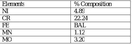
The material such as AISI 2205 is used in the experiments. Duplex stainless steels (DSSs) have a heterogeneous microstructure mainly composed of austenite (face-centred-cubic,γ-phase) and ferrite (body-centred-cubic, α-phase). The concentration of these major phases is controlled by chemical composition and thermal history during manufacturing. Basically DSSs are classified into five groups: lean DSS (UNS S32101, UNS S32304), Mo-containing lean DSS (UNS S32003), standard DSS (UNS S31803,
UNS S32205), super DSS (UNS S32507) and hyper DSS (UNS S32707, UNS S33207).
DSS 2205 has been used to fabricate oil and gas transport pipelines, flow lines, separators, scrubbers, pumps, manifolds, downhole production tubing and well casing.
Elements % Composition
NI 4.89
CR 22.24
FE BAL
MN 1.12
MO 3.20
Table-1 DSS2205 chemical composition
Table 1 shows the chemical properties of DSS 2205 as per the tested report.
III.EXPERIMENTALPROCEDURE
ISSN(Online): 2319-8753 ISSN (Print) : 2347-6710
I
nternational
J
ournal of
I
nnovative
R
esearch in
S
cience,
E
ngineering and
T
echnology
(A High Impact Factor, Monthly, Peer Reviewed Journal)
Visit: www.ijirset.com Vol. 8, Issue 3, March 2019
Fig: 1 Fibre Laser Cutting Machine
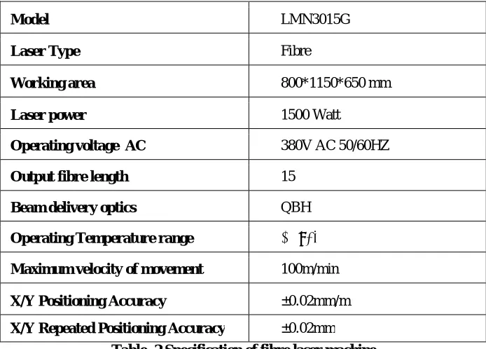
Figure 1 Shows the machine where experiments conducted. Specification of machine given in below table
Model LMN3015G
Laser Type Fibre
Working area 800*1150*650 mm
Laser power 1500 Watt
Operating voltage AC 380V AC 50/60HZ
Output fibre length 15
Beam delivery optics QBH
Operating Temperature range 10 ̴ 35
Maximum velocity of movement 100m/min
X/Y Positioning Accuracy ±0.02mm/m
X/Y Repeated Positioning Accuracy ±0.02mm
ISSN(Online): 2319-8753 ISSN (Print) : 2347-6710
I
nternational
J
ournal of
I
nnovative
R
esearch in
S
cience,
E
ngineering and
T
echnology
(A High Impact Factor, Monthly, Peer Reviewed Journal)
Visit: www.ijirset.com Vol. 8, Issue 3, March 2019
IV.PARAMETERS CONSIDERD FOR EXPERIMENT
4.1 Input Parameters
Most Effective Parameters for laser cutting are THICKNESS, CUTTING SPEED NOZZLE DAIMETER AND LASER POWER. Following table shows the factors and levels chosen for experiment.
FACTORS UNIT LEVEL 1 LEVEL 2 LEVEL 3
Thickness mm 1.5 3 5
Cutting Speed m/min 1 3 7
Nozzle Diameter mm 1.5 2.0 2.5
Laser power kw 1.1 1.3 1.5
Table-3 Input Parameters
4.2 Output Parameters
4.2.1 Kerf Width
Kerf width is defined as the width of material that is removed by a cutting process.
When a part is cut on laser, the objective is to produce accurate cut with final dimension as close as possible.
Fig-2 Kerf Width
4.2.2 Kerf Taper
The kerf taper angle is one of the most important quality characteristics because it is one of the measures for the geometrical accuracy of the machined cavities. Due to Gaussian beam distribution of the laser, the kerf taper is the inherent cut characteristics obtained on the machined surfaces. It is measuring through following equation.
where,
Kwt is top kerf-width, Kwb is bottom kerf-width t is sheet thickness.
(deg) = −
ISSN(Online): 2319-8753 ISSN (Print) : 2347-6710
I
nternational
J
ournal of
I
nnovative
R
esearch in
S
cience,
E
ngineering and
T
echnology
(A High Impact Factor, Monthly, Peer Reviewed Journal)
Visit: www.ijirset.com Vol. 8, Issue 3, March 2019
Fig-3 Kerf Taper
V. EXPERIMENTAL TABLE
Following are the Experimental runand results.
INPUT PARAMETERS OUTPUT PARAMETERS
Sr no. Thickness
(mm)
Nozzle Diameter (mm)
Cutting Speed (m/min)
Laser power (kw)
Kerf Width (mm) Kerf Taper (degree)
Straight Circular Straight Circular
1 1.5 1.5 7 1.3 0.26 0.16 2.121 2.981
2 1.5 1.5 7 1.5 0.28 0.28 2.140 2.981
3 1.5 1.5 7 1.1 0.19 0.15 2.694 2.312
4 1.5 2 7 1.3 0.14 0.20 3.096 1.705
5 1.5 2 7 1.5 0.16 0.29 2.713 2.150
6 1.5 2 7 1.1 0.10 0.12 2.045 3.024
7 1.5 2.5 7 1.3 0.15 0.13 1.548 1.697
8 1.5 2.5 7 1.5 0.15 0.29 2.790 1.697
9 1.5 2.5 7 1.1 0.14 0.11 2.771 2.752
10 3 1.5 3 1.3 0.23 0.91 1.720 4.739
11 3 1.5 3 1.5 0.30 0.69 1.213 4.414
12 3 1.5 3 1.1 0.05 0.79 1.596 1.968
13 3 2 3 1.3 0.22 1.16 2.255 3.669
14 3 2 3 1.5 0.27 0.52 0.860 1.849
15 3 2 3 1.1 0.00 0.00 0.000 0.000
16 3 2.5 3 1.3 0.31 0.31 0.516 1.158
17 3 2.5 3 1.5 0.34 0.39 0.182 0.355
18 3 2.5 3 1.1 0.09 0.00 1.854 0.000
19 5 1.5 1 1.3 0.28 0.23 3.302 8.790
20 5 1.5 1 1.5 0.59 0.41 0.092 1.108
21 5 1.5 1 1.1 0.00 0.48 0.000 0.554
22 5 2 1 1.3 0.44 0.54 0.785 1.361
23 5 2 1 1.5 0.49 0.39 0.791 2.508
24 5 2 1 1.1 0.00 0.51 0.000 0.315
ISSN(Online): 2319-8753 ISSN (Print) : 2347-6710
I
nternational
J
ournal of
I
nnovative
R
esearch in
S
cience,
E
ngineering and
T
echnology
(A High Impact Factor, Monthly, Peer Reviewed Journal)
Visit: www.ijirset.com Vol. 8, Issue 3, March 2019
VI.RESULTS AND DISCUSSION
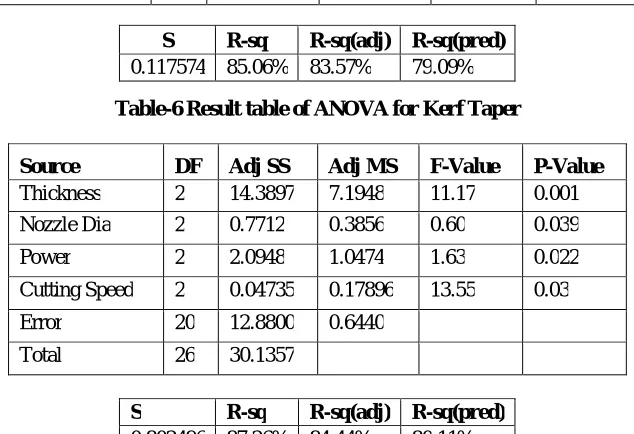
As per ANOVA Analysis we can find the percentage contribution of input parameters for Kerf width as shown in below Table.
Table-5 Result table of ANOVA for Kerf Width
Source DF Adj SS Adj MS F-Value P-Value
Thickness 2 0.313522 0.156761 11.34 0.001
Nozzle Dia 2 0.001172 0.000586 0.04 0.042
Power 2 0.023993 0.011996 0.87 0.035
Cutting Speed 2 0.03135 0.15676 12.47 0.00
Error 20 0.276475 0.013824
Total 26 0.615161
Table-6 Result table of ANOVA for Kerf Taper
Source DF Adj SS Adj MS F-Value P-Value
Thickness 2 14.3897 7.1948 11.17 0.001
Nozzle Dia 2 0.7712 0.3856 0.60 0.039
Power 2 2.0948 1.0474 1.63 0.022
Cutting Speed 2 0.04735 0.17896 13.55 0.03
Error 20 12.8800 0.6440
Total 26 30.1357
S R-sq R-sq(adj) R-sq(pred)
0.802496 87.26% 84.44% 80.11%
Minimum kerf width generates for Straight Profile at lower power of 1.1kw with is 0.05mm
Minimum Kerf Taper generates at Straight Profile Maximum power of 1.5 kw is 0.09o
Minimum kerf width generates for Curved Profile at lower power of 1.1kw with is 0.11mm
Minimum Kerf Taper generates at Curved Profile Maximum power of 1.5 kw is 0.32o
Regression Equation
Kerf Taper = 0.78 + 0.398 Thickness - 1.752 Nozzle Dia + 2.19 Power + 0.237 Cutting Speed
Kerf Width = -0.672 + 0.1658 Thickness - 0.0148 Nozzle Dia + 0.180 Power + 0.0570 Cutting Speed
S R-sq R-sq(adj) R-sq(pred)
ISSN(Online): 2319-8753 ISSN (Print) : 2347-6710
I
nternational
J
ournal of
I
nnovative
R
esearch in
S
cience,
E
ngineering and
T
echnology
(A High Impact Factor, Monthly, Peer Reviewed Journal)
Visit: www.ijirset.com Vol. 8, Issue 3, March 2019
REFERENCES
1. Avanish Kumar Dubey,VinodYadava “Laser beam machining review paper”,International Journal of Machine Tools & Manufacture Vol 48, pp.609–628, 2008.
2. Avanish Kumar Dubey, Vinod Yadava “Multi-objective optimization of laser beam cutting process” Optics & Laser Technology Vol 40, pp 562– 570, 2008
3. Dhrupal J. Kotadiya, Jaydeep M. Kapopara, Anjal R. Patel, Chirag G. Dalwadi D. H. Pandya “Parametric analysis of process parameter for Laser cutting process on SS-304” Materials Today: Proceedings Vol 5, pp.5384–5390,2018
4. S. Stelzer, A.Mahrlea, A. Wetziga, E. Beyera, “Experimental investigations on fusion cutting stainless steel with fiber and CO2 laser beams” Physics Procedia Vol 41,pp.399–404, 013
5. J A. Lamikiz, L.N. Lo´pez de Lacalle, J.A. Sa´nchez, D. del Pozo, J.M. Etayo, J.M. Lo´peza “CO2 laser cutting of advanced high strength steels (AHSS) ” Applied Surface Science Vol 242,pp.362–368, 2005
6. CihanKaratas , Omer Keles , Ibrahim Uslan Yusuf Usta “Laser cutting of steel sheets: Influence of workpiece thickness and beam waist position on kerf size and stria formation” Journal of Materials Processing Technology Vol 172, pp.22–29, 2005
7. Shang-Liang Chen * “The effects of high-pressure assistant-gas flow on high-power CO2 laser cutting” Journal of Materials Processing Technology Vol 88,pp.57–66,1999
8. Chen-Hao Li, Ming-Jong Tsai, Ciann-Dong Yang “Study of optimal laser parameters for cutting QFN packages by Taguchi’s matrix method” Optics & Laser Technology Vol 39, pp.786–795, 2007
9. Ulas- C- aydas, Ahmet Hasc- alık “Use of the grey relational analysis to determine optimum laser cutting parameters with multi-performance characteristics” Optics & Laser Technology Vol 40,pp.987–994, 2008
10. Bekir Sami Yilbas, MianMobeenShaukat, Farhan Ashraf “Laser cutting of various materials: Kerf width size analysis and life cycle assessment of cutting process” Optics and Laser Technology Vol 93, pp.67–73,2017
11. Dong-Gyu AHN, Kyung-Won BYUN “Influence of cutting parameters on surface characteristics of cut section in cutting of Inconel 718 sheet using CW Nd:YAG laser” Trans nonferrous Met. Soc China Vol 19, pp.32-39, 2009
12. D. J. Kotadiya, D. H. Pandya “Parametric analysis of laser machining with response surface method on SS-304” Procedia Technology Vol 23, pp.376–382, 2016